1
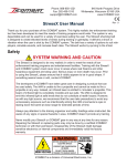
PLEASE NOTE:
This installation guide is not a substitute for the
“Installation and Owner’s Manual” that will be furnished
with the Guardian® Home Standby Generator or the
“Owner’s Manual” furnished with the Guardian® Ultra
Source Portable Generator you may purchase in the
future. Please review the installation procedure again at
the time of generator installation. This kit is not intended
for use with the Guardian® Liquid-Cooled Generator
product line. This kit is not suggested to be compatible
with other generator manufacturer’s products.
GENERAC POWER SYSTEMS, INC.
P.O. BOX 297 • WHITEWATER, WI 53190
www.generac.com
Part#D5507
Install your Ready Kit at the construction
stage or to pre-existing homes . . .
Use your
Portable Generator for
emergency power now . . .
. . . Later install your
Standby
for automatic emergency power!
KIT INCLUDES
5FT. POWER CORD
with NEMA 14-50 plug for
Guardian Portable Gensets
• 100 AMP automatic
transfer switch with built-in load center
• 30ft. and 2ft. pre-wired conduits
• 5ft. power cord and 50 AMP plug
Installation Guide
INSTALLATION DRAWING
AUTOMATIC TRANSFER SWITCH CONNECTED TO THE EXTERNAL CONNECTION BOX
PLEASE NOTE:
This installation guide is not a substitute for the “Installation and Owner’s Manual” that will be furnished
with the Guardian® Home Standby Generator or the “Owner’s Manual” furnished wit the Guardian® Ultra
Source Portable Generator you may purchase in the future. Please review the installation procedure again
at the time of generator installation. This kit is not intended for use with the Guardian® Liquid-Cooled
product line. This kit is not suggested to be compatible with other generator manufacturer’s products.
INTRODUCTION
Thank you for purchasing this “Generator Ready” Kit for
the GUARDIAN® air-cooled 12kW and 15kW automatic
generators. This kit will provide you the ability to pre-wire
your home or business in anticipation of the eventual
purchase of a GUARDIAN® home standby generator. This
kit will also enable the operation of the GUARDIAN®
ULTRA SOURCE portable generator for use with your
home. The majority of the labor involved in the generator
installation is in the wiring. If you are purchasing for new
construction or retro-fitting in an existing home this kit
will save you time and money in process. When the time
comes to add your GUARDIAN® Automatic Home Standby
Generator, all you have left is to connect the unit to the fuel
source and install a wiring harness from the generator to
the external connection box. Then, just add your starting
battery and you have the ultimate automatic home standby
generator system. The Guardian® is on duty.
Four commonly used safety symbols accompany the
DANGER, WARNING and CAUTION blocks. The type of
information each indicates follows:
This symbol points out important safety
information that, if not followed, could endanger
personal safety and/or property of you and others.
This symbol points out potential explosion hazard.
This symbol points out potential fire hazard.
This symbol points out potential electrical shock
Generac cannot possibly anticipate every possible
circumstance that might involve a hazard. The warnings in
this manual, and on tags and decals affixed to the unit are
therefore, not all-inclusive. If you use a procedure, work
method or operating technique Generac does not
specifically recommend, you must satisfy yourself that it
is safe for you and others. You also must make sure the
procedure, work method or operating technique that you
choose does not render the equipment unsafe.
ELECTRICAL HAZARDS • Utility power delivers extremely high and dangerous
voltages to the transfer switch as does the standby
generator when it is in operation.
• Do not handle any kind of electrical device while
standing in water, while barefoot, or while hands or feet
are wet. DANGEROUS ELECTRICAL SHOCK MAY
RESULT.
• In case of accident caused by electric shock,
immediately shut down the source of electrical power. If
this is not possible, attempt to free the victim from the
live conductor. AVOID DIRECT CONTACT WITH THE
VICTIM. Use a non-conducting implement, such as a
rope or board, to free the victim from the live
conductor. If the victim is unconscious, apply first aid
and get immediate medical help.
• Never wear jewelry when working on this equipment.
Jewelry can conduct electricity resulting in electric
shock, or may get caught in moving components
causing injury.
hazard.
SAVE THESE INSTRUCTIONS – The manufacturer
suggests that these rules for safe operation be
copied and posted near the unit’s installation site.
Safety should be stressed to all operators and
potential operators of this equipment.
1
Installation Guide
Designed with the
homeowner in mind!
2
KIT INCLUDES:
3
50 AMP PLUG ON 5FT. POWER CORD
1
THE EXTERNAL CONNECTION BOX
Located outside the home nearest the incoming gas
service.
4
30’ FLEXIBLE CONDUIT
Pre-wired from the automatic transfer switch with builtin emergency load center for connection to the external
connection box.
PRE-WIRED AUTOMATIC TRANSFER SWITCH* AND
EMERGENCY LOAD CENTER WITH 12 CIRCUITS
Installed within 1 foot of the home’s main distribution
panel. This transfer switch will provide smooth and safe
transition between utility and generator power.
Eliminates the need to run extension cords.*When used
with a portable generator the transfer from utility to
generator power will have to be performed manually.
(See page 7)
2’ PRE-WIRED CONDUIT FOR EASY CONNECTION TO
THE HOME’S MAIN DISTRIBUTION PANEL
12 UL LISTED WIRE NUTS (not shown)
TOOLS REQUIRED:
Drill, drill bits, hole saw (type and length will be
determined by the materials you will be drilling and
cutting), open-end wrenches or adjustable wrenches,
socket wrenches or nut drivers, standard and Phillips
screwdrivers, sledge hammer, channel-lock pliers,
spade shovel, and safety goggles.
5
6
ITEMS YOU MUST PURCHASE:
70 AMP double pole circuit
breaker (must be the same
type as in your main electrical
distribution panel)
Ground rod with grounding
strap
Crushed stone or pea gravel
(approximately 10-12 cubic
feet)*
Black poly-film or other
vegetation blocking fabric*
Silicone caulk
Fasteners (to mount
connection box and automatic
transfer switch)
Power cord clamp (to secure
cord at the external connection
box
*Only required when a Guardian Home Standby
generator is be installed.
2
MANUAL TRANSFER OPERATION USING GUARDIAN® PORTABLE GENERATOR
TRANSFER TO GENERATOR POWER SOURCE WHEN
UTILITY POWER FAILS
1. Set the generator’s 50 amp circuit breaker to its OFF
(or open) position.
2. Turn OFF the utility power supply to the transfer
switch using the means provided (such as a utility
main line circuit breaker or supplementary 70 amp
circuit breaker installed in main panel.
Do not attempt to activate the transfer switch manually
until all power voltage supplies to the switch have been
positively turned off. Failure to turn off all power voltage
supplies may result in extremely hazardous and
possibly fatal electrical shock.
3. Remove 4 hex bolts holding on transfer switch cover.
Remove cover.
4. Use the manual transfer handle inside the transfer
switch (attached to sidewall with wingnut) to move the
main contacts to their “Standby” position, i.e., loads
connected to the standby power source (Figure 1).
Replace handle on side of box. Re-install transfer
switch cover.
5. Insert the NEMA 14-50 plug (from the power cord that
you have installed) into the mating receptacle on the
generator control panel.
6. Start the generator.
7. Let the engine stabilize and warm up for a few minutes.
8. Set the generator’s 50 amp circuit breaker to its’ ON
(or closed) position.
Figure 1 - Manual Transfer Switch Operation
Choose a lamp or light fixture located in a frequently
occupied area of the house as a signal light to tell
you when utility power has returned. This light
should be on a utility powered circuit only so it
operates independent of the generator.
TRANSFER BACK TO UTILITY POWER SOURCE
When utility power has been restored, you will want to
transfer back to that source and shut down the generator.
This can be accomplished as follows:
1. Set the generator’s 50 amp circuit breaker to its OFF
(or open) position.
2. Let the engine run for a minute or two at no-load to
stabilize the internal temperatures.
3. Turn off the generator.
4. Turn OFF the utility power supply to the transfer
switch using the means provided (such as a utility
main line circuit breaker or the supplementary 70 amp
circuit breaker that was installed in the main panel).
Do not attempt to activate the transfer switch manually
until all power voltage supplies to the switch have
positively turned off. Failure to turn off all power voltage
supplies may result in extremely hazardous and
possibly fatal electrical shock.
5. Remove transfer switch cover.
6. Use manual transfer handle to move the main
contacts to their “utility” position, i.e., load connected
to the utility power source (Figure 1). Replace handle
on inside of transfer switch box. Replace transfer
switch cover.
7. Turn ON the utility power supply to the transfer switch
using the means provided (such as the utility main line
circuit breaker or the supplementary 70 amp circuit
breaker installed in the main panel.
8. Remove the NEMA 14-50 plug from the mating
receptacle on the generator control panel.
9. Turn ON the utility power supply to the transfer switch
using the means provided (such as utility main line
circuit breaker) or supplementary 70 amp circuit
breaker you have installed in the main panel.
After utilizing the 5 ft. electrical power cord for operation with
the GUARDIAN® ULTRA SOURCE portable generator you
must remove it. Open the external connection box. Remove
the fasteners holding the Black, Red, White, and Green wires
in place. Remove wires from threaded lugs and from under
ground screw. Replace fasteners and ground screw. Loosen
the cable clamp and slide the power cord out of the external
connection box. Store the power cord with your GUARDIAN®
ULTRA SOURCE portable generator.
7
Installation Guide
11.
Feed Conduit and Wires
8
Silicone
Caulk
The outer diameter of the
conduit connector is 1-11/16”
8.
From the inside of the house, feed the end of the 30foot conduit (INCLUDED and pre-wired from transfer
switch) through the wall to outside.
Using appropriate
fasteners,
mount
external connection
box over pre-drilled
hole to fully conceal
the hole. (Seal around
the hole and conduit
with silicone caulk
from both outside
and inside of house.)
11 Mount External Connection Box
--- WARNING --The external connection box must be locked to ensure
safety and to discourage tampering.
12 Mounting Automatic Transfer Switch
Threaded Lock Nut
9
The outer diameter
of the threaded end
is 15/16 inches.
1ft.
9.
Remove the threaded lock nut from the conduit coupling.
1010
Connect Wires
Connect
Wires
Knockout
4
10. Remove the knock out
in the lower right corner of
the external connection box.
From the rear of the
connection box, feed wires
& 4 pin plug into box. Slip
the lock nut over wires and
plug and tighten securely
onto conduit coupling.
Connect the black, red, and
white wires to separate
threaded lugs and tighten
securely. Screw the green
ground wire securely to the
bottom of the box. NOTE:
THE 4-PIN PLUG WILL not
be connected to any
mating plug or other wires.
12. Locate automatic transfer switch with built-in
emergency load center within one foot of main
distribution panel. The automatic transfer switch can
be located to the left or right of main distribution
panel. Hold transfer switch against the mounting
surface. Level the transfer switch and mark the
mounting holes. Drill the appropriate size pilot holes.
Mount the automatic transfer switch to mounting
surface with appropriate fasteners.
DANGER: Although you may choose to perform
electrical connections yourself, Generac Power Systems,
Inc. recommends that a licensed electrician or individual
with complete knowledge of electricity perform the
procedures in sections 13 and 14.
DANGER: Switch service main circuit
breaker to “off” or open position prior to
removal of cover or removal of any wiring of
the main electrical distribution panel. The “OFF”
wires connected to the service main circuit
breaker remain live or “hot”. Avoid contact with these
wires and the service main circuit breaker connection lugs.
NOTE: Balance must be maintained when moving circuit
locations from main electrical distribution panel to
emergency load center. Circuit breaker positions
alternate buss bars vertically. Circuits sharing a neutral
wire should either be moved together to adjacent
positions in emergency load center or not moved. If you
are unsure of proper procedure or if your installation
differs from that described in this guide, consult a
licensed professional at this time.
13a Connection of Emergency Circuits
13b. In your main panel, remove the black (hot) wire from
a circuit breaker that protects a circuit you want to
have powered in the event of a power failure. Wire
nut the black wire to the matching circuit lead wire
from the emergency circuit breaker from load center
in the transfer switch. (All circuit wires are color
coded and labeled for easy identification). Repeat
this process with remaining circuits to be powered
by the generator. White wires (neutral) in your main
distribution panel should remain connected to
neutral bar. It is not necessary to move them. The
emergency load center in the transfer switch supplies
the following circuits: (5) 15A/120V, (3) 20A/120V,
(1) 20A/240V and (1) 30A/240V.
14
13a. Remove the main electrical distribution panel cover.
Remove appropriate size knockout from the bottom
or side of the main panel. (A 2-foot flexible conduit is
pre-wired from the transfer switch with built-in load
center.) Remove threaded lock nut from conduit
coupling. Feed all wires through knockout into main
panel. Slip lock nut over wires and tighten securely
onto conduit coupling.
13b Connection of Emergency Circuits
Install 70 AMP Circuit Breaker
14. Install the 70 Amp double pole circuit breaker that
you have purchased into main electrical distribution
panel. This circuit breaker must be compatible with
your main electrical distribution panel. It may be
necessary to reposition remaining circuit breakers or
remove circuit breakers that have been disconnected
to accommodate the insertion of the 70 Amp double
pole circuit breaker. Connect white wire to the main
distribution panel neutral bar. Connect solid green
wire to main electrical panel ground bar. Connect the
black and red wires to the 70 Amp double pole circuit
breaker.
UL approved wire nuts are included with installation kit.
®
NOTE: Circuits to be moved must be protected by same
size breaker. For example, a 15 amp 120V circuit in
emergency load center will replace a 15 amp 120V
circuit in main panel.
YOUR GUARDIAN
GENERATOR READY KIT
IS NOW INSTALLED!
5
Installation Guide
OPTIONAL USE WITH A PORTABLE GENERATOR
An added feature of the GENERAC® Generator Ready Kit is the ability to hook up a
GUARDIAN® ULTRA SOURCE portable generator. Included in the kit is a 5 foot
electrical power cord (black & red), neutral (white) and ground (green) wires. At
one end are the terminal connectors. At the other end is the male connector (NEMA
14-50) which plugs into the GUARDIAN® ULTRA SOURCE portable generator’s
control panel. To install this option, insert the terminal wire end of the power cord
into the bottom of the external connection box through the conduit clamp (not
included) from the outside. Allow about an inch of the power cord insulation to
enter beyond the clamp to the inside of the box. TIghten clamp securely. Attach
ground wire (green) to the bottom of the box using the supplied ground screw and
pre-drilled hole. Connect red, black and white wires each to separate lug posts.
Make sure hold down nuts are tightened securely.
CAUTION:
If you are performing
this step after the 30 foot
conduit
has
been
connected inside of the
external connection box
you must match the
black, red and white
wires to the lugs of the
wires previously placed.
(For example: black to
black; red to red, etc.)
50 AMP POWER PLUG
ULTRA SOURCE PORTABLE GENERATOR CONTROL PANEL
NEMA 14-50
Receptacle
EXTERNAL
CONNECTION BOX
5 FOOT POWER CORD
WITH PLUG
Lug Posts
Bring power
cord through
here
NEMA
14-50 Plug
6
Ground
Screw
Site Preparation and Standby Generator Placement
1
2
5
3 ft.
3
Crushed Stone or Pea Gravel
1.
4
PLAN THE LOCATION OF YOUR GENERATOR.
the location. Drill a 1-3/4” diameter hole through the
sheathing and siding with hole saw.
NOTE: Do not place the generator directly under a
window.
6
Select an area outside of your home nearest your
incoming gas service. Determine where the
generator will be placed outside of the home.
Arrange for fuel piping with shut-off valve to be run
to this location. Keep in mind that GENERAC®
recommends placement no closer than 3 feet to any
structure. Local codes may dictate placement
farther from a structure. The 3/4” fuel inlet is located
6 inches in from the rear of the unit on the right side
if facing the unit from the front. The fuel inlet is 10.2
inches above ground.
2.
Clear an area 5-1/2 feet by 5 feet of grass and
vegetation to a depth of 5 inches. This includes the
distance the generator should be set away from a
structure (3 feet) and 6 inches beyond the width and
length of the generator mounting pad (48" L x 24" W).
3.
Lay black poly-film to cover the area.
4.
Fill the area to ground level with pea gravel or
crushed stone.
5.
Drive an 8-foot grounding rod into the ground to
grade. Make sure grounding rod and strap are not
exposed above ground level. (NEC code applies to
grounding method.)
6.
Drill Hole Through House
1-3/4”
Diameter Hole
7.
While adhering to all local electrical codes, route the
30 foot conduit along ceiling/floor joists and wall
studs to the location where the conduit will pass
through the wall to the exterior of the house.
7
Drill Pass Through Hole
1-3/4”
Diameter Hole
Determine where the flexible conduit will pass
through the house from inside to outside. When you
are certain you have clearance on each side of the
wall, drill a small pilot hole through the wall to mark
3