Download Automatic Control Panel, Type EP103
Transcript
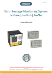
Automatic Control Panel, Type EP103
For electrically operated gates, barriers & doors
User Manual
Version 3.12
Edition 1 L
DAAB
Box 125,
S-284 22 Perstorp
Sweden
Phone: +46 (0)435 77 95 00
Fax: +46 (0)435 77 95 29
E-mail: [email protected]
www.daab.nu
DAAB UK
Unit D5
Chaucer Business Park
Kemsing Kent TN15 6YU
England
Phone: +44 (0)1732 765476
Fax: +44 (0)1732 765478
E-mail: [email protected]
Contents
Declaration of conformity ..................................................................................................................... 3
Safety instructions ................................................................................................................................ 4
Recycling of used electronics.............................................................................................................. 4
‘Stop’ signals and automatic closing .................................................................................................. 5
Technical specification ......................................................................................................................... 6
Mounting................................................................................................................................................. 7
Connection instructions ....................................................................................................................... 8
Display Diodes..................................................................................................................................... 13
Channel list for EP103......................................................................................................................... 15
Channel list for vehicle detector........................................................................................................ 21
Service fault finding ............................................................................................................................ 24
Error messages ................................................................................................................................... 25
Descriptions and pictures in this user manual is not binding. DAAB reserves the right to whenever
make product changes. These changes can be done without updating this user manual.
2
Notes
FC
Stands for “fotocell” - Photocell
KSS
Stands for “klämskydd stängning” - Safety buffer, close direction
KSÖ
Stands for “klämskydd öppning” - Safety buffer, open direction
S
(in GS2 etc.) stands for “stänga” - Close
SL
Stands for “slinga” – Inductive ground loop
Ö
(in GÖ2 etc.) stands for “öppna” - Open
Ö/S
Stands for “Öppna/Stäng” - Open/Close
User manual EP103
Version 3.12 edition 1 L
Declaration of conformity
According to AFS 1994:8, Attachment 2 A,
Manufacturer:
DAAB Portteknik AB
Box 125
284 22 Perstorp
Sweden
Phone: +46 (0)435 77 95 00
Fax: +46 (0)435 77 95 29
Declares that:
Product:
Automatic Control Panel, Type EP103-1, EP103-2
for electrically operated gates / barriers and doors, is manufactured in accordance
with:
Low voltage directive (LVD) 73/23/EEC
The directive for electromagnetic compatibility (EMC) 89/3366/EEC with changes
92/31/EEC and 93/68/EEC.
Is produced in agreement with following harmonised standards:
SS-EN 418
"Safety of machinery - Emergency stop equipment, functional aspects Principles for design"
SS-EN 50081-1
"Electro-magnetic compatibility - Generic emission standard - Part 1:
Residential commercial and light industry"
SS-EN 55014-1
"Electro-magnetic compatibility - Requirements for household appliances,
electric tools and similar apparatus - Part 1: Emission"
SS-EN 55022
"Information technology equipment - Radio disturbance characteristics - Limit
and methods of measurement"
SS-EN 60204-1
"Safety of machinery - Electrical equipment of machines - Part 1: General
Requirements"
SS-EN 61000-3-2
"Electro-magnetic compatibility (EMC) - Part 3-2: Limits - Limit for harmonic
current emissions (equipment input current up to and including 16 A per
phase)"
SS-EN 61000-3-3
"Electro-magnetic compatibility (EMC) - Part 3: Limits - Section 3: Limitation
of voltage fluctuations and flicker in low-voltage supply systems for equipment
with rated current up to and including 16A"
SS-EN 61000-4-2 A 2 "Electro-magnetic compatibility (EMC) - Part 4-2: Testing and measurement
techniques - Electrostatic discharge immunity test"
SS-EN 61000-4-3
"Electro-magnetic compatibility (EMC) - Part 4: Testing and measurement Section 3: Radiated, radio-frequency, electromagnetic field immunity test"
SS-EN 61000-4-4
"Electro-magnetic compatibility (EMC) - Part 4: Testing and measurement
techniques - Section 4: Electrical fast transient/burst immunity test - Basic EMC
Publication"
SS-EN 61000-4-6
"Electro-magnetic compatibility (EMC) - Part 4: Testing and measurement Section 6: Immunity to conducted disturbances, induced by radio-frequency
fields"
SS-EN 61000-4-11 "Electro-magnetic compatibility (EMC) - Part 4: Testing and measurement
techniques - Section 11: Voltage dips, short interruptions and voltage variations
immunity tests"
SS-EN 61000-6-2
"Electro-magnetic compatibility (EMC) - Part 6-2: Generic standards - Immunity
for industrial environments"
User manual EP103
Version 3.12 edition 1 L
3
Safety instructions
The manual that’s delivered with the control panel should be read through carefully, it contains
important information about safety, commissioning and usage. Risk for serious personal injury or
material damage can arise if the safety instructions aren’t followed.
WARNING! Incorrect installation or wrong usage of this product can cause injury
to persons, animals or property.
•
•
•
•
•
•
•
•
•
•
•
•
•
•
•
•
•
•
•
Connection / inspection should only be carried out by a suitably qualified person.
The gate / barrier / door can be dangerous if incorrectly connected / programmed with the control
panel.
The control panel contains live components when connected to a power supply.
Disconnect power supply / battery backup before any work is carried out on the unit.
Check that the earth lead is correctly connected: all of the metal parts in the gate / barrier
construction, and all system components with an earth terminal should be connected to protective
earth.
The isolator switch must be switched off for the personal safety whilst working on the unit.
When handling the unit, ESD-directions should be followed.
The unit should be mounted inside a cabinet designed for its surroundings. The cabinet should
protect the electronics from damp, dust and risk of contact. If the cabinet is placed outside, or is at
risk of condensation, a suitable heating element must be employed.
The electronics should be protected against damp.
Packing material should be handled and sorted according to valid EU directives. Keep plastic bags
etc. out of the reach of children.
Store this manual in a suitable location for future reference.
The unit is designed solely for the application that is given in this manual. Any operation not
expressly specified could damage the unit and cause potentially hazardous gate operation.
DAAB Portteknik declines all responsibility for consequences arising from the misuse of this
product or usage that deviates from its design.
Mount all safety components (photoelectric sensors, safety buffers, etc.) in accordance with
specific manuals and technical standards.
The unit or associated components must not be modified in any way.
The end user should only carry out repairs to this equipment if they are suitably qualified.
The installer must inform the end user of the control panel’s functions and how the gate / barrier /
door can be released (open manually) during power failure or other emergency situation.
People, animals and property should be kept clear of the gate / barrier / door at all times.
Radio transmitters and other remote controls should be kept out of reach of children to avoid
unintentional operation of the gate / barrier / door.
Recycling of used electronics
DAAB Portteknik will accept old DAAB circuit cards for environment friendly recycling.
4
User manual EP103
Version 3.12 edition 1 L
‘Stop’ signals and automatic closing
Stop signals
Unless a ‘Stop’ button is mechanically latched to keep the control circuit broken, the gate / barrier /
door will close if it receives another command signal (open or close) and a time has been set in
Channel C52. This applies to any stop signal and also the ‘stop’ function available via the
programmable inputs (Open/Stop/Close) in channels C61 and C62.
WARNING! Any ‘command’ signal will start the automatic close countdown after a
stop signal has been sent. This applies to all normal open and close signals as well
as remote inputs such as induction loops, time switches, GSM modules etc.
For example: If a vehicle drives on and off a “free exit loop” whilst the gate / barrier / door has been
held open by a ‘stop’ signal, the control panel will begin the automatic countdown and the equipment
will close in the time set in either channel C49 or C50..
Read more about automatic closure in the chapters for respective types of equipment.
C52
Setting automatic closure after ‘stop’ has been effected.
0
No automatic closing signal is given by the panel after a ‘stop’ signal is received.
Another command is required.
0,20-9,59
(min,sec)
No automatic closing signal is given by the panel until the set time has expired or
another command is received.
Hold open
To hold equipment open whilst working in the vicinity either:
• Open with an instruction and isolate from the mains power supply.
• Open with a continuous signal.
• Open with a signal and use a lock-down stop button.
User manual EP103
Version 3.12 edition 1 L
5
Technical specification
Dimensions (WxHxD)
Weight
190x224x60 mm.
Model type Ep103-2 =1.7 kg. Model type EP103-1=1.4 kg.
Supply voltage
Supply voltage, three phase
Supply voltage, single phase
Frequency
EP103 is suitable for three-phase or single-phase operation.
3x400VAC, 3x230VAC, (±10%) Fuse max T10A.
1x230VAC (±10%) Fuse max T10A.
50Hz.
Motor
Motor, three-phase 3x400V
Motor, three-phase 3x230
Motor, single-phase
EP103-1 for single drive motor, EP103-2 for two drive motors.
three-phase induction motor, 0.18-0.75kW.
three-phase induction motor, 0.18-0.37kW.
single-phase motor with operating condenser 0.18-0.25kW.
Fuses
External fuse required = 10A.
Power consumption
Automatic controls max 22 VA + electric motors.
Temperature range
0 to 50°C.
EMC
Emission: EN 61000-6-3:2001 EN 55022 class B, EN 55014-1, EN 61000-3-2, EN61000-3-3.
Immunity: EN 61000-6-2:1999 EN 61000-4-2, EN 61000-4-3, EN 61000-4-4, EN 61000-4-5,
EN 61000-4-6, EN 61000-4-8, EN 61000-4-11.
6
LVD
EN 60204-1.
Safety Buffers
Closing direction
Opening direction
Sensitivity
Resistance
There are 3 analogue inputs for safety buffer monitoring.
2 inputs, KSS1 and KSS2, for safety buffers - close.
There is one KSÖ input for safety buffers - open.
There must be >25% differentials when a buffer is actuated.
1,0-8,2kΩ with 1% tolerance and power resistance at least ½W.
Safety circuit
Max resistance
Cable length
Inputs
Max 3Ω in stop circuit.
Cable length: 0.75mm2 =max 60m. 1.5mm2 =max 120m.
1 analogue input 0-50V meters voltage after stop circuit.
Motor protection
Range of measurement
Internal motor protection circuit meters current on phase L1.
0.5-4 A
Load sensor
Range of measurement
Measures used power.
0.00-1.99 kW.
Digital inputs (9)
Logic 0
Logic 1
Input current
Cable length
For operation and control of gate.
0-8V
12-30V
5mA at 24V
Max 200m.
Supply to photocell
24V max 50mA.
24V DC output
Load
24V DC for supply to external access control or signal devices etc.
Max 300mA.
Communication
RS-485 between two EP103. Max. cable length 1000 meters.
Degree of protection
The circuit card is intended for mounting inside a cabinet.
User manual EP103
Version 3.12 edition 1 L
Mounting
To ensure that the panel is electrically safe and works correctly it is important that it is mounted inside
a weatherproof enclosure inside a secure area.
N.B. The circuit board is earthed via the earth rail, mounting rail, steel mounting panel and the
distance screws used for fastening.
• The control panel must be mounted on a metal panel.
• If the metal panel is painted, make sure that the paint is scraped away so a good electrical contact
is made.
• The four distance pieces supplied must be used to mount the control panel.
• The earth rail must be mounted on the metal panel.
189.2
163.8
30.4
12.7
Ø4.5(4x)
Screw M4
223.5
Control panel
188
Spacer
2pc washer
Mountingplate
plate
Mounting
withM4-thread
M4-winding
with
Earth terminal
User manual EP103
Version 3.12 edition 1 L
12.7
7
Connection instructions
Power Supply connection
For the EP103 control panel to be electrically safe, function correctly and comply with current
regulations, it is important that it is assembled and connected correctly.
NB: The circuit board must be earthed via the mounting plate.
1. The circuit board must be mounted on a metal plate.
2. If the plate has been painted, see that the paint is scraped off around the fixing points so that a
good contact is achieved.
3. The 4 No. M4x10 spacers included must be used..
4. An earth terminal strip must be available on the metal plate.
5. The earth terminal strip must be suitably connected to earth.
Remember!
• The power supply should only be connected by a competent person.
• The power supply to the circuit board should have a maximum T10A fuse.
• The power supply should be connected via a lockable isolator.
• Check that the supply and motor voltages are compatible.
• The largest motor size that can be connected is 0.75kW (3-phase 3x400V).
• See commissioning for how to check that the motor is running in the right direction.
Interchange V1 och
W1 and/or V2 och W2,
if motor is running in
wrong direction.
M
3~
T1
N
L1 L2 L3 U1 V1 W1 U2 V2 W2
Z1
U1 Z2
U2
Interchange V1 och
W1 and/or V2 och W2,
if motor is running in
wrong direction.
Interchange between
L2 and L3 if wrong
phase sequence.
Z1
U1 Z2
U2
Singel phase
motor
M
3~
N
Singel phase
motor
L1 L2 L3 U1 V1 W1 U2 V2 W2
1x230V+N
Säkras max T10A.
N
3-phase motor
D-connection
T1
3-phase motor
D-connection
M
3~
N
Supply singel phase 230V
Control panel
3x230V
Fuse max T10A.
M
3~
3-phase motor
Y-connection
L1 L2 L3 U1 V1 W1 U2 V2 W2
3-phase motor
Y-connection
N
3x400V+N
Fuse max T10A.
T1
Output 230V
max 1A
N
Control panel
Output 230V
max 1A
Control panel
Supply 3x230V without neutral
Output 230V
max 1A
Supply 3x400V with neutral
Interchange V1 och
W1 and/or V2 och W2,
if motor is running in
wrong direction.
3-phase motor
D-connection
U2
Z2
V2
U2
W2
V2
U2
W2
3-phase motor
Y-connection
Z1
Condenser
U1
W1
V1
U1
W1
V1
U1
Connection of electric motor
singel phase motor
Other voltages are available if requested.
8
User manual EP103
Version 3.12 edition 1 L
Input Connections
Remember!
• Connection should only be carried out by a competent person. It is important that any personal
electrostatic charge is discharged prior to working on the panel.
• The panel must be isolated from the power supply before commencing work.
• Remember that the gate may be dangerous if incorrectly commissioned.
• Do not connect anything in the safety circuit, e.g. relays or lamps, that may interfere with the
circuit. If an intermediate relay must be used to obtain open and closed signals, DAAB
should be contacted for instructions.
Safety buffers, stop and limit switches are considered part of the safety circuit.
• Safety buffer circuits must contain a 2.0KΩ or greater resistor to ensure that if the circuit fails, it
fails ’safe’.
• This control panel is designed for many applications, therefore not all the input signals may be
needed.
• Unused “Stop” terminals must be linked out and photocell / loop terminals to be linked if not used.
For explanation of the input signals see the next page.
Control panel
KSS1
KSS2
Safety circuit
KSÖ
Stop
Stop
Stop
GÖ1
GS1
GÖ2
GS2
Open
Close
Open
Close
Prog. input 1
Prog. input 2
+
Photocell/loop
OUT
-
Communication
Output 24VDC
max 300mA
Connection
terminals
User manual EP103
Version 3.12 edition 1 L
RS 485
+
-
1
2
3
4
5
6
7
8
9
10
11
12
13
14
15
16
17
18
19
20
21
22
23
24
25
26
27
28
29
30
31
32
33
34
35
36
24VDC
Safety
9
List of Input Signals
Safety buffer
Name
KSS1
KSS2
KSÖ
Term.
1,2
3,4
5,6
Function
Closing safety buffer, in action when closing. Resistance measurement.
Closing safety buffer, in action when closing. Resistance measurement.
Opening safety buffer, in action when opening. Resistance measurement.
Stop, safety circuit
Name
Safety Out
Stop
Stop
Stop
Term.
7
7,8
9,10
11,12
Function
Output for safety circuit 24V/0.5A
Stops gate. Contact normally closed, link required if not used.
Stops gate. Contact normally closed, link required if not used.
Stops gate. Contact normally closed, link required if not used.
Limit positions, safety circuit
Name
GÖ1
GS1
Term.
13
14
15
GÖ2
GS2
17
18
Function
Separate +24VDC for limit switches - motor 1
Opening limit switch for motor 1. Breaks contact in fully open position.
Closing limit switch for motor 1. Breaks contact in fully closed position.
Separate +24VDC for limit switches - motor 2
Opening limit switch for motor 2. Breaks contact in fully open position.
Closing limit switch for motor 2. Breaks contact in fully closed position.
Control keys
Name
+24VDC
Open
Close
+24V DC
Open
Close
+24V DC
Prog. Input 1
Prog Input 2
Term.
19
20
21
22
23
24
25
26
27
Function
24V DC output for access controls.
Open gate on open signal 24V DC.
Close gate on close signal 24V DC .
24V DC output for access controls.
Open gate on open signal 24V DC.
Close gate on close signal 24V DC.
24V DC output for access controls.
Programmable input.
Programmable input.
Photocell, safety loop
Name
+24V DC
FC/SL
0V
Term.
28
29
30
Function
Output for photocell/Induction loop 24V/50mA.
Photocell/loop, stops gate when closing. Contact normally closed, when powered.
Earth connection.
Communication
Name
RS485
Term.
31,32
Function
Communication with a separate DAAB panel.
24V DC output
Name
+24V DC
0V
Term.
33
34
Function
24V DC for supply to additional access controls
Earth termination.
Bridge connector
Name
Connection
10
Term.
35,36
Function
Connection terminal.
User manual EP103
Version 3.12 edition 1 L
Safety buffer connection
•
•
•
•
Resistors must always be placed in safety circuits on the buffer to enable the system to fail safe.
The resistance value must be 1,0-8,2kΩ, with 1% tolerance and power resistance at least ½W.
When connecting more than one buffer, use the same resistance value on all buffers.
Closing buffers mounted on the gate leaf powered by motor 1 should be connected to KSS1.
Closing buffers mounted on the gate leaf powered by motor 2 should be connected to KSS2.
There is a built-in safety buffer monitor on the board which functions with both mobile and static safety
buffers. The EP103 monitors itself by an auto-test, which takes place before each start and after every
stop. An error message is received if there is a fault. A 1,0-8,2kΩ resistor must be installed in the
safety buffer circuit. The principal of the safety system is that this resistance is measured and any
variation from this standard signals an alarm.
When mechanical switching type buffers are used, resistors must be connected in series with buffer. If
more than one DAAB type safety buffer is connected, these should be connected in series or parallel,
and the value of sum should be set in the control panel. If resistance switching buffers are connected
in series, use only one final resistor. See drawings below for details.
DAAB mechanical switching type safety buffer.
2,0k
red
black
Control panel
Solid state (resistance switching) safety buffer
parallel connection
Solid state (resistance switching) safety buffer
series connection.
Control panel
2,0k
Control panel
2,0k
2,0k
Connection between two DAAB EP 103 panels
To ensure correct communication between two DAAB panels it is important to take note of the
following:
• Choose a twisted two-core screened cable.
• Cable size should not be less 0,2mm2 .
• Choose a low capacitance cable with capacitance 50-70 μF/m.
• Check the polarity.
EP103
EP103
31 32
1
31 32
1
2
2
FKAR-PG 2x0,5
User manual EP103
Version 3.12 edition 1 L
11
Reading and Setting values
CXX
dXX
EXX
XXX
XXX-flash
+
↵
↵
Channel number for EP103
Channel umber for vehicle detector
Error message.
Read value
Write value.
Decrease channel or value
Increase channel or value.
Toggle between channel number and value
Save when entering value.
Description
All values are stored in accordance with a channel list, as with TV channels, where each TV channel
corresponds to a particular programme. Here, each channel corresponds to a certain control
parameter or a measured value. The display may either show a value of 1-3 digits, or a channel
number of two digits - a C or d will then be shown on the extreme left. This means Channel number.
Values may be both read and written; the value flashes when a setting is being changed.
If E (error) is displayed, followed by a number, this is an Error message. See error messages.
The ↵ key toggles between the value and the channel number. The value is saved in Write mode.
In channel mode, the + channel number key scrolls forward in the channel list. In Write, the value
increases.
In channel mode, the – channel number key scrolls backwards in the channel list. In Write, the value
decreases.
Save mode
If display keys are not pressed for 1.5 minutes, save mode is tripped and displays decrease in
brightness. As soon as a key is pressed, normal mode is resumed.
Read values
C01-C18 are read channels. By activating these you can only read the actual value.
Follow the procedure below in order to read values:
1. Press the ↵ key so that that display shows Channel number (C at extreme left).
2. Look at the channel list to check the number of the value you want to read.
3. Step up or down with the + or – key to the correct channel number.
4. Press the ↵ key; the Value appears on the display..
Write values
C30-C99 are write channels. By activating these you can set the actual value.
Follow the procedure below in order to write a value:
1. Press the ↵ key so that the display shows Channel number (C at extreme left).
2. Look at the channel list to check the number of the value you want to change.
3. Step up or down with the + or – key to the correct channel number.
4. Press the ↵ key; the Value appears on the display.
5. Press the + key. The value begins to flash.
6. Step up or down with the + or – key until the value you want to write is shown.
7. Press the ↵ key: the value is saved.
8. Press the ↵ key once again and you are out of the channel. CXX is shown
12
User manual EP103
Version 3.12 edition 1 L
Locked settings
Settings may be locked by service personnel, and cannot then be over written. In that case, channel
C99 will be set to 01. Contact service personnel if values need to be written or changed.
Error messages
If ‘E’ appears on the extreme left, this is an error message. When a key is pressed, this message
disappears and the display shows channel number.
Note all settings
Note all the settings written during commissioning in the channel list under value set (section on
channel list for EP103). It is best to use a pencil so that values can be changed.
Display Diodes
To make matters easier when commissioning and fault-finding, light diodes are provided to indicate
faults and input signals
Yellow light diodes loop detector
Lit diode means affected loop.
Fault message on display
When E (error) is shown on the display is it a
Fault message (see page 53).
Red light diodes for error indication
Unlit diode means no error.
Lit diode means error.
Flashing light diode means previous error,
diode goes off next time gate is operated
Green photocell diode normally on
Unlit means photocell/loop is actuated
Yellow light diodes for control keys
Lit diode means key actuated.
Yellow light diodes for limit position
Lit diode goes off when limit reached.
Green light diodes normally on
’Stopp’ diode goes out when stop is actuated
and stop circuit is broken.
User manual EP103
Version 3.12 edition 1 L
13
Red light diodes for alarm
Indication
Function
M1
Indicates that the load sensor has tripped out for motor 1.
M2
Indicates that the load sensor has tripped out for motor 2.
KSS1
Indicates an error on safety buffer circuit ‘closing 1’.
KSS2
Indicates an error on safety buffer circuit ‘closing 2’.
KSÖ
Indicates an error on safety buffer circuit ‘opening’
Normally
Off
Off
Off
Off
Off
Green light diodes normally on
Indication
Function
FC/SL
Indicates that photocell/loop circuit is live and unbroken.
24V DC
Indicates the presence of voltage.
STOPP
Indicates that stop circuit is live and unbroken.
Normally
On
On
On
Yellow light diodes indicating signals from limit positions
Indication
Function
GÖ1
Lit indicates that motor 1 can open more, off in open position
GS1
Lit indicates that motor 1 can close more, off in closed position
GÖ2
Lit indicates that motor 2 can open more, off in open position
GS2
Lit indicates that motor 2 can close more, off in closed position
Yellow light diodes indicating control signals
Indication
Function
PROG1
Indicates signal for programmable input 1
PROG2
Indicates signal for programmable input 2
STÄNG
Indicates signal for close.
ÖPPNA
Indicates signal for open.
14
User manual EP103
Version 3.12 edition 1 L
Channel list for EP103
The channel list is the same for control type EP103-1 (1 motor) and control type EP103-2 (2 motors).
Certain channels apply only to control type EP103-2. These are marked by an * before the channel
number.
Measured value to be read
No.
C00
C01
C02
C03
C04
C05
C06
C07
*C08
C09
*C10
C11
*C12
C13
C14
C15
C16
C17
*C18
C19
C20
Specification
Service channel, only for service personnel
Program version
Mains voltage, phase L1.(Accuracy of measurement +- 15%)
Voltage after stop circuit
Resistance, safety buffer close 1 (KSS1)
Resistance, safety buffer close 2 (KSS2)
Resistance, safety buffer open (KSÖ)
Load on motor 1
Load on motor 2
Motor current, motor 1
Motor current, motor 2
Operation time. motor 1
Operation time, motor 2
Time motor 1 opened from closed position
Used for limited opening
Number of openings (Total no of openings =C14+C15)
Number of openings x1000
Time motor 2 opened from closed position
Used for limited opening
Phase angle Motor 1.
Phase angle Motor 2.
Count down for automatic closing (C50)
The reason why the drive last stopped.
1=Limit switch open (terminal no 14, 17).
2=Limit switch close (terminal no 15, 18).
3=Stop button (terminal no 8, 10, 12).
4=Photocell (terminal no 29).
Range
000-999
0.00-9.99
000-255 V
00.0-30.0 V
0.0-10.0 kΩ
0.0-10.0 kΩ
0.0-10.0 kΩ
0.00-1.99 kW
0.00-1.99 kW
0.0-5.0 A
0.0-5.0 A
000-999 Sec
000-999 Sec
00.0-99.9 Sec
000-999 times
000-999 times
00.0-99.9 Sec
0.00-0.99 Cos ϕ
0.00-0.99 Cos ϕ
0.00-9.59min.sek
1-4
Commissioning: values to be entered when commissioning
No.
Specification
C30 Limit for load sensor, motor 1
*C31 Limit for load sensor, motor 2
C32 Limited operation time
Latched / deadman control
0=Open and close, deadman control. Only used during
commissioning.
C33 1=Open latched, close deadman control
2=Open deadman control, close latched
3=Open and close, latched
4=Open and close, deadman control.
Type of voltage feed. Used for the load sensor.
C34
0=3x400V+N, 1=3x230V, 2=1x230V 3=3x400V-N
Type of control.
C35
0=Standard 1=Sectional over head door
Type of stop at over run.
C36 0=Time 1=Time or load sense 2=Time or buffer
3=Time, load sense or buffer
User manual EP103
Version 3.12 edition 1 L
Value
0.05-1.99 kW
0.05-1.99 kW
005-999 Sec
Start
0.40
0.40
005
0-4
0
0-3
0
0-1
0
0-3
3
Set
15
Delay of gate half, magnetic lock
No.
Specification
Time delay in opening motor 2 and closing motor 1.
*C38
Used for magnetic lock or overlap of gate half
Time delay in opening before motor 1 starts, used for
C39
magnetic lock so that magnet can get rid of remanence.
Value
Start
0.1-5.00 sec
0.1
0.00-0.99 sec
0.00
Set
Number of safety buffers, load sensor function and motor protection
No.
Specification
Value
Start
C40 Resistance value buffers connected to KSS1, 0=buffer off
0.0 1,0-8,2KΩ 2,0
C41 Resistance value buffers connected to KSS2, 0=buffer off
0.0 1,0-8,2KΩ 2,0
C42 Resistance value buffers connected to KSÖ, 0=buffer off
0.0 1,0-8,2KΩ 0,0
Load sensor, value 0 only for service and fault finding.
0=Disabled.
1=Reversing in closing, stop in opening.
C43
0-4
3
2=Stop in closing, reversing in opening.
3=Reversing in closing and opening.
4=Stop in closing and opening.
C44 Limit for motor protector, motor 1
0.5-4.0 A
2.1
*C45 Limit for motor protector, motor 2
0.5-4.0 A
2.1
Deadman closure when KSS or FS/SL out of order or actuated.
C46
0-1
1
0=off, cannot be closed 1=can be closed.
Function of the safety buffers.
1=Reversing in closing, stop in opening.
C47 2=Stop in closing, reversing in opening.
1-4
3
3=Reversing in closing and opening.
4=Stop in closing and opening.
Safety buffer reversing during over run time (C87, C88).
0=Disabled (no safety buffer reversing during over run time).
C48 1=Safety buffer reversing during over run time.
0-2
0
2=Safety buffer reversing during over run time and also during
set time in C92.
Set
Automatic closure and FC/SL closure
No.
C49
C50
C51
C52
C54
C55
C56
C57
16
Specification
Value
Short time for automatic closure. To get shorter time than
0.00-0.1-9.9 sec
0,8 seconds also C92 have to be changed.
Time for automatic closure
0.00-9.59 min.sec
Max. open time in closure with FC/SL.
0.00-9.59 min.sec
0 = no closure with FC/SL.
Set time = closure with FC/SL
Time for starting automatic closure, after actuation of ‘stop’
0.00
command.
0.20-9.59 min.sec
0= No automatic closure after using ‘stop’ command.
Closure with FC/SL, SL1 and SL2.
0=immediately
0=close as soon as FC/SL is not actuated.
1=fully open
1=first open fully, then close.
Function for FC/SL, SL1 and SL2 in closing movement.
1-2
1=Reverse, 2=Stop
Countdown automatic closing by affected FC/SL.
0=Affected FC/SL does not restart the countdown for
automatic closure.
0-1
1= Affected FC/SL does restart the countdown for automatic
closure.
Function for FC/SL in opening direction.
0=Disabled, (FC/SL has not any effect in opening direction).
1=Stop with restart of countdown automatic closure.
0-2
2=Stop with restart of countdown automatic closure
according to C52).
Start
Set
0.00
0.00
0.00
0.00
1
1
1
0
User manual EP103
Version 3.12 edition 1 L
Limited opening, opening of a gate half and lock opening
No.
C59
*C60
C61
C62
C63
C64
C65
C67
C68
Specification
Time for part opening motor 1. 0=full opening
Time for part opening motor 2. 0=full opening
Programmable input 1. See list of functions on next page.
Programmable input 2. See list of functions on next page.
Prioritised direction change.
0=none 1=open 2=close 3=open and close
Interlock with another door
0=no interlock
1=interuption of open until the other door is closed.
2=interuption of open until the other door is opened.
3=interuption of close until the other door is closed.
Interlock with ‘open’ memory. Remove interlock with ‘stop’
0=Does not remember ‘open’. Interlock is not removed with
‘stop’
1= Remember ‘open’. Interlock is not removed with ‘stop’
2= Does not remember ‘open’. Interlock is removed with
‘stop’.
3= Remember ‘open’. Interlock is removed with ‘stop’
Functions for radio receiver.
See list of functions on next page
Disable the opening function for internal radio receiver.
0=The function is turned off. Usual opening function.
(prog. input hasn’t any function for the radio receiver)
1=Only open when signal on programmable input 1.
2=Only open when signal on programmable input 2.
User manual EP103
Version 3.12 edition 1 L
Value
00.0-99.9 sec
00.0-99.9 sec
00-22
0-22
Start
05.0
05.0
00
00
0-3
1
0-3
1
0-3
3
00-16
03
0-2
0
Set
17
Functions for programmable inputs and radio.
Set
Explanation
Input turned off.
00
01
Opening only gate leaf 1.
02
Opening only gate leaf 2.
03
Opening both gate leaf 1 and 2.
04
Limited opening of gate leaf 1. (Time is set in C59).
05
Limited opening of gate leaf 2. (Time is set in C60).
06
Limited opening of gate leaf 1and 2. (Time is set in C59 and C60).
07
Open/stop/close only gate leaf 1.
08
Open/stop/close only gate leaf .2.
09
Open/stop/close both gate leaf 1 and 2.
10
Open/close only gate leaf 1.
11
Open/close only gate leaf 2.
12
Open/close both gate leaf 1 and 2.
13
Limited open/close of gate leaf 1. (Time is set in C59).
14
Limited open/close of gate leaf 2. (Time is set in C59).
15
Limited open/close of gate leaf 1 and 2. (Time is set in C59 and C60).
16
Inter lock opening. Opening signal is send on.
17
Automatic closing is turned off as long there is a constant signal.
18
Automatic closing is turned off and both gate leafs will open when there is a constant signal.
19
Blocking is turned off. The setting in C64 is removed when there is a constant signal.
Automatic closing is turned off and blocking is turned off. The setting in C64 is removed and
both gate leafs will open when there is a constant signal.
Automatic closing is turned off and blocking is turned off. The setting in C64 is removed
and both gates will open when there is a constant signal.
Constant open. Automatic closure off and opens the gate. Is restored when another
manoeuvre signal is given.
20
21
22
18
User manual EP103
Version 3.12 edition 1 L
Indications for output card
No.
Specification
Output card 0=none 1=Yes
C70
0=Channels 71-82 isn’t shown.
1=Channels 71-82 is shown and can be set.
Functions for output 2 (UT2)
Function for output 2
0=Disabled.
C71 1=Traffic lights ( C72-C74 and C76 apply).
2=Warning light when door is moving ( C75-76 apply).
3=Remote reporting (C72-C74 apply).
Type of signal when gate is closed and either ‘1’ or ‘3’ has been
C72 selected in C71.
0=No light, 1=Constant light, 2=Flashing light
Type of signal when gate is in the intermediate position and either
C73 ‘1’ or ‘3’ has been selected in C71.
0=No light, 1=Constant light, 2=Flashing light.
Type of signal when gate is open and either ‘1’ or ‘3’ has been
C74 selected in C71.
0=No light, 1=Constant light, 2=Flashing light
Type of signal when gate is moving when ‘2’ has been selected in
C75 C71
0=No light, 1=Constant light, 2=Flashing light
Type of for warning signal prior to gate commencing to close or
open.
0=Disabled.
1=Constant light before automatic opening and automatic closing.
2=Flash light before automatic opening and automatic closing.
3=Constant light before closing, automatic opening and automatic
C76 closing.
4=Flash light before closing, automatic closing and automatic
opening.
5=Constant light before opening, closing, automatic opening and
automatic closing.
6=Flash light before opening, closing, automatic opening and
automatic closing.
C77 Pre-warning time period. (with setting in C76).
Value
Start
0-1
0
0-3
1
0-2
1
0-2
1
0-2
0
0-2
2
0-6
0
00-99 sec
03
Set
Functions for output 1 (UT1)
C78
C79
C80
C81
Functions for output 1.
0=Disabled.
1=Traffic lights (channels C79-C81 apply).
2=Alarm – if buffer fails in motion.
3=Remote reporting (channels C79-81 apply).
4=Presence detection or direction detection
(signal according to d91)
Type of signal when gate is closed and either ‘1’ or ‘3’ has been
selected in C78.
0=No light, 1=Constant light, 2=Flashing light.
Type of signal when gate is in the intermediate position and either
‘1’ or ‘3’ has been selected in C78.
0=No light1=Constant light 2=Flashing light.
Type of signal when gate is open and either ‘1’ or ‘3’ has been
selected in C78
0=No light 1=Constant light 2=Flashing light.
0-4
1
0-2
0
0-2
0
0-2
1
0.1-2.0
0.5
Settings for outputs 1 and 2
C82 Rate of flash.
User manual EP103
Version 3.12 edition 1 L
19
Relay function for output 1
C83
Inversion of contact function for output 1.
1=Making (normally open), 2=Breaking (normally closed).
Time delays
No.
Description
C84 Over run time after limit switch open motor 1.
*C85 Over run time after limit switch open motor 2.
C86 Time for opening of door after having reached closed.
C87 Over run time after limit switch close motor 1.
*C88 Over run time after limit switch close motor 2.
C89 Time for delay for load sensor when running.
Time for blocking of load sensor at start. Concerns every
C90
start (manoeuvre signals and reversing).
C91 Time for motor protector.
Time delay of changing of direction when affected FC/SL
C92
open or close.
Time delay for change of direction when affected safety
C93
buffer or load sensor.
Reversing time for safety components in opening direction
C94
(KSÖ or load sensor).
Communication, special
No.
Specification
C95 Network number for communication. 0=Disabled.
C99 Service channel for service personnel only.
20
1-2
1
Value
0.00-4.99 sek
0.00-4.99 sek
00
15-30 millisec
0.00-4.99 sec
0.00-4.99 sec
0.01-2.99 sec
Start
0.00
0.00
00
0.00
0.00
0.06
0.1-5.0 sec
0.5
0.1-5.0 sec
1.0
0.1-4.0 sec
0.8
0.03-2.00 sec
0.10
0.1-2.0 sec
1.0
Value
00-16
00-99
Start
00
00
Set
Set
User manual EP103
Version 3.12 edition 1 L
Channel list for vehicle detector
The vehicle detector has its own d-channels for easier setting. The channels become visible first when
d00 is set.
Channels for setting of detector card
No
Specification
0=Measurment disabled (d-channels isn’t visible).
1=Only loop 1 is used.
d00
2=Only loop 2 is used.
3=Both loop 1 and 2 are used.
Measured values for reading
No
Specification
d01 Affection from vehicle on loop 1.
d02 Affection from vehicle on loop 2.
d03 Measurement test result loop 1 (totally result=d03+d04).
d04 Measurement test result loop 1 x1000.
d05 Measurement test result loop 2 (totally result=d05+d06).
d06 Measurement test result loop 2 x1000.
Sensitivity, operationlimit on/off
No
Specification
d31 Operation limit for loop input 1.
d32 Operation limit for loop input 2.
d33 Difference between operation ON and OFF for loop 1.
d34 Difference between operation ON and OFF for loop 2.
d35 Presence time loop 1, 0=Disabled.
d36 Presence time loop 2, 0=Disabled.
d37 Quick presence time loop 1, 0=Disabled
d38 Quick presence time loop 2, 0=Disabled
Safety
No
Specification
0=Disabled.
1=Safety only on loop 1.
d40
2=Safety only on loop 2.
3=Safety on both loop 1 and 2.
Safety during the over run time.
0=Disabled
d41 1=Safety only on loop 1.
2=Safety only on loop 2.
3=Safety on both loop 1 and 2.
Loop closure
No
Specification
0=Disabled.
1=Loop closure only on loop 1.
d50
2=Loop closure only on loop 2.
3=Loop closure on both loop 1 and 2.
User manual EP103
Version 3.12 edition 1 L
Value
Start
0-3
0
Set
Measuring range
000-999
000-999
000-999
00-99
000-999
00-99
Value
005-999
005-999
000-050
000-050
005-240 min
005-240 min
00-99 sek
00-99 sek
Start
015
015
003
003
120
120
00
00
Set
Value
Start
Set
0-3
3
0-3
3
Value
Start
0-3
0
Set
21
Opening function
No
Specification
d61 Function for loop 1. See table below.
d62 Function for loop 2. See table below.
Value
0-6
0-6
Start
0
0
Set
Value
Start
Set
0-1
0
0-1
0
Value
Start
0-2
0
0-2
0
Value
Start
0.0-9.9 sec
0.0
0.0-9.9 sec
0.0
Value
Start
0-1
0
0-1
0
Value
00-50
00-50
00-50
00-50
Start
3
3
3
3
Opening function for loop 1 (d61) and loop 2 (d62)
No
Specification
0 Disabled.
1 Open gate leaf 1.
2 Open gate leaf 2.
3 Open gate leaf 1 and 2.
4 Limited opening of gate leaf 1 (time set in C59).
5 Limited opening of gate leaf 2 (time set in C60).
6 Limited opening of gate leaf 1 and 2 (time set in C59 and C60).
Type of opening signal
No
Specification
Type of opening signal by affected loop 1.
d63 0=Pulse.
1=Signal as long as the loop is affected.
Type of opening signal by affected loop 2.
d64 0=Pulse
1=Signal as long as the loop is affected.
Disable opening function given times with programmable input
No
Specification
Opening with loop 1.
0=Disabled (prog. input has no function for loop).
d65
1=Only by signal on programmable input 1.
2=Only by signal on programmable input 2.
Opening with loop 2.
0=Disabled (prog. input has no function for loop).
d66
1=Only by signal on programmable input 1.
2=Only by signal on programmable input 2.
Delayed opening
No
Specification
Delayed opening by loop 1.
d67 0=Disabled.
Opening will be done only if loop becomes affected set time.
Delayed opening by loop 2.
d68 0=Disabled.
Opening will be done only if loop becomes affected set time.
Opening of inter lock
No
Specification
0=Disabled.
d71
1=Opening of inter lock with loop 1.
0=Disabled.
d72
1=Opening of inter lock with loop 2.
Problem that the gate is affecting the measurement test result
No
Specification
d81 Balancing for effect of gate leaf driven by motor 1 on loop 1.
d82 Balancing for effect of gate leaf driven by motor 1 on loop 2.
d83 Balancing for effect of gate leaf driven by motor 2 on loop 1.
d84 Balancing for effect of gate leaf driven by motor 2 on loop 2.
22
Set
Set
Set
Set
User manual EP103
Version 3.12 edition 1 L
Presence detection and direction detection
No
Specification
Function when loop 1, loop 2 or FC/SL becomes affected.
d91
See table below.
Set
01
02
03
04
05
06
07
08
09
10
11
12
13
14
Value
Start
0-14
1
Set
Explanation
Presence detection. Signal when SL1 becomes activated. The signal is released when SL1
becomes unaffected.
Presence detection. Signal when SL2 becomes activated. The signal is released when SL2
becomes unaffected.
Presence detection. Signal when both SL1 and SL2 are activated. The signal is released
when either SL1 or SL2 becomes unaffected.
Presence detection. Signal when FC becomes affected. The signal is released when FC
becomes unaffected.
Presence detection. Signal when both FC and SL1 become affected. The signal is released
when either FC or SL1 become unaffected.
Presence detection. Signal when both FC and SL2 become affected. The signal is released
when either FC or SL2 become unaffected.
Presence detection. Signal when FC, SL1 and SL2 become affected. The signal is released
when either FC, SL1 or SL2 become unaffected.
Presence detection. Signal when both SL1 and SL2 become affected. The signal is released
when either SL1 or SL2 become unaffected.
Direction detection. Signal when first SL1 and then SL2 become affected. The signal is
released when SL2 becomes unaffected.
Direction detection. Signal when first SL1 and then FC become affected. The signal is
released when FC becomes unaffected.
Direction detection. Signal when first SL2 and then SL1 become affected. The signal is
released when SL1 becomes unaffected.
Direction detection. Signal when first SL2 and then FC become affected. The signal is
released when FC becomes unaffected.
Direction detection. Signal when first FC and then SL1 become affected. The signal is
released when SL1 becomes unaffected.
Direction detection. Signal when first FC and then SL2 become affected. The signal is
released when SL2 becomes unaffected.
User manual EP103
Version 3.12 edition 1 L
23
Service fault finding
Check
Error message on display? EXX
The gate is reversing and M1/M2 diodes
are lit
Possible cause
See chapter about error messages.
Load sensor, read C07, C08? Correct setting in
C30/C31?
Correct power supply in C34?
Mechanical fault? Does the gate run easily when
released?
All three green diodes should be lit.
Unused stop inputs should be linked out?
Are diodes for open, close, prog.1, or prog 2. lit? They
should not. Incorrect wiring/connection?
The gate will not open or close.
Diodes for limit switch must light, for example GÖ1 is
indicating it is possible to open motor 1.
The limit switches are in serial connection with stop
circuit.
Check if pre warning is set in C76?
You can not close the gate but it will open
Problems with automatic closing?
Display or flashing diodes are not
illuminated.
Do you have to hold the manoeuvre
button to operate the gate?
Does the gate mysteriously stop “by it
self”?
Check if interlock is set in C64?
FC/SL diode should indicate green.
Diodes KSS1 or KSS2 shall not be lit.
Bad contact in stop circuit?
Check C52 (restart after actuation of stop).
Are all phases power supplied?
Maybe short circuit to earth on the low voltage circuit.
Disconnect the power supply for 1 minute and
disconnect the terminals 1-34 and connect the power
supply again.
Check that latched is chosen in C33.
The FC/SL green diode should be lit and the red KSS
diode should be unlit.
The SL1 and SL2 diodes shall only lit if one of the
vehicle loops are affected.
Try to run the gate again, both open and close. Check
at the same time C20 for the number that will be
shown when the gate stops “by it self” See the
channel list for the reason why the gate stops.
If all displays light as they should, no error messages are displayed and the automatic controls still fail
to start, note the item number, marked inside of the housing and contact DAAB for help.
24
User manual EP103
Version 3.12 edition 1 L
Accessories
Error messages
Turning on power
When power is turned on actual model of EP 103 is shown on the display.
EP1=EP103-1, for 1 motor. EP2=EP103-2, for 2 motor
To reset an error message, press any of the push-buttons under the display.
To reset messages E04 and E05 power has to be cut off and re-established.
Error message
E01
Meaning
Motor protector motor 1 tripped
out
E02
Motor protector motor 2 tripped
out.
E03
Max. operation time exceeded.
E04
Safety test (autotest.)
E05
Illegal running.
E06
No current motor 1.
E07
No current motor 2.
E08
E09
E10
Voltage loss, brief dip, 24V.
Program watchdog tripped out..
Clock monitoring error..
Repeated restarting of automatic
controls.
Memory error.
E11
E12
E13
E14
Incorrect program circuit
programming. .
Communication fault, external
unit not answering.
Correct set up on EP 103?
E15
Voltage loss, brief dip, 230V..
E16
Fault in safety buffer monitoring
E17
E18
E19
User manual EP103
Version 3.12 edition 1 L
Buffer or load sensor has been
activated more than five times in
a row.
Error loop 1.
Error loop 2.
Possible cause
Motor running sluggishly or seized, disengage to
test.
Blown fuse.
Phase error.
Break in cable to motor, or in motor winding.
Is correct limit for motor protector set?
(C44,C45).
Is correct operation time set?
Mechanical error, drive disengaged.
Requires voltage to be cut off for resetting.
Is safety circuit properly connected?
Can any extraneous voltage get into the circuit?
Requires voltage to be cut off for resetting
Control panel registers that motor is on when
it should be disengaged.
Someone has overridden the contactors. .
Phase error.
Blown fuse.
Break in cable to electric motor.
Voltage loss, brief dip, 24V
Powerful interference, e.g. thunderstorm.
Error in control panel program clock.
Short circuit in safety circuit
Change program circuit.
Change program circuit.
Reset by pressing any button at the display
Correct polarity on the communications cable?
Break in communications cable?
Correct setting on both panels? (C95)
Loss of power.
Only for sectional overhead door.
Mechanical fault in buffer?
Correct after operation time? (C87)
Is there any obstacle stopping the gate from
coming to closed position?
Is the loop and the conductor electrically
complete? See the user manual for faultfinding.
25


