1
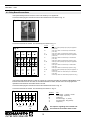
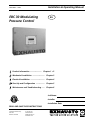
Installation & Operating Manual
3002180EU 10.08
EBC 30 Modulating
Pressure Control
EU
Product Information ........................ Chapter 1 + 2
Mechanical Installation ......................... Chapter 3
Electrical Installation ............................. Chapter 4
Start Up and Configuration .................. Chapter 5
Maintenance and Troubleshooting ...... Chapter 6
Job Name:
ERTEK
INT
CM
C
LISTED
Installer:
US
Installation Date:
READ AND SAVE THESE INSTRUCTIONS!
EXHAUSTO Inc.
1200 Northmeadow Pkwy.
Suite 180
Roswell, GA 30076
P: 770.587.3238
F: 770.587.4731
T: 800.255.2923
[email protected]
us.exhausto.com
3002180EU 10.08
1. Product Information
1.1 Function................................................................................................3
1.2 Shipping................................................................................................3
1.3 Warranty................................................................................................3
1.4 EBC 30 Control Components................................................................3
2. Specifications
2.1 Dimensions & Capacities.......................................................................5
3. Mechanical Installation
3.1 Location.................................................................................................6
3.2 Mounting of Control...............................................................................6
3.3 Mounting of Transducer .......................................................................7
3.4 Installation of Stack Probe (if applicable) .............................................7
3.5 Installation of Outdoor Pressure Probe (if applicable)...........................8
4. Electrical Installation
4.1 General.................................................................................................9
4.2 Relay Board Connections...................................................................10
4.3 Wiring of XTP Sensor.......................................................................... 11
4.4 Wiring of the Control for Priority Operation.......................................... 11
5. Startup and Configuration
5.1 Sequence of Operation.......................................................................12
5.2 Pre-Operation Inspection....................................................................13
5.3 Key Panel Identification and Operation...............................................13
5.4 Initiation of Control..............................................................................14
5.5 Basic Control Set-up...........................................................................14
5.6 Detailed Control Programming............................................................16
5.7 Programming Sequence.....................................................................17
6. Maintenance and Troubleshooting
............................................................................................................18
Symbol Legend:
The following terms are used throughout this manual to bring attention
to the presence of potential hazards or to important information
concerning the product.
Caution: Indicates an imminent hazardous situation
which, if not avoided, may result in personal injury or
property damage.
Danger: Indicates an imminent hazardous situation
which, if not avoided, will result in death, serious injury or
substantial property damage.
TO REDUCE THE RISK OF FIRE, ELECTRICAL SHOCK OR INJURY TO PERSONS,
OBSERVE THE FOLLOWING:
How to use this manual
1. Use this unit in the manner intended by the manufacturer. If you have questions, contact the manufacturer at the address or telephone number listed on the front of the manual.
2. Before servicing or cleaning the unit, switch off at service panel and lock service panel to prevent power from being switched on accidentally.
3. Installation work and electrical wiring must be done by a qualified person(s) in accordance with applicable codes and standards.
4. Follow the appliance manufacturer’s guidelines and safety standards such as those published by the National Fire Protection Associations (NFPA), and the American Society for Heating, Refrigeration and Air Conditioning Engineers (ASHRAE), and the local code authorities.
5. This unit must be grounded.
This installation manual does not contain any system design
documentation. System design documentation is available from any
authorized EXHAUSTO representative.
Accessories, fans and variable frequency drives are not covered by
this manual. Please refer to these component’s individual manuals.
3002180EU 10.08
1. Product Information
1.1 Function
Use
The EBC 30 is a true PID-based fan speed control used to maintain a constant pressure or draft in a venting system. It can be used with EXHAUSTO RS, RSV, RSIF, RSIB, BESF and BESB models to control single phase, 230 VAC, motors directly and three-phase, 400-480VAC, motors indirectly via a VFD (variable frequency drive) that adjusts the motor speed.
The intended use of the control includes, but is not limited to:
• Controlling combustion air supply system.
• Controlling the draft in mechanical draft system serving individual or multiple heating appliance systems.
• Controlling the damper position in a Modulating Over-Draft System to ensure proper draft is maintained in individual or multiple heating appliance systems.
• Controlling the duct pressure in dryer venting systems.
• Controlling the duct pressure in ventilation systems.
The EBC 30 can simultaneously control an exhaust fan, an intake fan or a draft damper. Any two of these can be controlled simultaneously or they can be controlled individually.
Use of the control is not restricted to any type of fuel or type of heating appliance, dryer or venting application.
The unit features “Plug-and-Play” to automatically monitor all terminals and register components attached to the control during initial start-up. It comes pre-programmed from the factory, but can be further programmed in the field, if needed. The control will allow continuous or intermittent operation of a mechanical draft fan.
The control has an integrated safety system to assure the heating appliance will shut down in case of fan failure or control failure. A unique Priority Operation function will probe the operating conditions and allow as many appliances as possible to operate without fan assistance, provided the operation is considered safe by the integrated safety system. The EBC 30 has six (6) heating appliance interlock circuits as standard but can be expanded in multiples of four (4) with the use of an additional relay board or the ES 12, Relay Control.
See Chapter 5.1 for the control’s sequence of operation.
The control can be operated with a manual reset function (reset button) or an automatic reset function. A self-
diagnostic panel with LED’s monitors all connection terminals for easy service and troubleshooting. The EBC 30 can also operate in manual mode where the user sets the constant speed. Provided the integrated safety system is satisfied, interlocked heating appliances are allowed to operate. A Bearing Cycle Activation function rotates the fan motor(s) once every 24 hours in case the fan has not been operating during the previous 24 hour period.
Listings
EXHAUSTO’s EBC 30 is tested and listed to the Standard for Industrial Control Equipment, UL Standard 508, 17th Ed. and CSA C22.2 No. 14-95 as well as UL378, Standard for Draft Equipment. It is listed as part of a CASV Chimney Automation System, MCAS Modulating Combustion Air-Supply System, MODS Modulating Over-Draft System and a MDVS Mechanical Dryer Venting System.
1.2 Shipping
The EBC 30 contains the following:
• EBC 30 control unit
• Relay board (optional) • Triac board (optional)
• Silicone tubing
1.3 Warranty
Complete warranty conditions are available from EXHAUSTO, Inc.
• Pressure transducer (XTP)
• Stack probe
• User manual
3002180EU 10.08
1.4 EBC 30 Control Components
The EBC 30 control is built up around a main board that controls all basic functions. In addition, a Triac board and a relay board, are available for special functions. The main board controls draft/exhaust and air supply/
intake functions. It can provide 0-10VDC signals for Variable Frequency Drives (VFDs), an actuator or other devices accepting a 0-10VDC control signal. It also allows interlock of up to 6 appliances for control circuit voltages between 12VAC and 240VAC/12VDC and 240 VDC, and has an integrated Proven Draft Switch (PDS) function. An external PDS is therefore not required.
The main board layout is shown below in Fig. 1:
Fig. 1
Main Board
6
1
4
2
5
3
7
7
1. Mainboard
2. Relay Board or Triac Board (optional)
3. Terminals
4. Fuse protection for mainboard
5. Quick-connect socket to keypad and display
6. Quick-connect socket to add-on board
7. Operating status indicators
Two add-on boards are available. A Triac board is available so the control can operate a 1x230V fan or ventilator without the need for an external drive. A Relay Board is available for applications with more than 6 appliances. The
control can only accept a single add-on board at a time. If there is a need for using the Triac board as well as the Relay board, install the Triac in the EBC 30 and use an ES 12, Relay Box in lieu of the Relay Board.
Board layouts for the Triac and the Relay Boards are shown below in Fig. 2:
Fig. 2
Triac Board
Relay Board
4
4
3
2
5
1
1
1. Terminals
2. Fuse protection
3. Spare fuse
4. Quick-connect plug
5. Operating status indicators
3002180EU 10.08
2. Specifications
2.1 Dimensions & Capacities
EBC 30 Control
Power Supply
V
Amperage
A
Operating Temperature
°C / °F
Range of Operation
Pa / inWC
0-150 / 0-0.6
Tolerance
Pa / inWC
3 / 0.01 +/-10%
Control Signal
mA
Control Relay
Output
6.3
-20 to 50 / -4 to 122
max. 10
Max. 230 VAC / 4A
VAC
VDC
Dimensions
1 x 230 VAC
20-230
0-10
A mm / in
372 / 14.65
B mm / in
280 / 11.03
C mm / in
107 / 4.22
Weight
kg / lbs
4.0 / 8.9
EMC Standard
Emission
EN 50 081-1
Immunity
EN 50 082-2
XTP Sensor
Power Supply
VDC
Amperage
mA
<20
Output
VDC
0-10
Operating Temperature
°C / °F
Tolerance
Pa / inWC
3 / 0.01 +/-10%
Dimensions
D mm / in
120 / 4.7
Weight
0-24
-20 to 60 / -4 to 140
E mm / in
95 / 3.7
F mm / in
134 / 5.3
G mm / in
100 / 3.9
kg / lbs
.4 / .9
H in/mm
108 / 4.25
I in/mm
89 / 3.50
Chimney Probe
Dimensions
3002180EU 10.08
3. Mechanical Installation
3.1 Location
The control and the transducer must be installed inside, preferably in the mechanical room (boiler room). The control does not need to be installed in an enclosure. Fig. 3 shows how the components are connected.
The transducer cannot be mounted inside an airtight enclosure. It uses the boiler room pressure as reference pressure.
Fig. 3
Max. 15 m (50 feet)
Max. 90 m (300 feet)
Max. 90 m (300 feet)
Max. 2 m (6 feet)
3.2 Mounting of Control
The control can be mounted directly on a wall or similar. The mounting holes are located inside the control as shown in Fig. 4. The distance between the control and the transducer should not exceed 90 meters.
Fig. 4
3002180EU 10.08
3.3 Mounting of Transducer
Attention must be paid to the position and location of the transducer. Fig. 5 shows the required position. Failure to follow this instruction may result in an inoperable system.
An XTP-sensor used for sensing draft should be mounted within 2 meters of the stack probe.
An XTP-sensor used for sensing room pressure should be mounted within 15 meters of the Outdoor Pressure Probe.
Fig. 5
3.4 Installation of Stack Probe (if applicable)
The probe (page 5) is inserted into the chimney or stack at the point where the draft should be kept constant. This could be at the appliance outlet, in the vent or similar. Use a 6 mm drill bit to drill a hole in the side of the chimney for the probe. Acceptable positions are shown below.
Fig. 6
Connect the stack probe to the transducer using the silicone tube. Make sure the tube is connected to the proper transducer port as show in Fig. 7.
Fig. 7
3002180EU 10.08
3.5 Installation of Outdoor Pressure Probe (if applicable)
The outdoor pressure probe should be mounted in a location as free as possible from rooftop obstructions. The choice of location should also consider routing of silicone tubing into the building to minimize tubing run on the roof.
Install the probe on an existing structure like a pole, radio or TV antenna mast. Alternately, the “L” shaped bracket can be attached directly to any wall or rooftop.
It is recommended that the full length of tubing, 15 meters, be used. Excess tubing should be coiled at some convenient location rather than be cut off. Longer lengths are available.
Obstructions such as trees, chimneys, signs and buildings can cause turbulence, which result in abnormal and thus inaccurate static pressure. Position the probe as far from the sources of turbulence as possible.
The XTP sensor is connected to the outdoor pressure probe as shown below in Fig. 8.
Fig. 8
3002180EU 10.08
4. Electrical Installation
4.1 General
Danger: Turn off electrical power before servicing. Contact with live electric components can
cause shock or death.
EBC 30 is designed for 1x230VAC power supply only. Fan output is regulating on the neutral side and cannot be connected to other circuits.
The terminals are connected as shown (for additional information go to Chapter 5.1):
Terminal
Use
1
2
3, 4
5, 6
7
8
9, 10
11
12
13, 14
15
16
17, 18
19
20
21, 22
23
24 25,26
27
28
29
30
31 32
33, 34
35, 36
37
38
39
40, 42
41
43, 44
45
46
47
48, 50
49
Power Supply-L1 (Phase)
Power Supply-N (Neutral)
Ground
AUX1 Dry Contact (Normally Open)
Output to Appliance 1 (0-250V, 8A)
AUX1 Input - Boiler 1 Thermostat Input
10-250VAC/DC (Load, Pos.)
AUX1 Input - Boiler 1 Thermostat Input
(Common, Neg.)
AUX2 Dry Contact (Normally Open)
Output to Appliance 2 (0-250V, 8A)
AUX2 Input - Boiler 2 Thermostat Input
10-250VAC/DC (Load, Pos.)
AUX2 Input - Boiler 2 Thermostat Input
(Common, Neg.)
AUX3 Dry Contact (Normally Open)
Output to Appliance 3 (0-250V, 8A)
AUX3 input - Boiler 3 Thermostat Input
10-250VAC/DC (Load, Pos.)
AUX3 Input - Boiler 3 Thermostat Input
(Common, Neg.)
AUX4 Dry Contact (Normally Open)
Output to Appliance 4 (0-250V, 8A)
AUX4 Input - Boiler 4 Thermostat Input
10-250VAC/DC (Load, Pos.)
AUX4 Input - Boiler 4 Thermostat Input
(Common, Neg.)
AUX5 Dry Contact (Normally Open)
Output to Appliance 5 (0-250V, 8A)
AUX5 Input - Boiler 5 Thermostat Input
10-250VAC/DC (Load, Pos.)
AUX5 Input - Boiler 5 Thermostat Input
(Common, Neg.)
AUX6 Dry Contact (Normally Open)
Output to Appliance 6 (0-250V, 8A)
AUX6 Input - Boiler 6 Thermostat Input
10-250VAC/DC (Load, Pos.)
AUX6 Input - Boiler 6 Thermostat Input
(Common, Neg.)
Draft Input - Supply to EXTERNAL switch (24 VDC)
Draft Input - Return from EXTERNAL switch (24 VDC)
Override Input - (positive) - 0-250VAC/DC
Override Input - (common)
Alarm Relay - Dry Contact (Normally Open) Close on Alarm Condition, (0-250VAC, 8A)
VFD1 Relay - Dry Contact (Normally Open) for Exhaust (0-250V)
Output to Exhaust VFD1 - (positive) 0-10V
Output to Exhaust VFD1 - (common)
Power Supply to Exhaust Transducer (positive) - 24VDC
Output to Exhaust Transducer - (common)
Input from Exhaust Transducer - (positive) 0-10V
VFD2 Relay - Dry Contact (Normally Open) for Intake (0-250V)
Output to Intake VFD - (positive) 0-10V
Output to Intake VFD - (common)
Power Supply to Intake Transducer (positive) - 24VDC
Output to Intake Transducer - (common)
Output to Intake Transducer - (positive) 0-10V
0VDC
+24VDC
0VDC
6
9
10
13
14
17
18
21
22
25
26
29
30
33
35
36
39
40
43
44
47
48
8
11
12
15
16
19
20
23
24
27
28
31
32
34
37
38
41
42
45
46
49
50
0VDC
0-10V
0VDC
0-10V
7
+/~
-/~
AUX1
INPUT
+/~
-/~
AUX2
INPUT
+/~
AUX3
INPUT
-/~
AUX4
RELAY
+/~
AUX4
INPUT
-/~
AUX6
RELAY
AUX5
RELAY
+/~
-/~
+/~
AUX6
INPUT
AUX5
INPUT
-/~
DRAFT
INPUT
+/~
ALARM
RELAY
AUX3
RELAY
-/~
OVERRIDE
INPUT
VFD 1
RELAY
VFD1
EXHAUST
XTP1
VFD 2
RELAY
VFD2
0VDC
+24VDC
5
0-10V
4
AUX2
RELAY
0VDC
3
AUX1
RELAY
ALARM
RELAY
SUPPLY
120VAC
60Hz
L1
N
1
2
0-10V
Fig. 9
XTP2
INTAKE
3002180EU 10.08
4.2 Relay Board Connections
If the optional Relay Board is used, the control can handle up to 10 appliances.
Connect the multi plug from the add-on board to the mainboard as show below in Fig. 10.
Fig. 10
Connect the terminals as needed. The terminal layout is shown in Fig. 11:
Fig. 11
51
53
+/~
AUX9
RELAY
AUX8
RELAY
AUX7
RELAY
52
55
54
-/~
56
57
58
+/~
-/~
59
61
+/~
62
-/~
AUX9
INPUT
AUX8
INPUT
AUX7
INPUT
60
AUX10
RELAY
63
65
+/~
64
66
-/~
AUX10
INPUT
Terminal
Use
51, 52
AUX7 Dry Contact (Normally Open) Output to Appliance 7 (0-250V, 8A)
53
AUX7 input - Boiler 7 Thermostat Input 10-250VAC/DC (Load, Pos.)
54
AUX7 input - Boiler 7 Thermostat Input (Common, Neg.)
55, 56
AUX8 Dry Contact (Normally Open) Output to Appliance 8 (0-250V, 8A)
57
AUX8 input - Boiler 8 Thermostat Input 10-250VAC/DC (Load, Pos.)
58
AUX8 input - Boiler 8 Thermostat Input (Common, Neg.)
59, 60
AUX9 Dry Contact (Normally Open) Output to Appliance 9 (0-250V, 8A)
61
AUX9 input - Boiler 9 Thermostat input 10-250VAC/DC (Load, Pos.)
62
AUX9 input - Boiler 9 Thermostat Input (Common, Neg.)
63, 64
AUX1 Dry Contact (Normally Open) Output to Appliance 10 (0-250V, 8A)
65
AUX10 input - Boiler 10 Thermostat Input 10-250VAC/DC (Load, Pos.)
66
AUX10 input - Boiler 10 Thermostat Input (Common, Neg.)
If the optional Triac Board Add-On is used, the control can control fans operating at 1x230VAC. IMPORTANT: If both Exhaust and Intake functions are used, the Triac Board defaults to Intake, but the control can be programed to operate the Triac Board for the Exhaust function as well.
Connect the multi plug from the add-on board to the mainboard as shown in Fig. 10.
Connect the terminals as needed. The terminal layout is shown in Fig. 12.
Fig. 12
67
L1
Terminal
68
69
N
PE
SUPPLY
70
L1
71
67
68
69
70
71
72
72
Nreg PE
MOTOR
Use
Power Supply - L1 (Phase) - 120VAC
Power Supply - N (Neutral)
PE (Ground)
Fan Motor Supply - L1 (Phase)
Fan Motor Supply - Nreg (Neutral)
PE (Ground)
Fan output is regulating on the neutral side and cannot be connected to other circuits.
10
3002180EU 10.08
4.3 Wiring of XTP Sensor
The XTP sensor is wired as shown below. The wiring to the XTP sensor is always the same, while the wiring on the EBC 30 control depends on whether it is to be wired for exhaust or intake operation:
Fig. 13
4.4 Wiring of the Control for Priority Operation
The control features Priority Operation, which is used only in case of a power failure or mechanical failure at the fan location. The feature will automatically evaluate if one or more appliance(s) can operate safely without mechanical draft. This function is constantly monitored by the PDS function and only if the min. draft point is satisfied, will operation be allowed.
On a call for heat, the control will first probe the appliance connected to the AUX1 Input AUX1 Relay terminals, secondly the appliance connected to the AUX2 Input/AUX2 Relay terminals and so on. Consider the operating priority of the appliances when wiring to the control.
List appliance priority here:
Priority
Appliance Type or Number
Connects to terminals
1
AUX1 - Input/Relay
2
AUX2 - Input/Relay
3
AUX3 - Input/Relay
4
AUX4 - Input/Relay
5
AUX5 - Input/Relay
6
AUX6 - Input/Relay
11
3002180EU 10.08
5. Startup and Configuration
5.1 Sequence of Operation
The EBC 30 initializes when 230VAC power is supplied. It checks for the presence of integrated components such as add-on boards and pressure sensors. The Control does not detect Variable Frequency Drives or Damper
Actuators.
- The software version is displayed on the LED screen
- The control checks for intake and exhaust application by sensing current drawn by an Intake or Exhaust XTP properly connected. It then displays Found or Not Found for Exhaust and Intake modes
- The control checks for any add-on modules and displays Relay Found, Triac Found, or Nothing Found.
- The EBC 30 system application is displayed as Intake Only, Exhaust Only, or Intake and Exhaust.
- The differential pressure reading will be (+) or (-) in reference to the type of pressure being maintained. The pressure reading will be displayed to the hundredths decimal place. The display reads ‘NOT USED’ when an XTP sensor is not connected.
Intermittent Operation
In Intermittent Operation, both AUX Input and AUX RELAY connections are made between each appliance and the EBC 30. This allows the Control to start and stop the fan when an appliance is attempting to fire, and to prevent the appliances from operating if proper draft is not met.
- The EBC 30 initiates pressure control when a voltage signal from any of the six appliances is sensed at the AUX INPUT terminals. No electrical path connects the AUX INPUT terminals so no current passes between them. The LED between the AUX INPUT terminals lights when a call for heat voltage is sensed.
- The Control sends a 100% output to the controlled fans in the system via the Fan Control Module for 230VAC fans or the VFD1 (exhaust) or VFD2 (intake) 0-10VDC outputs for 3 phase fans controlled by Variable Frequency Drives.
- The XTP pressure transducers sense the draft between the exhaust stack and the room or between the outside air and the room and send a 0-10VDC signal back to the XTP1 (exhaust) or XTP2 (intake) terminals.
- The current pressure reading is displayed on the EBC 30. It displays INT or EXH then the pressure reading or both if the application is Intake and Exhaust.
- The DRAFT INPUT terminals must be closed by an external Proven Draft Switch or by a manually installed jumper before any appliances are allowed to operate.
- The AUX RELAY contacts will close only for the appliances that are calling for heat when Draft Set Point pressure is met and DRAFT INPUT is closed. When the AUX RELAY closes, the LED between the terminals will light and the appliance will be permitted to operate normally.
- The EBC 30 will individually close the AUX RELAY contacts for other appliances as they call for heat via their AUX INPUT connections while proper draft is maintained.
- The AUX RELAY contacts will open for individual appliances if their AUX INPUT voltage is lost, or open all AUX RELAYS if the draft is not met or no appliance calls for heat.
The EBC 30 modulates draft pressures by increasing or decreasing the fan speed in response to changing pressure signals. The pressure shown on the display is always in inches of water column of relative vacuum draft.
- The Exhaust fan increases speed to increase the draft felt by the appliances.
- The Intake fan increases speed to decrease the draft read on intake only systems.
-
-
Fan speed is controlled by the 0 to 10VDC output signals at VFD1 & VFD2 terminals where 10VDC is maximum speed.
The Fan Control Module sends 0 to 230VAC to control single phase fans when they are used. The FCM defaults to control the Intake fan when both Intake and Exhaust applications are used.
If the EBC 30 draft reading is out of acceptable range (64% deviation) for 15 seconds, the control will go into Alarm status and open all of the AUX RELAY contacts that shut down the appliances. When draft is met again, it will function as stated above.
12
3002180EU 10.08
Continuous Operation
For Continuous Operation, Dip Switch 1 on the back of the display card on the EBC 30 door must be in the Up/On position. AUX INPUT connections are not used since the Control always attempts to maintain the pressure set point regardless of appliance status. The AUX INPUT LEDs remain lit in Continuous operation and all other EBC 30 functions remain the same as in Intermittent Operation.
5.2 Pre-Operation Inspection
After mounting and wiring has been completed, check the control for the following items before applying power:
•
Check for wiring errors.
•
Verify that there are no wiring chips, screws, etc. remaining inside the controller.
•
Check that all screws and terminal connections are tight.
•
Verify that no exposed wire ends are touching other terminals.
5.3 Key Panel Identification and Operation
When AC power is applied to the control, the keypad panel display will show the following:
Fig. 13
The keypad part names and functions are:
PROG
PROGRAM KEY. Used to access the menu - press for 3 seconds to get to the Quick-menu.
RESET
RESET KEY. Key used for resetting control and fault codes. Also used to accept programming
changes and exit the programming mode.
DOWN KEY. Used to decrease the value of a parameter.
UP KEY. Used to increase the value of a parameter.
DECELERATION INDICATOR. When yellow light is lit, it indicates decreasing fan speed.
DOWN
UP
ACCELERATION INDICATOR. When yellow light is lit, it indicates increasing fan speed.
ALARM INDICATOR. When red light is lit, it indicates an error that must be corrected.
ALARM
13
3002180EU 10.08
5.4 Initiation of Control
When power is supplied to the control it will go through a start-up procedure to detect and check all components and appliances installed. During this procedure the display will show the following:
SOFTWARE VERSION 2.12
EXHAUST SENSOR
INTAKE SENSOR
ADD ON - EXT TRIAC FOUND
APPLICATION
EXH ONLY (or INT ONLY)
EXH ON or OFF
INT OFF or ON
The control is ready. The major functions can now be programmed using the Quick-menu.
5.5 Basic Control Set-up
Once power is turned ON the control can be programmed. Most parameters are programmed at the factory and do not need to be changed. There are 9 parameters that can be programmed/set prior to operation, and they can be accessed through the Quick-Menu.
Q1 SET EXHAUST
For setting the draft or exhaust pressure. Although the value, when measured in the field, is negative pressure it shows up as a positive value on the display. The lowest possible value is 2.5 Pa. Most applications require a setting in the range of 2.5 Pa to 25 Pa. Atmospheric appliances (Category I) are always in the low range, while all other appliances can be anywhere.
The %-value indicates the relative setting of the total range of the sensor.
There is no need to set this value, if the control is used to control the supply of combustion air.
14
3002180EU 10.08
Q2 EXHAUST OPERATING MODE
The control can operate the fan(s) in either “continuous” or “intermittent” mode. The mode can be changed via the display. The display only shows the chosen mode. The mode can be overridden by the dipswitch inside the cover on the print board. If switches are all in ON positions the control will act as there were a call for heat for all appliance at all times. This will disable pre-purge, post-purge and prime functions. This is a function that is beneficial for MODS, MCAS operations and for testing/troubleshooting.
In “continuous” mode the fan operates continuously. During times when the heating appliance(s) is not operating, the fan will still operate although at its lowest capacity. Some exhaust will be pulled through the appliance. The chimney is always primed and there is no real need for pre- and post-purge functions. The energy consumption in this mode is minimal.
In “intermittent” mode the fan only operates if at least one appliance is operating. When no appliance(s) is operating the fan shuts down. In this mode, pre- and post-purge functions are very important and must be set. This mode offers the lowest energy consumption.
If a heating system operates constantly, or the time between cycles is very short (less than 5-10 minutes), “continuous” mode should be considered. Otherwise, “intermittent” mode should be selected.
There is no need to set this value, if the control is used to control the supply of combustion air.
If used with a damper actuator, set for continuous operation.
Q3 SET EXHAUST PRE-PURGE
When operating in “intermittent” mode it is important to set the pre-purge. Pre-purge is the period from when there is a call for heat until the control allows the appliance to start assuming the fan is operating at the proper capacity. The setting can be anywhere from 0 to 1800 seconds.
There is no need to set this value, if the control is used to control the supply of combustion air.
Q4 SET EXHAUST POST-PURGE
When operating in “intermittent” mode it is important to set the post-purge. Post-purge is the period from when the appliance shuts down until the control allows the fan to shut down assuming there are no more products of combustion in the chimney system. The setting can be anywhere from 0 to 1800 seconds. There is no need to set this value, if the control is used to control the supply of combustion air.
Q5 SET INTAKE
For setting the room pressure. The lowest possible value is 2.5 Pa. Most applications require a setting of 25 Pa.
The %-value indicates the relative setting of the total range of the sensor.
There is no need to set this value, if the control is used to control the draft or exhaust pressure.
Q6 INTAKE OPERATING MODE
The control can operate the fan(s) in either “continuous” or “intermittent” mode. The display only shows the chosen mode. See also Q2 about the dipswitch, which can be very beneficial for the supply of combustion air or make-up air, especially where there are chillers, fans etc. that consume air. In “continuous” mode the supply fan operates continuously. During times when the heating appliance(s) is not operating, the supply fan will still operate although at its lowest capacity. Some pressurization of the mechanical room may occur. The room is always primed and there is no real need for pre- and post-purge functions. The energy consumption in this mode is minimal.
In “intermittent” mode the supply fan only operates if at least one appliance is operating. When no appliance(s) is operating the supply fan shuts down. In this mode, pre- and post-purge functions are very important and must be set. This mode offers the lowest energy consumption.
If a heating system operates constantly, or the time between cycles is very short (less than 5-10 minutes), “continuous” mode should be considered. Otherwise, “intermittent” mode should be selected.
There is no need to set this value, if the control is used to control the draft or exhaust pressure.
15
3002180EU 10.08
Q7 SET INTAKE PRE-PURGE
When operating in “intermittent” mode it is important to set the pre-purge. Pre-purge is the period from when there is a call for heat until the control allows the appliance to start assuming the supply fan is operating at the proper capacity. The setting can be anywhere from 0 to 1800 seconds.
There is no need to set this value, if the control is used to control the draft or exhaust pressure.
Q8 SET INTAKE POST-PURGE
When operating in “intermittent” mode it is important to set the post-purge. Post-purge is the period from when the appliance shuts down until the control allows the fan to shut down assuming there are no more products of combustion in the chimney system. The setting can be anywhere from 0 to 1800 seconds. There is no need to set this value, if the control is used to control the draft or exhaust pressure.
Q9 ROTATION CHECK
There are two values available “ON” or “OFF”.
In the ON mode, the control will activate all fans connected to the control when turned on, and operate them at a very low speed so proper rotation can be easily verified when 3-phase motors are used. If improper rotation is experienced appropriate action can be taken. Once proper operation has been verified, press the RESET button to accept all settings.
The above procedure is only required during the initial installation or if a motor or variable frequency drive has been replaced.
If a power failure has occurred there is no need to check rotation and the RESET button can be pressed.
In the OFF mode, the control does not activate all fans in low speed mode but will let them operate at any speed setting. OFF mode can be used after the initial installation.
To access the Quick-Menu, press the PROG key for 3 seconds. The figure on page 16 shows the sequence of programming.
5.6 Detailed Control Programming
The EBC 30 control has a detailed sub-menu for individual parameter settings. Please contact EXHAUSTO if you need a more detailed programming guide.
To view current alarm description inside service menu press PROG and it goes to parameter 51
”current alarm” (if alarm condition is present).
Must go to “5 alarm” to exit.
16
3002180EU 10.08
5.7 Programming Sequence
NOTES
Press key for 3 seconds
to access menu
PROG
Q1 SET EXHAUST
* 2.5 Pa
PROG
Q1 SET EXHAUST
* 2.5 Pa
PROG
The pressure can be set
between 3.0 and 148.5
(Default is 3.0)
Available selections are:
"continuous" and "intermittent".
Q2 EXH OPER MODE
* CONTINUOUS
PROG
Q2 EXH OPER MODE
* CONTINUOUS
PROG
Q3 SET EXH PRE-PURGE
* 60 s
PROG
Q3 SET EXH PRE-PURGE
* 60 s
PROG
Values can be set from 0 to
360 seconds.
Q4 SET EXH POST-PURGE
* 60 s
PROG
Q4 SET EXH POST-PURGE
* 60 s
PROG
Values can be set from 0 to
360 seconds.
Q5 SET INTAKE
* 2.5 Pa
PROG
Q5 SET INTAKE
* 2.5Pa
PROG
The pressure can be set
between 3.0 and 148.5
(Default is 3.0)
Available selections are:
"continuous" and "intermittent".
Q6 INT OPER MODE
* CONTINUOUS
PROG
Q6 INT OPER MODE
* CONTINUOUS
PROG
Q7 INT PRE-PURGE
* 60 s
PROG
Q7 INT PRE-PURGE
* 60 s
PROG
Values can be set from 0 to
360 seconds.
Q8 INT POST-PURGE
* 60 s
PROG
Q8 INT POST-PURGE
* 60 s
PROG
Values can be set from 0 to
360 seconds.
Q9 ROTATION CHECK
* OFF
PROG
Q9 ROTATION CHECK
* OFF
PROG
Values can be ON or OFF.
Saves all settings and
displays default display.
RESET
17
3002180EU 10.08
6. Maintenance and Troubleshooting
Most terminal connections are monitored for proper operation. LED lights indicate operating status. If a light is lit, it indicates everything is functioning properly while a light out indicates a problem on the circuit it monitors.
In addition, fault codes are shown on the display The fault codes are:
Display
Explanation
A1 Draft Exhaust
Insufficient draft pressure. Can be caused by:
1. Chimney fan does not have enough capacity
2. Mechanical or electrical fan failure
3. Blocked chimney
4. Introduction of excessive dilution air
5. XTP sensor not responding correctly
Insufficient intake air supply. Can be caused by:
1. Supply fan does not have enough capacity
2. Mechanical or electrical fan failure
3. Blocked air inlet our louver
4. Excessive exhaust from exhaust fans located in mechanical room
Indicates there has been a power fault
Indicates a disconnected signal from the XTP-Sensor on the exhaust
side to the control Can be caused by:
1. Loose connections
2. Faulty XTP-sensor
3. Faulty controller
Indicates a disconnected signal from the XTP-sensor on the intake side
to the control. Can be caused by:
4. Loose connections
5. Faulty XTP-Sensor
6. Faulty controller
Indicates that the control has not been able to release the heating
appliance(s) within 15 minutes.
Indicates alarm has been ignored
Missing signal from PDS-function. Indicates a faulty function.
A2 Draft Intake
A3 Power Fault
A4 XTP-Exhaust
A5 XTP-Intake
A6 Error Start
A7 Alarm Override
A8 Draft Input
Other fault possibilities are shown below:
Red alarm on main board is lit
Red alarm diode flashes
Yellow light (UP) is lit continuously
Yellow light (DOWN) is lit continuously
Indicates a malfunction. Can be caused by:
1. No communication between main board and display.
Make sure the cable is connected. This error will shut down the
appliances within 20 seconds.
Indicates the control operates the appliances in prioritized mode.
Indicates the control is accelerating the fan speed. If it stays on
constantly it indicates a system fault. This can be caused by
1. Wiring problems
2. A clogged tube or probe
3. A leaking chimney system
4. Inadequate fan capacity
Indicates a malfunction. Can be caused by:
1. If a Triac Board is installed this is an indication that the neutral
connection is shared with other equipment. It must be a dedicated line
between the control and the fan.
18
3002180EU 10.08
EXHAUSTO EBC 30 Factory Settings
Menu
2
Sub-Menu
21
22
23
24
25
26
3
31
32
33
34
35
36
4
5
6
231
232
241
242
251
252
261
262
263
264
265
266
267
331
332
341
342
351
352
361
362
363
364
365
366
367
41
42
43
51
52
53
61
62
63
64
65
621
622
623
624
625
626
627
628
629
641
642
643
651
652
Function
EXHAUST
Draft Set Point
Operation Mode
PRE-PURGE
Time
Operation Mode
POST-PURGE
Time
Operation Mode
SENSOR
Min. Pressure
Max . Pressure
PARAMETERS
Alarm Limit Draft
Alarm Delay
Min. Voltage
Max. Voltage
Xp
Ti
Pressure Type
INTAKE
Intake Set Point
Operation Mode
PRE-PURGE
Time
Operation Mode
POST-PURGE
Time
Operation Mode
SENSOR
Min. Pressure
Max . Pressure
PARAMETERS
Alarm Limit Draft
Alarm Delay
Min. Voltage
Max. Voltage
Xp
Ti
Pressure Type
DISPLAY
Language
Units
Display Lights
ALARM
Alarm status
Alarm log
RESET
SERVICE
Version No.
I/O
BURNER I/O*
RELAY BOARD*
EXHAUST I/O*
INTAKE I/O*
TRIAC BOARD
DRAFT INPUT
Override input
Alarm Relay
Application
Triac board
OVERRIDE
Draft Mode
Intake Mode
Alarm Mode
OPTIONS
Prioritized Duty
Bearing Activation
Display
EXHAUST
SET EXHAUST
OPERATION
PREPURGE
TIME
SPEED MODE
POST PURGE
TIME
SPEED MODE
SENSOR
RANGE MIN
RANGE MAX
PROPERTIES
ALARM LIMIT
ALARM DELAY
SPEED MIN
SPEED MAX
EXHAUST Xp
EXHAUST Ti
PRESSURE MOD
INTAKE
SET INTAKE
OPERATION
PREPURGE
TIME
SPEED MODE
POST PURGE
TIME
SPEED MODE
SENSOR
RANGE MIN
RANGE MAX
PROPERTIES
ALARM LIMIT
ALARM DELAY
SPEED MIN
SPEED MAX
INTAKE Xp
INTAKE Ti
PRESSURE MOD
DISPLAY
LANGUAGE
UNIT
LIGHT
ERROR
ERROR LOG
RESET
SERVICE
VERSION
I/O-VIEW
AUX OUT XXX XXX
RELAY OUT XXXX
EXH XTP x.xV OFF
INT XTP x.xV OFF
TRIAC BOARD
DRAFT INPUT
OVERRIDE IN
ALARM OUTPUT
APPLICATION
TRIAC BOARD
OVERRIDE
EXHAUST
INTAKE
ALARM MODE
OPTION
PRIORITY
BEARING CYCLE
19
Range
Default
3%-95% of sensor range
Continuous / Intermittent
0-1800
0-1800
-500-+500Pa
0-1000Pa
0.1
FIX 100 %
0
150Pa
64%
15
15%
100%
15
8
Negative
3%-95% of sensor range
Continuous / Intermittent
0-1800
0
Variable
50-80%
0-120s
0-MENU264
MENU263-100%
0-30
0-30
(+) or (-)
0
0
0.01
FIX 100 %
0-1800
See text
Variable
-500-+500Pa
0-1000Pa
150Pa
100-300%.
0-120s
0-MENU364
MENU363-100%
0-30
0-30
(+) or (-)
0
0
0
300%
15s
20%
100%
15
15
Negative
Eng/Fr./Sp.
Pa/inWC
ON/OFF
English
inWC
ON
MAN/AUT
AUT
INTAKE/ EXHAUST
OFF/ NORMAL/ MAX
OFF/ NORMAL/ MAX
ON/OFF
MAX
NORMAL
OFF
ON/OFF
ON/OFF
ON
ON
3002180EU 10.08
Resetting to Factory Defaults
PROG
NOTES
Q1 SET EXHAUST
* 2.5 Pa
Q10 SERVICE MENU
PROG
Press PROG key for 3 seconds
to access menu
Scroll to [ Q10 SERVICE MENU ]
and press PROG
2 EXHAUST
6 SERVICE
61 VERSION
66 FACTORY
* NO
PROG
Scroll to 6 SERVICE and press PROG
66 FACTORY
* NO
PROG
Scroll to 66 FACTORY and press PROG
66 FACTORY
* YES
PROG
Change NO to YES and press PROG
Remove supply power to control. Wait 30 seconds and reapply power.
Control is now reset to factory default.
User Settings
Please record and keep the following information. It will ease servicing the control after installation.
Q1 EXHAUST setting
Q2 EXHAUST Operating Mode
Pa
Continuous/Intermittent (circle one)
Q3 EXHAUST Pre-purge
seconds
Q4 EXHAUST Post-purge
seconds
Q5 INTAKE setting
Q6 INTAKE Operating Mode
Pa
Continuous/Intermittent (circle one)
Q7 INTAKE Pre-purge
seconds
Q8 INTAKE Post-purge
seconds
Q9 ROTATION CHECK
EXHAUSTO Inc.
1200 Northmeadow Pkwy.
Suite 180
Roswell, GA 30076
P: 770.587.3238
F: 770.587.4731
T: 800.255.2923
[email protected]
us.exhausto.com
Yes/No (circle one)