1
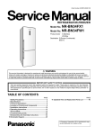
1
WYJ6 — User’s Manual rev. 1.0
WYJ6 — User’s Manual rev. 1.0
Krzysztof Mazur
1
Introduction
1.1
Quick guide
Installation in AR-2c dataloggers:
1. Enable battery backup using switch near battery.
2. Set appropriate input voltage range using 24V jumper.
3. Set bus address to 14 — A2=1, A1=1, A0=0.
4. Enable Legacy Mode — S1 jumper should be open.
WARNING: If external power supply is not present for a long time it’s recommended to disable
battery backup. The battery should be recharged every 12 months by enabling battery backup and connecting
external power supply for at least 24 hours.
1.2
New revisions
This is the revision 1.0 of this specification. The first number is the major revision number. The major
revision number identifies the hardware revision. The second number is the minor revision used to specify
the version of the documentation of for the same hardware.
Latest revision of this document is available at http://www.microster.pl/doc/wyj6.
1.3
Copyright
Copyright © 2011, 2012, 2013 Krzysztof Mazur.
This document is licensed under a Creative Commons Attribution-Share Alike 3.0 United States
License.
2
General description
The WYJ6 is a BUSMAT card that combines up to 9 MiB battery-backed paged Random Access Memory (RAM), watchdog and general purpose digital inputs and outputs. The card provides both new
interface compatible with ARBus 0.0 providing PCI-compatible configuration, and legacy interface for
full compatibility with original WYJ5 cards.
The RAM controller is compatible with RAMBAT 0.0 interface. The memory is accessed using
32 KiB pages. The page content is accessible by Paged RAM Access Window (BAR1). The visible page
can be selected by Rambat Page (RAMBAT_PAGE) register. In legacy mode the last page is also accessible
by separate Non-paged RAM Access Window (BAR2).
The rambat page size is equal to Base Address Region 1 size. The number of pages can be detected by
writing maximal value to Rambat Page (RAMBAT_PAGE) register and read it back as maximal supported
page.
3
Ordering guide
The WYJ6 card is available in the following versions:
Model
Bus
SubsystemID
Memory
WYJ6-5M
BUSMAT
0002
5 MiB
WYJ6-9M
BUSMAT
0003
9 MiB
Comments
2
WYJ6 — User’s Manual rev. 1.0
4
Technical specifications
Bus interface
BUSMAT
Bus frequency
up to 16.7 MHz
Form factor
BUSMAT
Power supply voltage
5 V ±5%
Power supply current
up to 200 mA
Number of digital inputs
1
Number of digital outputs
2
Battery-backed SRAM memory size
5 MiB or 9 MiB
Battery backup time
at least 7 days
4.1
Recommended operating conditions
Parameter
Min
Typ
Max
Unit
Supply voltage
4.75
5
5.25
V
Temperature
5
4.2
Input/Output signals
4.3
External connector
55
Pin
Symbol
1
PKAR_ON
PKAR relay — normally open contact
2
PKAR_OFF
PKAR relay — normally closed contact
3
PKAR_C
4
N_IN
N input signal
5
N_GND
N input ground
6
PSAR
PSAR relay
7
PSAR
PSAR relay
8
5V
5 V output
9
NC
Not connected
10
GND
4.4
N input
◦
C
Description
common signal for PKAR relay
5 V output ground
The N digital input can be configured as 24 V input or 110 V input using 24 V jumper (see section 5.1).
Input type
DC
Input current flow direction
sink
Input voltage
24 V or 110 V
Input voltage tolerance
±35%
Input current
0.9 mA to 6 mA
3
WYJ6 — User’s Manual rev. 1.0
Parameter
Min
Low-level input current
0
High-level input current
0.9
Typ
Voltage drop
Unit
0.3
mA
3
6
mA
3.3
4.3
V
24 V
Parameter
4.5
Max
110 V
Unit
Min
Typ
Max
Min
Typ
Max
Input resistance
0
8
8.4
22
32
34
Isolation voltage
1000
kΩ
1000
V
PSAR and PKAR relays
Max. Switching Voltage
125 V DC or 380 V AC
Max. Switching Current
8A
Max. Switching Power
300 W
4.6
5
5.1
5V output
Parameter
Min
Typ
Max
Unit
Output voltage without load
4.5
5
5.5
V
Output voltage with 5 mA load
4
4.5
5
V
Output impedance
99
102
105
Ω
Configuration
Input voltage selection
The N signal input voltage range can be selected using 24V jumper.
5.2
24V
Input voltage
0
110 V
1
24 V
Address selection
The WYJ6 card ARBus device number can be configured using ADDR jumper. The most significant bits
of 4-bit number is hard-wired to 1.
4
WYJ6 — User’s Manual rev. 1.0
ADDR
DevNo
2
1
0
0
0
0
8
0
0
1
0
1
0
Initial Legacy Mappings
Configuration Memory
BAR0
BAR1
BAR2
0xdc000
0xdc400
0xa0000
0xb0000
9
0xdc800
0xdcc00
0xa0000
0xb0000
0
10
0xdd000
0xdd400
0xa0000
0xb0000
1
1
11
0xdd800
0xddc00
0xa0000
0xb0000
1
0
0
12
0xde000
0xde400
0xa0000
0xb0000
1
0
1
13
0xde800
0xdec00
0xa0000
0xb0000
1
1
0
14
0xdf000
0xdf400
0xa0000
0xb0000
1
1
1
15
0xdf800
0xdfc00
0xa0000
0xb0000
The WYJ6 revision 0 have Device number hard-wired to 14.
5.3
Installed memory size
The WYJ6 cards are available in 5 MiB or 9 MiB versions. The installed memory size must be configured
using S2 jumper.
S2
Memory Size
Number of pages
Page size
0
5 MiB
160
32 KiB
1
9 MiB
288
32 KiB
The WYJ6 revision 0 have S2 jumper hard-wired to 1.
5.4
Legacy Mode
By default the WYJ6 card is fully compatible with WYJ5 cards. This however cause resource conflicts
when multiple cards are present on the same bus or cause problems when the system does not use WYJ6
card’s watchdog. To avoid such problems the Legacy Mode can be disabled by S1 switch.
S1
I/O and Memory Resources
Watchdog
0
pre-configured
enabled
1
disabled
disabled
See 5.2 section for pre-configured Memory Resources mapping in Legacy Mode.
The WYJ6 have built-in watchdog and can drive BUSMAT’s RST# pin. The watchdog is enabled by
default in Legacy Mode.
6
6.1
Host interface
Configuration Registers
The WYJ6 card have 256-bytes of PCI-compatible Configuration Address Space (see Fig. 1). For operating systems that supports ARBus access for this address space is provided by bus interface driver. If
not you can access those registers directly at Configuration Memory address specified in section 5.2.
5
WYJ6 — User’s Manual rev. 1.0
Configuration Register Summary
Offset
Type
0x0
RO
0x2
Reset value
Description
VendorID
0xff00
6.1.1
RO
DeviceID
0x000a
6.1.2
0x4
RW
Command
0x0000
6.1.3
0x6
RO
Status
0x0000
6.1.4
0x8
RO
RevisionID
0x01
6.1.5
0x9
RO
ProgIF
0x00
6.1.6
0xa
RO
Sub-class
0x80
6.1.7
0xb
RO
Base Class
0x05
6.1.8
0xe
RO
Header Type
0x00
6.1.9
0x10
RW
Base Address Register 0
0x00000000
6.1.10
0x14
RW
Base Address Register 1
0x00000000
6.1.11
0x18
RW
Base Address Register 2
0x00000000
6.1.12
0x2c
RO
SubsystemVendorID
0xff00
6.1.13
0x2e
RO
SubsystemID
−
6.1.14
0x40
WO
Watchdog disable
−
6.1.15
Offset
Register
3
2
1
0
0x00
Device ID (0x000a)
Vendor ID (0xff00)
0x04
Status
Command
0x08
Base Class (0x05)
Sub-class (0x00)
ProgIF (0x00)
Revision ID (0x01)
0x0c
Reserved
Header Type (0x00)
Reserved
Reserved
0x10
Base Address Register 0
0x14
Base Address Register 1
0x18
Base Address Register 2
0x1c–0x2b
Reserved
0x2c
Subsystem Device ID
0x30–0xef
Reserved
0x40
Reserved
0x44–0xef
0xf0
Subsystem Vendor ID (0xff00)
Watchdog
Reserved
0x53
0x42
0x52
0xf4
Reserved
0xf8
Reserved
0xfc
Reserved
Figure 1: WYJ6 Configuration Address Space.
0x41
6
WYJ6 — User’s Manual rev. 1.0
6.1.1
Vendor ID
Offset
Width
Type
Reset value
0x00
16 bit
RO
0xff00
The Vendor ID identifies the manufacturer of the device. For this device this register is equal to
0xff00.
6.1.2
Device ID
Offset
Width
Type
Reset value
0x02
16 bit
RO
0x000a
The Device ID identifies the device model. For this device this register is equal to 0x000a.
6.1.3
Command
Offset
Width
Type
Reset value
0x04
16 bit
RW
0x0000 or 0x0003 for Legacy Mode
15
14
13
12
11
10
9
8
7
6
5
4
3
2
1
0
RESV
MEM
IO
RO
RW
RO
Command Register Bit Descriptions
Bit
Name
Description
15–2
RESV
Reserved.
1
MEM
Memory Space. Set to enable decoding of Memory Regions
0
IO
IO Space. Set to enable decoding of Legacy I/O ports.
6.1.4
Status
Offset
Width
Type
Reset value
0x06
16 bit
RO
0x0000
The Status register is always equal to 0.
6.1.5
Revision ID
Offset
Width
Type
Reset value
0x08
8 bit
RO
1
The Revision ID identifies the revision of the device. The current revision is 1.
7
WYJ6 — User’s Manual rev. 1.0
6.1.6
ProgIF
Offset
Width
Type
Reset value
0x09
8 bit
RO
0x00
The ProgIF register identifies the programming interface in specified class of device. This device
reports programming interface as 0x00.
6.1.7
Sub-class
Offset
Width
Type
Reset value
0x0a
8 bit
RO
0x00
The Sub-class register identifies the sub-class of device. This device uses class 0x05 and sub-class
0x00 — RAM memory.
6.1.8
Base Class
Offset
Width
Type
Reset value
0x0b
8 bit
RO
0x05
The Base Class register identifies the class of device. This device uses class 0x05 — Memory controller.
6.1.9
Header Type
Offset
Width
Type
Reset value
0x0e
8 bit
RO
0x00
The Header Type identifies the type of Configuration Space header. This field is equal to 0x00.
6.1.10
Base Address Register 0
Offset
Width
Type
Reset value
31
0x10
32 bit
RW
0xdf400
30
29
28
27
26
25
24
23
22
21
20
19
18
17
ADDR
RO
15
14
13
12
11
10
RW
9
8
7
6
ADDR
RW
RO
5
4
3
2
1
0
P
TYPE
IO
RO
RO
RO
Base Address Register 0 Bit Descriptions
16
8
WYJ6 — User’s Manual rev. 1.0
Bit
Name
Description
31–4
ADDR
Address. The ADDR sets the bits 31–4 of region 0 base address. Only bits 10 to 19
are configurable. The bits 4 to 9 are hard-wired to 0 indicate 1 KiB region size.
3
P
2-1
TYPE
0
IO
6.1.11
Prefetchable. cleared to indicate non-prefetchable region
Type. 0 — 32-bit base address
IO Space indicator. cleared to indicate Memory Space
Base Address Register 1
Offset
Width
Type
Reset value
31
0x14
32 bit
RW
0xa0000
30
29
28
27
26
25
24
23
22
21
20
19
18
17
16
ADDR
RO
15
14
13
12
11
RW
10
9
8
7
6
5
4
ADDR
RW
RO
3
2
1
0
P
TYPE
IO
RO
RO
RO
Base Address Register 1 Bit Descriptions
Bit
Name
Description
31–4
ADDR
Address. The ADDR sets the bits 31–4 of region 0 base address. Only bits 15 to 19
are configurable. The bits 4 to 14 are hard-wired to 0 indicate 32 KiB region size.
3
P
2-1
TYPE
0
IO
6.1.12
Prefetchable. cleared to indicate non-prefetchable region
Type. 0 — 32-bit base address
IO Space indicator. cleared to indicate Memory Space
Base Address Register 2
Offset
Width
Type
Reset value
0x18
32 bit
RW
0xb0000
This register is available only in Legacy Mode.
31
30
29
28
27
26
25
24
23
22
21
20
19
18
17
ADDR
RO
15
14
13
12
11
RW
10
ADDR
RW
RO
9
8
7
6
5
4
3
2
1
0
P
TYPE
IO
RO
RO
RO
16
9
WYJ6 — User’s Manual rev. 1.0
Base Address Register 1 Bit Descriptions
Bit
Name
Description
31–4
ADDR
Address. The ADDR sets the bits 31–4 of region 0 base address. Only bits 15 to 19
are configurable. The bits 4 to 14 are hard-wired to 0 indicate 32 KiB region size.
3
P
2-1
TYPE
0
IO
6.1.13
Prefetchable. cleared to indicate non-prefetchable region
Type. 0 — 32-bit base address
IO Space indicator. cleared to indicate Memory Space
Subsystem Vendor ID
Offset
Width
Type
Reset value
0x2c
16 bit
RO
0xff00
The Subsystem Vendor ID is assigned by expansion board or subsystem vendor. For this device this
register is equal to 0xff00.
6.1.14
Subsystem ID
Offset
Width
Type
Reset value
0x2e
16 bit
RO
0x0001
The Subsystem ID is assigned by expansion board or subsystem vendor. For this device this register
is equal to 0x0001.
6.1.15
Watchdog disable
Offset
Width
Type
Reset value
0x40
8 bit
WO
—
The Watchdog disable register is used to control the watchdog functionality.
Writing 0x84 to this register enables watchdog auto-refresh. Writing any other value disables autorefresh.
With watchdog auto-refresh enabled the host does not need to refresh watchdog. The power control
is still performed and if WDT jumper is present the RST# pin can be asserted.
6.2
Region 0 — Runtime registers
Runtime registers Register Summary
Offset
Type
Register
Reset value
Description
0x00
RW
Rambat Page (RAMBAT_PAGE)
0x00000000
6.2.1
0x0b
RW
Watchdog Control (RAMBAT_WDT)
0x00
6.2.2
0x0c
RO
Inputs (RAMBAT_INPUTS)
0x00
6.2.3
6.2.1
Rambat Page (RAMBAT_PAGE)
Runtime registers offset
Width
Type
Reset value
0x00
32 bit
RW
0x00000000
10
WYJ6 — User’s Manual rev. 1.0
31
30
29
28
27
26
25
24
23
22
21
20
5
4
19
18
17
1
0
16
PAGE
RO
15
14
13
12
11
10
9
8
7
6
3
2
PAGE
RO
RW
Rambat Page Bit Descriptions
Bit
Name
Description
31–0
PAGE
Rambat Page. The selected page visible in Paged Memory window. This device
supports 160 (5 MiB) or 288 (9 MiB) pages. The written value will be saturated to
159 or 287.
To detect the number of pages host should write 0xffffffff to Rambat Page (RAMBAT_PAGE) register
and read-back Rambat Page (RAMBAT_PAGE) register. The value of the register will be set to the maximal
supported page. The number of pages is equal to maximal supported page plus one. The host driver may
also use just 8 bits or 16 bits of this register and use 0xff or 0xffff for probing the number of pages.
To avoid problems with partial writes of this register the write to the Least Significant Byte clears
all higher bytes. This register must be written from the Least Significant Byte to the Most Significant
Byte.
Note: The last page (159 or 287) is shared with page visible in Non-paged RAM Access Window.
6.2.2
Watchdog Control (RAMBAT_WDT)
runtime registers offset
Width
Type
Reset value
0x0b
8 bit
RW
0x00
7
6
5
4
Reserved
Alarm
Fatal
Reserved
RO
RW
RO
3
Name
Description
7
Reserved
Reserved.
6
Alarm
Alarm relay. Alarm relay control.
5
Fatal
Fatal relay. Fatal relay control.
4
Reserved
3-0
Leds
6.2.3
Reserved.
Leds. Leds control.
Inputs (RAMBAT_INPUTS)
runtime registers offset
Width
Type
Reset value
0x0c
8 bit
RO
0x00
1
Leds
RO
Watchdog Control Bit Descriptions
Bit
2
RW
0
11
WYJ6 — User’s Manual rev. 1.0
7
6
5
4
3
2
1
0
Reserved
Reserved1
N
SW2
SW1
B2
B1
RO
RO
RO
RO
RO
RO
RO
Inputs register Bit Descriptions
Bit
Name
7–6
Reserved
Reserved. Reserved. Read as 3
5
Reserved1
Reserved1.
4
N
3
SW2
Switch 2.
2
SW1
Switch 1.
1
B2
Button 2.
0
B1
Button 1.
6.3
Description
N. General purpose digital input
Region 1 — Paged RAM Access Window
The selected page of rambat memory is visible as Memory Region 1. The visible page can be changed
by setting Rambat Page (RAMBAT_PAGE) register. The page size is equal to memory region size.
6.4
Region 2 — Non-paged RAM Access Window
In Legacy Mode the last page (159 or 287) of rambat memory is visible as Memory Region 2. The page
size is equal to memory region size.
6.5
Legacy registers
The WYJ6 card also provides Legacy registers for compatibility with original WYJ5 cards. Those registers
are accessible as I/O ports.
Using Legacy registers in new drivers is not recommended. Those registers does not provide read-back
functionality and access to those registers have various side-effects.
Legacy registers Register Summary
Offset
Type
0xfd83
WO
0xfd83
0xfd84
6.5.1
Register
Reset value
Description
Legacy Watchdog Control (LEGACY_WDT)
0x00
6.5.1
RO
Legacy Inputs (LEGACY_INPUTS)
0x00
6.5.2
WO
Legacy Page (LEGACY_PAGE)
0x00
6.5.3
Legacy Watchdog Control (LEGACY_WDT)
Shadow of the Watchdog Control (RAMBAT_WDT) register. See section 6.2.2.
6.5.2
Legacy Inputs (LEGACY_INPUTS)
Shadow of the Inputs (RAMBAT_INPUTS) register. See section 6.2.3.
6.5.3
Legacy Page (LEGACY_PAGE)
Runtime registers offset
Width
Type
Reset value
0x00
8 bit
WO
0x00
12
WYJ6 — User’s Manual rev. 1.0
7
6
5
4
3
2
1
0
PAGE
WO
Legacy Rambat Page Bit Descriptions
Bit
Name
Description
7–0
PAGE
Legacy Rambat Page. Selects page visible in Paged Memory window. The mapping
between pages selected by this register is however different than mapping selected by
(RAMBAT_PAGE) register (see section 6.2.1).
For 9 MiB cards the mapping between Legacy Pages is one to one, however only first 256 pages are
accessible. For 5 MiB cards 16 KiB subpages are used. The 32 KiB page is divided into two 16 KiB
subpages: Low subpage (L) and High subpage (H). The first 128 pages are mapped directly so the the
memory can be used as 128 32 KiB pages.
For pages 128–255 higher subpage is also visible at 0–16 KiB offsets. This allows for using memory
also as 256 16 KiB pages.
Table 1: Mapping between Legacy Pages and native pages
Legacy page
A
5 MiB card offset
9 MiB card offset
0–16 KiB
16–32 KiB
0–16 KiB
16–32 KiB
0
0L
0H
0L
0H
1
1L
1H
1L
1H
2
..
.
2L
..
.
2H
..
.
2L
..
.
2H
..
.
126
126L
126H
126L
126H
127
127L
127H
127L
127H
128
0H
0H
128L
128H
129
1H
1H
129L
129H
130
..
.
2H
..
.
2H
..
.
130L
..
.
130H
..
.
254
126H
126H
254L
254H
255
127H
127H
254L
254H
Factory testing
This section describes tests performed on WYJ6 cards after production. The same tests are performed
also after each modification of WYJ6 card.
A.1
Memory testing
The memory is tested on AR-3c dataloggers using rambat-test:
# rambat-test --device bus:device
where bus is the PCI bus number (1 for AR-3c dataloggers), device is the PCI device number selected
by ADDR switch (see section 5.2). For instance the card with ADDR=8 can be tested using:
WYJ6 — User’s Manual rev. 1.0
# rambat-test --device 1:8
13