1
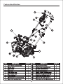
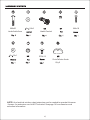
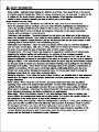
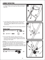
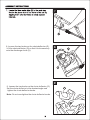
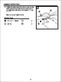
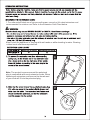
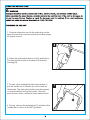
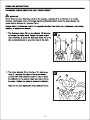
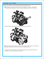
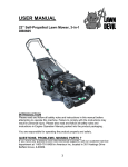
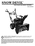
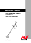
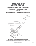
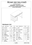
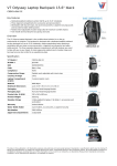
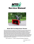
Questions, problems, missing parts? If you have questions about this product or need
technical support, call the Amerisun customer service department at 1-800-791-9458.
Also contact Amerisun at Amerisuninc.com and e-mail [email protected]"
Feature Indentification
5
20
20
Clearing width and depth: Approx. 46 cm x 20 cm (18 in. x 8 in.)
Max. throwing distance: 10 m (30 ft.)
Feature Identification
M8x50
Handle Saddle Screw
6x 13x1
M4x18
8x 28x3
Handle Camlock
BT4x12
Chute Deflector Knobs
Qty.2
NOTE: An electrical outdoor rated extension cord is needed to operate this snow
thrower. An extension cord is NOT included. See page 14 for extension cord
selection information.
(usually orange color). The extension cord MUST be of the proper gauge size depending
on it's length (see page 14). To prevent the extension cord from disconnecting during
operation, tie it around the top right side of the middle frame before connecting it to the
snow thrower as shown in Figure 2 on page 14.
Before beginning assembly of product, make sure all parts are present. Compare parts in
package to hardware contents on page 4.
Tools required for assembly Phillips screwdriver and 7 mm wrench.
1. Position the middle frame (B) with the arrow on the
"UP" decal pointing UP when viewed from rear.
Align the middle frame mount holes to the holes on
the lower frame (A).
Note: If middle frame (B) is installed upside-down,
the chute crank rod eye-bolt will not line up when
installing the chute crank rod.
UP
Decal viewed from rear.
2. Insert the handle saddle screw (AA) with the metal
washer (BB) into the aligned holes on each side. The
metal washer (BB) should be inserted outside of the
frame.
Note: Avoid damaging screw threads during installation.
M8x50 Handle Saddle Screw
8x 28x3
3.Use the handle camlocks (CC) to secure the connection.
The handle camlocks (CC) should be inserted outside of
the frame. Tighten the camlock just snug to the handle.
NOTICE: To avoid breaking the camlock, Do Not overtighten
the camlock. The camlock tightens as it is pivoted when
clamped. If the camlock is initially threaded too tight and then
clamped, it will break. Only slight clamping pressure is
required to hold the handle in place.
Handle Camlock
4. Position upper frame (C) as shown (handle bar up)
in image 4. Align mount holes with holes on middle
frame (B)
5. Insert the handle saddle screw (AA) with the metal
washer (BB) into the aligned holes on each side.
The metal washer (BB) should be inserted outside
of the frame.
Note: Avoid damaging screw threads during installation.
M8x50 Handle Saddle Screw
8x 28x3
6.Use the handle camlocks (CC) to secure the
connection. The handle camlocks (CC) should be
inserted outside of the frame. Tighten the camlock
just snug to the handle.
NOTICE: To avoid breaking the camlock, Do Not
overtighten the camlock. The camlock tightens as it is
pivoted when clamped. If the camlock is initially
threaded too tight and then clamped, it will break. Only
slight clamping pressure is required to hold the handle
in place.
Handle Camlock
8. Loosen the two knobs on the chute deflector (G).
Lift the chute deflector (G) so that it locks securely
onto the discharge chute (H).
9. Loosen the two knobs on the chute deflector (G).
Set the chute deflector to the desired angle and
tighten the chute deflector knobs.
Note: Do not overtighten the chute deflector knobs.
10.Locate the upper chute crank (E) in the parts bag
Remove the screw (EE) and nut (DD) from the
upper chute crank (E) using a Phillips screwdriver
and wrench.
12. Tighten the screw (EE) into the aligned holes
using the Phillips screwdriver. Fasten the nut
(DD) with wrench
18
HH
HH
12
HH
HH
HH
HH
12
FF
GG
FF
GG
FF
nut(GG).
FF
X
X
FF
'
1. For safe and efficient use of your snow thrower, use only a UL-rated extension cord
recommended for outdoor use. Refer to the Extension Cord Chart below.
Don't touch the appliance or its plug with wet hands or while standing in water. Wearing
rubber boots offers some protection.
Note: The protective cover around the polarized
plug is compatible with most extension cords. When
choosing an extension cord be sure the female end
of your cord will fit into the polarized plug.
1. Connect extension cord to the male plug on the
snow thrower then connect extension cord to proper
AC power source.
2. Press the start switch button in fully and hold in.
The start switch button is located on the switch
housing (N).
3. To start, while holding the start switch button in,
pull the handle bar (P) toward you until it touches
the handle. The start switch button must be pressed
in and held before pulling the handle. Once the
snow thrower starts, release the start switch button
4.To stop, release the handle bar (P) and allow the
handle bar to return to the OFF position.
3
DRIVE BELT REPLACEMENT
WARNING Entanglement Hazard - Before performing any service procedures, make
sure the snow thrower is disconnected from the power source.
Note: Record component position before disassembly, to assist in reassembly.
1. Using Phillips screwdriver, remove 4 screws attaching belt cover to housing.
2. Manually push the belt tension pulley up to reduce belt tension.
Note: When replacing the belt it is important to determine the cause of the failure (if
applicable) and take corrective action to avoid repeated failure.
3. Inspect the old belt, pulleys and tension spring before installing a new belt for
damage and wear, replace parts as required.
18
4. Inspect the new belt to ensure it is the correct size and type.
Original – Part Number 5PJ670
5. Manually push the belt tension pulley up to allow installation of the new belt.
6. Position the belt onto the small drive pulley, then while holding the belt tension pulley
away from the belt, carefully wind the belt onto the large pulley. Do not damage the new
belt during installation.
7. Using Phillips screwdriver, install 4 screws attaching belt cover to housing
TROUBLESHOOTING.
Remedy
Problem
Possible Causes
WARNING - Before attempting to make any inspections, repairs or adjustments, stop the
snow thrower, wait for all moving parts to stop moving and carefully disconnect the AC
extension cord from the power source.
Connect to known good AC power source
No power from AC
1
1
power source
Extension cord not
Securely connect extension cord at power source
2
2 connected
and snow thrower
No start
3 Extension cord faulty 3 Connect a known good extension cord
condition,
Improper starting
Review "Powering ON and OFF" procedure in this
4
won't not 4 procedure
manual
turn on
Auger damaged or
Check auger for damage, blockage or frozen
5
5
blocked
condition, repair as required
Faulty
switch,
wiring
6 Call customer service or contact service center
6
or motor
Check auger for damage, blockage or frozen
Auger damaged or
1 condition, repair as required
Turns on, 1 blocked
but won't
Chute blocked or
Check chute for damage or blockage, repair as
2
2 required
blow
damaged
snow
Drive belt damaged
Check drive belt condition, repair as required (drive
3 or loose
3
belt is located on left side behind cover)
1 Extension cord faulty 1 Connect a known good extension cord
Check extension cord length and gauge for use in
Turns on, 2 Improper extension
proper
application, Review "Extension Cord Chart"
2
cord
but won't
in this manual
run at full
Check auger for damage, blockage or frozen
Auger damaged or
3
3
speed
condition, repair as required
blocked
Check
drive belt condition, repair as required (drive
Drive belt damaged
4
4 belt is located on left side behind cover)
or loose
5 Faulty wiring or motor 5 Call customer service or contact service center
Check chute crank rod and gear (where lower rod
Damaged chute crank
Chute
1 connects under chute) for damaged or bent parts,
1 rod or crank gear.
crank
repair as needed.
handle
Chute crank rod eye
Check installation of middle frame. If middle frame
will not
guide
assembled
is installed upside-down, the chute crank rod
turn chute 2
2 eye-bolt will not line up when installing the chute
incorrectly,
binding
or is hard
chute crank rod.
crank rod, see step 1 in assembly instructions.
to turn
19
CARE AND MAINTENANCE
Make sure to turn off the switch and disconnect the extension cord before performing
any maintenance task on your snow thrower.
Run the snow thrower for a few minutes to melt away any snow on the snow thrower.
Turn the snow thrower's power off.
Disconnect the extension cord from the snow thrower.
Examine the extension cord thoroughly for signs of wear or damage. Replace it if it is
worn or damaged.
Examine the snow thrower thoroughly for worn, loose bolts or damaged parts. For
repairing or replacing parts, contact customer service.
Store the extension cord with the snow thrower.
Store the unit in a locked and dry or high and dry place to prevent unauthorized
use/damage and keep out of the reach of children. Store the instruction manual along
with unit for future use.
ONE YEAR WARRANTY
For one year from date of retail purchase within U.S.A., the manufacturer will, at its option,
repair or replace, for the original purchaser, free of charge, any part or parts found to be
defective in material or workmanship. This warranty covers units which have been operated
and maintained in accordance with the owner's instructions furnished with the unit, and
which have not been subject to misuse, abuse, commercial use, neglect, accident improper
maintenance or alteration.
Personal use: THE FOREGOING PARAGRAPHS CONSTITUTE THE MANUFACTURER'S
ENTIRE WARRANTY WITH RESPECT TO ANY PRODUCT PURCHASED AND USED FOR
PERSONALFAMILY, HOUSEHOLD/RESIDENTIAL PURPOSES, AS DISTINGUISHED
FROM COMMERCIALUSAGE.
Commercial use: ALL APPLICATIONS OTHER THAN PERSONAL USE AS OUTLINED
ABOVE, ARE CONSIDERED COMMERCIAL USAGE
To Obtain Service: Contact the Amerisun customer service department 1-800-791-9458
or e-mail [email protected] . Also visit Amerisuninc.com for additional information.
Other Warranties: All other warranties, express or implied, including any implied warranty
of merchantability is limited in its duration to that set forth in this express limited warranty.
The provisions as set forth in this warranty provide the sole and exclusive remedy of the
manufacturer's obligations arising from the sale of its products. The manufacturer will not
be liable for incidental or consequential loss or damage. Some states do not allow
exclusions of incidental or consequential damages, so the above exclusions may not apply
in all states. This warranty gives you specific legal rights in your state, which vary from state
to state.
20