1
User’s Manual VP200 Current-to-Pneumatic Positioner [Style : S3] IM 21B3C1-01E IM 21B3C1-01E Yokogawa Electric Corporation 7th Edition 䉬 INTRODUCTION Thank you for purchasing the Current-to-Pneumatic Positioner. The Current-to-Pneumatic Positioner is correctly calibrated at the factory before shipment. To ensure correct and efficient use of the instrument, please read this manual thoroughly and fully understand how to operate the instrument before operating it. 䊏 Regarding This Manual • This manual should be passed on to the end user. • The contents of this manual are subject to change without prior notice. • All rights reserved. No part of this manual may be reproduced in any form without Yokogawa’s written permission. • Yokogawa makes no warranty of any kind with regard to this manual, including, but not limited to, implied warranty of merchantability and fitness for a particular purpose. • If any question arises or errors are found, or if any information is missing from this manual, please inform the nearest Yokogawa sales office. • The specifications covered by this manual are limited to those for the standard type under the specified model number break-down and do not cover custom-made instrument. • Please note that changes in the specifications, construction, or component parts of the instrument may not immediately be reflected in this manual at the time of change, provided that postponement of revisions will not cause difficulty to the user from a functional or performance standpoint. 䊏 Safety Precautions • For the protection and safety of the operator and the instrument or the system including the instrument, please be sure to follow the instructions on safety described in this manual when handling this instrument. In case the instrument is handled in contradiction to these instructions, Yokogawa does not guarantee safety. • For the intrinsically safe equipment and explosionproof equipment, in case the instrument is not restored to its original condition after any repair or modification undertaken by the customer, intrinsically safe construction or explosionproof construction is damaged and may cause dangerous condition. Please contact Yokogawa for any repair or modification required to the instrument. • The following safety symbol marks are used in this Manual: WARNING Indicates a potentially hazardous situation which, if not avoided, could result in death or serious injury. FD No. 10088-KGV 7th Edition: Apr. 2002 (YK) All Rights Reserved, Copyright © 1992, Yokogawa Electric Corporation IM 21B3C1-01E i CAUTION Indicates a potentially hazardous situation which, if not avoided, may result in minor or moderate injury. It may also be used to alert against unsafe practices. IMPORTANT Indicates that operating the hardware or software in this manner may damage it or lead to system failure. NOTE Draws attention to information essential for understanding the operation and features. WARRANTY • The warranty shall cover the period noted on the quotation presented to the purchaser at the time of purchase. Problems occurred during the warranty period shall basically be repaired free of charge. • In case of problems, the customer should contact the Yokogawa representative from which the instrument was purchased, or the nearest Yokogawa office. • If a problem arises with this instrument, please inform us of the nature of the problem and the circumstances under which it developed, including the model specification and serial number. Any diagrams, data and other information you can include in your communication will also be helpful. • Responsible party for repair cost for the problems shall be determined by Yokogawa based on our investigation. 䊉 The Purchaser shall bear the responsibility for repair costs, even during the warranty period, if the malfunction is due to: • Improper and/or inadequate maintenance by the Purchaser. • Failure or damage due to improper handling, use or storage which is out of design conditions. • Use of the product in question in a location not conforming to the standards specified by the Yokogawa, or due to improper maintenance of the installation location. • Failure or damage due to modification or repair by the party except Yokogawa or who is requested by Yokogawa. • Malfunction or damage from improper relocation of the product in question after delivery. • Reason of force majeure such as fires, earthquakes, storms/floods, thunder/ lightening, or other natural disasters, or disturbances, riots, warfare, or radioactive contamination. ii IM 21B3C1-01E Contents Contents 䉬 INTRODUCTION .................................................................................................. i 1. HANDLING PRECAUTIONS ........................................................................... 1-1 1.1 1.2 1.3 1.4 Checking the Model and Suffix Code and Specifications .................... 1-2 Transportation Precautions ................................................................. 1-2 Storage Precautions ............................................................................ 1-2 Precautions for Installation Area ......................................................... 1-3 2. OVERVIEW ...................................................................................................... 2-1 2.1 2.2 2.3 2.4 2.5 2.6 Functional Description ......................................................................... 2-1 Standard Specifications ...................................................................... 2-1 Model and Suffix Codes ...................................................................... 2-3 Options ................................................................................................ 2-4 External Dimensions ........................................................................... 2-5 Part Names ......................................................................................... 2-7 3. MOUNTING AND ADJUSTMENT ................................................................... 3-1 3.1 3.2 Overview ............................................................................................. 3-1 Mounting on Single-Acting Type Actuator ........................................... 3-1 3.2.1 Mounting on Actuator ................................................................... 3-1 3.2.2 Position Adjustment ..................................................................... 3-4 3.2.3 Stroke Adjusting ........................................................................... 3-7 3.2.4 Checking Characteristics ............................................................. 3-8 3.2.5 Connecting a VP200 Specified for Use with a Double-Acting Actuator .............................................................. 3-8 3.2.6 Output Stability Adjustment ........................................................ 3-10 3.2.7 Split Range Adjustment ............................................................. 3-11 3.2.8 Switching Between Direct and Reverse Action .......................... 3-12 3.2.9 A/M Transfer Mechanism ............................................................ 3-13 3.3 Mounting on a Double-Acting Actuator ............................................. 3-14 3.3.1 Mounting on Actuator ................................................................. 3-14 3.3.2 Position Adjusting ....................................................................... 3-15 3.3.3 Stroke Adjustment ...................................................................... 3-18 3.3.4 Checking Characteristics ........................................................... 3-19 3.3.5 Pressure Balance Adjustment .................................................... 3-19 4. WIRING AND PIPING ..................................................................................... 4-1 4.1 Piping .................................................................................................. 4-1 4.1.1 Supply Air ..................................................................................... 4-1 4.1.2 Air Supply Piping .......................................................................... 4-1 4.1.3 Output Piping ............................................................................... 4-1 4.2 Intrinsically Safe Type Wiring ............................................................... 4-2 4.3 Wiring for General-Purpose and Flameproof Instruments .................. 4-3 4.3.1 Cable Selection ............................................................................ 4-3 4.3.2 Wiring ........................................................................................... 4-3 4.3.3 Grounding .................................................................................... 4-7 IM 21B3C1-01E iii 5. MAINTENANCE .............................................................................................. 5-1 5.1 5.2 Overview ............................................................................................. 5-1 Periodic Inspection .............................................................................. 5-1 5.2.1 Cleaning the Restrictor ................................................................ 5-1 5.2.2 Cleaning the Nozzle Flapper ........................................................ 5-2 5.3 Replacement ....................................................................................... 5-3 5.3.1 Replacing Screen Filter ................................................................ 5-3 5.3.2 Replacing Control Relay .............................................................. 5-4 6. TROUBLESHOOTING .................................................................................... 6-1 6.1 6.2 6.3 Overview ............................................................................................. 6-1 Operating Principle .............................................................................. 6-1 Troubleshooting Flow .......................................................................... 6-4 INSTALLATION AND OPERATING PRECAUTIONS FOR JIS INTRINSICALLY SAFE EQUIPMENT.................................... Ex-A01E INSTALLATION AND OPERATING PRECAUTIONS FOR JIS FLAMEPROOF EQUIPMENT ................................................ Ex-B02E Appendix A. AIR SUPPLY SYSTEM ......................................................... App.A-1 Customer Maintenance Parts List .......................................... CMPL 21B3C1-01E ◆ Revision Record iv IM 21B3C1-01E 1. HANDLING PRECAUTIONS 1. HANDLING PRECAUTIONS WARNING For installation, wiring and maintenance in hazardous areas, please follow INSTALLATION AND OPERATING PRECAUTIONS FOR JIS INTRINSICALLY SAFE EQUIPMENT or INSTALLATION AND OPERATING PRECAUTIONS FOR JIS FLAMEPROOF EQUIPMENT. WARNING The coil section of the flameproof VP200 is made of resin-filled, explosionprotected construction. The technical standards for this flameproof construction require that the possibility of explosion resulting from a prospective short-circuit current* of up to 4000 A be prevented even for cases when external power supply circuits are short-circuited accidentally. Install a fuse or a circuit breaker having a breaking capacity of at least 4000 A in the higher-order power line of either a controller or the output module connected to the VP200. The breaking capacity refers to the upper limit of current that can be cut off. Normally, a fuse or a circuit breaker having a breaking capacity of greater than 5000 A is used in power supply circuits. Confirm that this is true with your factory. No extra measures need be taken after the confirmation. Note that the rated current of the VP200 in terms of explosion protection is 4 to 20 mA or 10 to 50 mA; keep the input current of the VP200 within the appropriate range. * Refers to a current that flows when a fuse in a circuit is substituted with a connecting metal piece having virtually no impedance and the circuit is then shorted. For AC circuits, this current is represented by a root-mean-square value (JIS C6575). WARNING Do not touch the moving parts of the valve, because they spring into action. This instrument was thoroughly inspected before being shipped from the factory. When the instrument is delivered, perform an external visual check for damage. This section describes cautions that should be observed when handling this instrument. Please read it carefully. For information on subjects not covered in this section, refer to the relevant section. IM 21B3C1-01E If you have any problems or questions, contact the YOKOGAWA representative from which the instrument was purchased or the nearest YOKOGAWA service station. 1-1 1.1 Checking the Model and Suffix Code and Specifications The data plate on the top face of the instrument base shows the model suffix code and specifications. With reference to the model suffix code and specifications in Section 2.3 and verify that the corresponding specifications conform to those of your order. Include the Model Suffix code and serial number in all communications. F0101E.EPS Figure 1.1 Data Plate 1.2 Transportation Precautions To prevent damage when moving the instrument, pack the instrument in the same way as when it was shipped. 1.3 Storage Precautions (1) When storing this instrument, select a location that meets the following conditions. • Not exposed to rain or water. • Minimal vibration and shock. • Storage temperature and humidity within the limits below. A location at room temperature and normal humidity (25 °C, 65 % R.H.) is preferable. Temperature: -10 to +60 °C Humidity: 80 % max. (2) 1-2 Store this instrument packed in the way that it was packed when it was received from the factory. IM 21B3C1-01E 1. HANDLING PRECAUTIONS 1.4 Precautions for Installation Area To ensure stable operation over the longest possible time, take the following considerations into account when selecting the location in which to install this instrument. (1) Ambient Temperature As much as possible, avoid installing this instrument in a location subject to large gradients and variations in temperature. If the instrument will be exposed to radiant heat from other instruments, etc., use heat insulation and take steps to provide adequate ventilation. (2) Atmospheric Conditions As much as possible, avoid installing this instrument in a location in which it will be exposed to corrosive atmospheres. If using the instrument in a corrosive atmosphere, take steps to provide adequate ventilation. IM 21B3C1-01E 1-3 2. OVERVIEW 2. OVERVIEW 2.1 Functional Description The VP200 current-to-pneumatic positioner is a valve positioner designed especially to receive a control signal from an electronic controller or DCS, convert this signal to a pneumatic pressure signal to drive a pneumatically actuated control valve, while at the same time sensing the control valve opening and feeding it back to the controlling instrument or system. 2.2 Standard Specifications Valves with which Usable: Diaphragm Actuator Single-acting cylinder Actuator Double-acting cylinder Actuator Materials: Case: Paint: Paint Color: Aluminum die-cast Polyurethane resin-baked finish Deep-sea moss-green (Munsell 0.6GY3.1/2.0 or equivalent) Pressure gauge case: Stainless steel JIS SUS304 Input Signal: 4 to 20 mA DC 10 to 50 mA DC Input Resistance: 250 to 310 ⍀ (Input signal: 4 to 20 mA DC) 80 to 105 ⍀ (Input signal: 10 to 50 mA DC) Supply Air Pressure: 140 to 400 kPa (1.4 to 4 kgf/cm2) (diaphragm, single-acting cylinder) 200 to 700 kPa (2 to 7 kgf/cm2) (double-acting cylinder) Pressure Gauge Scale: No gauge in standard. Pressure gauge can be selected as option. The supply pressure unit on the name plate for non-gauge model is Pa. Diaphragm, Single-acting Cylinder Double-acting Cylinder Output Signal Supply Air Pressure Pressure Gauge Scale Supply Air Pressure Pressure Gauge Scale Pa calibration 140 to 400 kPa 0 to 400 kPa 200 to 700 kPa 0 to 1 MPa kgf/cm2 calibration 1.4 to 4.0 kgf/cm2 0 to 4 kgf/cm2 2.0 to 7.0 kgf/cm2 0 to 10 kgf/cm2 bar calibration 1.4 to 4.0 bar 0 to 4 bar 2.0 to 7.0 bar 0 to 10 bar P calibration 20 to 60 psi 0 to 60 psi 30 to 100 psi 0 to 150 psi T0201E.EPS IM 21B3C1-01E 2-1 I/O Action: Either increasing or decreasing output pressure for increasing input (Option in basic Suffix Codes) Manual Operation: Available using auto/manual (A/M) transfer switch Zero point Adjustment Range: -15 % to 85 % of span Span Adjustment Range: Within 300 % of span Split Range: Settable in the range from 50 % to 100 % of span Travel Range: Stem stroke: 10 to 100 mm (Rotary input: 3.6 to 30 °) Air consumption, Max. Air Delivery: Supply air pressure Diaphragm Singleacting Cylinder Double-acting Cylinder 140 kPa (1.4 kgf/cm2) 400 kPa (4 kgf/cm2) 5 Nl/min 12.5 Nl/min 160 Nl/min 330 Nl/min Maximum air consumption Maximum air delivery T0202E.EPS Ambient Temperature: -10 to 80 °C (Operating Temperature Limits Code “1”) -30 to 40 °C (Operating Temperature Limits Code “2”) Waterproof Construction: Complies with JIS C0920 rainproof NEMA Type 3 IEC IP53 Explosion-protected Construction: JIS Flameproof, Exds IIC T6X Ambient Temperature: -20 to 60 °C JIS Intrinsically safe i3aG5 Ambient Temperature: -10 to 60 °C Dustproof Construction: IEC IP53 Connections: Air connection: Electrical connection: Rc1/4 or 1/4NPT female G1/2, G3/4 female or 1/2NPT, 3/4NPT female Mounting: Actuator front surface, or yoke mounting Weight: 3 kg Accuracy: Linearity: Hysteresis: 2-2 ±1.0 % (diaphragm, single-acting cylinder) ±1.5 % (double-acting cylinder) Less than 1.0 % (diaphragm, single-acting cylinder) Less than 1.5 % (double-acting cylinder) IM 21B3C1-01E 2. OVERVIEW 2.3 Model and Suffix Codes [Style : S3] Model VP200 Suffix Code Description ............. Input signal -A -B .......... .......... 4 to 20 mA DC 10 to 50 mA DC Actuator type L Diaphragm Actuator (small capacity, less than 0.5 ᐉ) (*1) Single Acting Cylinder (small capacity, less than 0.5 ᐉ) (*1) ....... M ....... Diaphragm Actuator (*1) Single Acting Cylinder (*1) N ....... Double Acting Cylinder P ....... Diaphragm Actuator (small capacity, less than 0.5 ᐉ) (*2) Single Acting Cylinder (small capacity, less than 0.5 ᐉ) (*2) Q ....... 1 2 3 4 Connections Operating Temperature Limits Option Diaphragm Actuator (*2) Single Acting Cylinder (*2) ..... ..... ..... ..... Air Connection: Air Connection: Air Connection: Air Connection: 1... 2... -10 to 80 °C -30 to 40 °C Rc1/4 Rc1/4 1/4NPT female 1/4NPT female Electrical Connection: Electrical Connection: Electrical Connection: Electrical Connection: G1/2 female G3/4 female 1/2NPT female 3/4NPT female /䊐 T0203E.EPS *1: Direct (increasing input signal increase actuator pressure) *2: Reverse (increasing input signal decrease actuator pressure) IM 21B3C1-01E 2-3 2.4 Options • Option Code “/ JF3”: JIS Flameproof JIS flameproof Exds IIC T6X • Option Code “/ G11”: Packing adapter for JIS Flameproof Electrical connection: G1/2 female, Applicable cable O.D.: 8 to 12 mm • Option Code “/ G21”: Packing adapter for JIS Flameproof Electrical connection: G3/4 female, Applicable cable O.D.: 10 to 16 mm • Option Code “/ JS1”: JIS Intrinsically Safe JIS intrinsically safe, i3aG5 • Option Code “/ NK”: NK (Nippon Kaiji Kyokai) Intrinsically Safe • Option Code “/ SCF-䊐”: Special Color Finished on Positioner Cover Allows the paint color of only a positioner cover to be selectable by specifying the color in the specification item with reference to GS 22D1F1. • Option Code “/ X1”: Special Paint Epoxy resin-baked coating • Option Code “/ A1”: High Pressure Gauge for Diaphragm-actuator or Single Cylinder 1 MPa, 10 kgf/cm2, 10 bar, 150 psi • Option Code “/ SS”: External Screw Material is Stainless Steal • Option Code “/ GP”: With Pressure Gauge. (Pa) • Option Code “/ GM”: With Pressure Gauge. (kgf/cm2) • Option Code “/ GB”: With Pressure Gauge. (bar) • Option Code “/ GE”: With Pressure Gauge. (psi) • Option Code “/ GW”: With Double Scale Pressure Gauge. (Pa/kgf/cm2) • Option Code “/ NM”: Without Pressure Gauge. Supply pressure unit: kgf/cm2 • Option Code “/ NB”: Without Pressure Gauge. Supply pressure unit: bar • Option Code “/ NE”: Without Pressure Gauge. Supply pressure unit: psi 2-4 • Option Code “/ LV”: With Two Levers (long and short) • Option Code “/ M1”: With Lever (for Motoyama 3800 series valve) IM 21B3C1-01E 2. OVERVIEW 2.5 External Dimensions Unit : mm (inch) 106.5 (4.19) 274 (10.78) 227 (8.94) 119 (469) 113 (4.44) 63.5 (2.5) 29 (1.14) 38 (1.50) 163.5 (6.44) 124.5 (4.90) F0201E.EPS Figure 2.1 IM 21B3C1-01E External Dimensions 2-5 Small Lever (Part No.: F9173CA) 61.5 (2.42) 70 (2.8) 97.5 (3.84) 15.9 (0.63) 173.8 (6.85) 186.5 (7.34) F0202E.EPS Large Lever (Part No.: F9173CJ) 70 (2.8) 261 (10.28) 251.5 (9.90) 221.5 (8.72) 155 (6.10) 89 (3.50) 15.9 (0.63) 12.7 (0.5) F0203E.EPS Lever for Motoyama 3800 Series Value (Part No.: F9173CC) (Suffix Code: / M1) 25 (0.98) 38 (1.50) 100 (3.94) 15.9 (0.63) 206 (8.11) F0204E.EPS 2-6 IM 21B3C1-01E 2. OVERVIEW 2.6 Part Names Positioner cover Terminal box cover Lever Control relay F0205E.EPS Figure 2.2 Ground terminal Part Names (1) Span adjustment Torque motor Terminal board Feedback shaft Horizontal lever A/M (AUTO/MAN) switch Electrical connections Minor feedback spring Zero adjustment Nozzle-flapper Pressure gauge (supply air pressure) (Option) Output flow adjustment screw Pressure gauge (output air pressure 2) (Option) Pressure gauge (output air pressure 1) (Option) Position of Pressure Gauge Applicable Control Valve Supply Pressure Output Pressure 1 L, M 䊊 䊊 N 䊊 䊊 P, Q 䊊 Output Pressure 2 䊊 䊊 F0206E.EPS Figure 2.3 IM 21B3C1-01E Component Names (2) 2-7 3. MOUNTING AND ADJUSTMENT 3. MOUNTING AND ADJUSTMENT 3.1 Overview When installing this instrument, refer to Section 1.4, “Precautions for Installation Area”. See Section 2.2, “Standard Specifications”, for ambient conditions for the installation location. WARNING If the VP200 is a flameproof model, it is safe to open the cover of the main unit. Adjust the zero point and the span with the cover opened. Do however, be careful not to allow hand tools to induce any sparks from impact. When adjustment is complete, close the cover securely to protect the instrument from water and dust. As a rule, do not open the terminal cover while the instrument is being powered. If this is unavoidable, use a gas detector or other alternative means to make sure no explosive gas is present when the cover is open. 3.2 Mounting on Single-Acting Type Actuator This section is concerned with current-to-pneumatic positioners intended for use in combination with linear control valves such as global valves, using a diaphragm actuator or a single-acting cylinder actuator as the drive unit. This section applies only to those types of VP200 positioners having an “L”, “M”, “P”, “Q” suffix code for the compatible actuator type. For information on combining a VP200 having an “N” suffix code for compatible actuator type with a single-acting actuator, see Section 3.2.5. 3.2.1 Mounting on Actuator There are two methods for mounting the VP200 on an actuator: one in which the VP200 is mounted directly on the actuator yoke, and one in which a mounting bracket is used to mount the VP200 to the actuator. Select the appropriate mounting method according to the purpose for which the control valve is used, and the mode of use of other accessories used with the control valve. Generally, the valve manufacturer who has done the assembly and adjustment of the valve-positioner combination will have decided a standard mounting method, so you should consult the manufacturer of the individual control valve for details. IM 21B3C1-01E 3-1 (1) Mounting to Yoke This method mounts the VP200 directly on the actuator yoke. In this case, the VP200 is mounted with its front surface facing in the direction of process fluid flow. If you wish to have the VP200 face to the side, mount the VP200 with the actuator turned 90 °. The advantage to mounting the VP200 directly on the yoke is that no mounting bracket is required and that this configuration is more resistant to vibration. Note that, particularly in locations where the vibration level is high, the yoke to which the positioner is to be mounted should be finished so that the surface is flat. As shown in the line drawing in Figure 2.1, the VP200 is mounted using two M8 screws with a 38 mm spacing. If there are no holes for mounting the positioner to the yoke, drill two 8.5 mm dia. holes at 38 mm spacing. F0301E.EPS Figure 3.1 3-2 Mounting VP200 Directly to Actuator Yoke IM 21B3C1-01E 3. MOUNTING AND ADJUSTMENT (2) Mounting Using Bracket In this method a bracket is mounted on the actuator yoke and the positioner is mounted on this bracket. In this case, the VP200 is positioned so that its front surface faces sideways from the flow. This type of mounting greatly facilitates adjustment and maintenance of the positioner. This is also a very efficient mounting method in terms of installation space, and for adding other accessories. As shown in the line drawing in Figure 2.1, the VP200 is mounted using two M8 screws with 38 mm spacing. F0302E.EPS Figure 3.2 IM 21B3C1-01E Mounting VP200 to Actuator Using Bracket 3-3 3.2.2 Position Adjustment After mounting the VP200 on the actuator, next install the air piping between positioner and actuator. When that work has been completed, the next step is to mount the lever and clamp and adjust their positions. For the lever, use one of those provided as a optional accessory (Option Code: / LV). For the clamp, use one of the standard clamps provided as an accessory to the valve. The two types of levers shown in Figure 3.3 are provided as accessories with the VP200; select one according to the type of control valve to which it is to be attached. F9173CJ F9173CA F0303E.EPS Figure 3.3 Levers Note that the most widely used lever type is fitted with a spring for making the connection to the clamp, and feedback lever mounting hardware (lever for medium-capacity actuators (Part No. : F9173CA)). Therefore, when using the lever for large-capacity actuators (used for diaphragm actuators with diaphragm diameters of 400 and up, Part No. F9173CJ), you should remove this hardware from the medium-capacity actuator lever for use with the largecapacity lever (see Figure 3.4). First, remove the spring <4> from the lever. Next, remove component <1>, and then remove components <2> and <3> from the lever. Then, mount these accessories on the large-capacity actuator lever (F9173CJ). <3> <4> <1> Figure 3.4 3-4 <2> Lever F0304E.EPS Lever Assembly Components IM 21B3C1-01E 3. MOUNTING AND ADJUSTMENT After determining which lever to use, follow the procedure below and use the clamp and lever to connect the control valve stem and positioner. These adjustments are important and will greatly affect the combined performance of the positioner and control valve. 1. Insert the lever in the positioner shaft. Do not tighten the locking screw yet. Locking screw Feedback lever Shaft F0305E.EPS Figure 3.5 2. 3. 4. Lever Mounting Attach the clamp to the control valve stem. Next, manually adjust the air pressure to the actuator so as to bring the stem stroke to the 50 % position. Insert the clamp pin into the slot on the lever. Valve stem Feedback lever Clamp pin Clamp F0306E.EPS Figure 3.6 IM 21B3C1-01E Mounting Clamp and Lever 3-5 5. Fasten the clamp to the valve at the position which makes the lever horizontal. Screw Feedback lever Clamp Pin Valve stem Travel Range from the horizontal position Stem Stroke: ±5 to 50mm (Rotary input: ±1.8 to 15˚) F0307E.EPS Figure 3.7 6. 7. Fastening the Clamp Next, remove the front cover of the VP200. While holding the internal lever with your fingers, fasten it securely to the feedback lever so that the internal lever is horizontal. Check again that the internal VP200 lever is horizontal. Contact pin Feedback shaft Horizontal lever Feedback Arm Internal Stopper F0308E.EPS Figure 3.8 Fastening the Lever NOTE Please confirm that the feedback arm inside the positioner does not touch the internal stopper when applying supply air pressure manually to the actuator. 3-6 IM 21B3C1-01E 3. MOUNTING AND ADJUSTMENT 3.2.3 Stroke Adjusting After completing the position adjustment described in Subsection 3.2.2, make the stroke adjustment. 1. 2. 3. 4. Adjust so that the stem displacement strokes the valve to 50 % when the electropneumatic positioner input is at 12 mA (50 % input). Next, use a dial gauge to measure the valve stem displacements at an input of 8 mA (25 % input) and an input of 16 mA (75 % input). Use the zero point adjustment mechanism and the span adjustment mechanism as shown in Figure 3.9 to adjust so that the output valve stroke is linear at 25 % input and 75 % input. After completing the adjustment in (3), apply 4 mA (0 % input) and 20 mA (100 % input) inputs, and check the valve stroke. Note: Use a dial gauge if you require highly accurate adjustment. Span adjustment Direct action High Low Contact pin in front of feedback shaft Reverse action Low High Contact pin behind feedback shaft Contact pin Feedback shaft Horizontal lever Zero adjustment Low output Zero adjustment High output Figure 3.9 IM 21B3C1-01E F0309E.EPS Stroke Adjustment 3-7 3.2.4 Checking Characteristics After completing the stroke adjustment in Subsection 3.2.3 check the performance characteristics of the positioner and control valve combination. Change the input signal from 4 mA to 20 mA in 25 % increments, and check linearity and hysteresis. Since the performance of the positioner and control valve combination will be affected by factors such as friction in the gland packing of the control valve, the characteristics of the combination may differ from those of the positioner alone. When checking combined positioner and control valve performance, always take into consideration that there are cases where there is some difference between the actuating force when the input is 0 % and that when the valve is tightly closed. 3.2.5 Connecting a VP200 Specified for Use with a Double-Acting Actuator To use a multi-acting specification VP200 in single-acting service, install a stop plug in the OUT2 output connector at the bottom center of the VP200. Refer to the connection code information in the model and suffix code tables to select the correct type of stop plug the connector threads. (See the Model and Suffix codes in Section 2.3.) Stop plug Figure 3.10 3-8 F0310E.EPS Installing a Multi-Acting VP200 on a Single-Acting Actuator IM 21B3C1-01E 3. MOUNTING AND ADJUSTMENT Next, turn the pressure balance adjustment screw in Figure 3.11 fully clockwise to set the positioner to function as a control relay for direct action. For information on procedures for pressure balance adjustment screw operation, see the description in Section 3.3 concerning pressure balance adjustment when installing for a Double-acting actuator. To set up as a reverse-acting control relay, see Subsection 3.2.9. Control relay Pressure balance adjustment screw F0311E.EPS Figure 3.11 IM 21B3C1-01E Pressure Balance Adjustment 3-9 3.2.6 Output Stability Adjustment If the actuator capacity is too low, or the gland packing friction is too high, oscillations may occur in the valve and positioner air piping system. If this happens, use the output flow adjustment screw shown in Figure 3.12 to adjust the output air flow so as to eliminate the vibration. When the instrument is shipped, it is adjusted to the MAX. position so that output flow is at maximum; turn the output flow adjustment screw clockwise and adjust to a position where vibration is least. If it is not possible to eliminate the vibration, change the minor feedback spring inside the case. If the actuator is a low capacity unit (if the actuator capacity is 0.5 ᐉ or less), change to the green spring (F9173BE); if the actuator is a high capacity unit (if the actuator capacity is 3 ᐉ or more), change to the black spring (F9173BD) (see Figure 3.13). SUP OUT2 Side 2 OUT1 Side 1 90 ⬚ Output flow MIN Output flow MAX Output flow adjustment F0312E.EPS Figure 3.12 Adjusting Stability (1) Minor feedback spring Output flow adjustment screws Figure 3.13 3-10 F0313E.EPS Adjusting Stability (2) IM 21B3C1-01E 3. MOUNTING AND ADJUSTMENT 3.2.7 Split Range Adjustment A split range is used to manipulate two valves with a single controller. The VP200 enables you to adjust the split range between 50 % and 100 %. In the example shown in Figure 3.14, control valve A is manipulated so that its opening is 100 % at 4 mA input and 0 % at 12 mA input, while control valve B is manipulated so that its opening is 0 % at 12 mA and 100 % at 20 mA. The split range adjustments are made using the VP200 zero adjustment and span adjustment mechanisms. 100 Control valve A action Valve opening (%) Control valve B action 0 4 mA Figure 3.14 IM 21B3C1-01E 12 mA Input to VP200 20 mA F0314E.EPS Split Range Adjustment 3-11 3.2.8 Switching Between Direct and Reverse Action Switching between direct and reverse is done using the span adjustment mechanism. To switch from direct to reverse, turn the span adjustment screw counterclockwise and adjust so that the contact pin is behind the feedback shaft. To switch from reverse to direct, adjust in the opposite direction. Span adjustment Direct High Reverse Low Contact pin in front of feedback shaft Low High Contact pin behind feedback shaft Contact pin Feedback shaft Horizontal lever Zero adjustment Low output Zero adjustment High output Figure 3.15 3-12 F0315E.EPS Direct/Reverse Action Selection IM 21B3C1-01E 3. MOUNTING AND ADJUSTMENT 3.2.9 A/M Transfer Mechanism The switch shown in Figure 3.16 can be used to transfer between AUTO, OUT1 = manual, and OUT2 = manual modes. A/M switch OUT1 manual OUT2 manual AUTO F0316E.EPS Figure 3.16 IM 21B3C1-01E A/M Transfer 3-13 3.3 Mounting on a Double-Acting Actuator This section is concerned with Current-to-pneumatic positioners intended for use in combination with linear control valves such as global valves, using a Doubleacting cylinder actuator as the drive unit. This section applies only to those types of VP200 positioners having an “N” suffix code for compatible actuator type. 3.3.1 Mounting on Actuator There are two methods for mounting the VP200 on an actuator: one in which the VP200 is mounted directly on the actuator yoke, and one in which a mounting bracket is used to mount the VP200 to the actuator. Select your mounting method depending on whether your goal is to use a control valve, whether you are using control valve accessories, etc. Generally, the maker of the valve used for adjustment determines a standard mounting method when a positioner is installed with the control valve; for details, contact the manufacturer for your control valve. The following describes the method used when mounting the positioner on the actuator yoke. The VP200 is mounted directly on the actuator yoke. In this case, the VP200 is mounted with its front surface facing in the direction of process fluid flow. As shown in the outline drawing Figure 2.1, the VP200 is mounted using two M8 screws with a 38 mm spacing. If there are no holes for mounting the positioner to the yoke, drill two 8.5 mm dia. holes at 38 mm spacing. F0317E.EPS Figure 3.17 3-14 Mounting on Double-Acting Actuator IM 21B3C1-01E 3. MOUNTING AND ADJUSTMENT 3.3.2 Position Adjusting After mounting the VP200 on the actuator, next install the air piping between positioner and actuator. When that work has been completed, the next step is to mount the lever and clamp and adjust their positions. For the lever, use one of those provided as a optional accessory (Option Code: / LV). For the clamp, use one of the standard clamps provided as an accessory to the valve. The two types of levers shown in Figure 3.18 are provided as accessories with the VP200; select one according to the type of control valve to which it is to be attached. F9173CJ F9173CA F0318E.EPS Figure 3.18 Levers Note that the most widely used lever type is fitted with a spring for making the connection to the clamp, and feedback lever mounting hardware (lever for medium-capacity actuators (Part No.: F9173CA)). Therefore, when using the lever for large-capacity actuators (used for diaphragm actuators with diaphragm diameters of 400 mm and up (Part No. F9173CJ)), you should remove this hardware from the medium-capacity actuator lever for use with the largecapacity lever (see Figure 3.19). First, remove the spring <4> from the lever. Next, remove component <1>, and then remove components <2> and <3> from the lever. Then, mount these parts on the large-capacity actuator lever (F9173CJ). <3> <4> <1> Figure 3.19 IM 21B3C1-01E <2> Lever F0319E.EPS Lever Assembly Components 3-15 After determining which lever to use, follow the procedure below and use the clamp and lever to connect the control valve stem and positioner. These adjustments are important and will greatly affect the combined performance of the positioner and control valve. 1. 2. 3. 4. Insert the lever in the positioner shaft. Do not tighten the locking screw yet. Attach the clamp to the control valve stem. Next, manually adjust the air pressure to the actuator so as to bring the stem stroke to the 50 % position. Insert the clamp pin into the slot on the lever. Valve stem Feedback lever Clamp pin Clamp F0320E.EPS Figure 3.20 5. Mounting Clamp and Lever Fasten the clamp to the valve at the position which makes the lever horizontal. Screw Feedback lever Clamp Pin Valve stem Horizontal lever Travel Range from the horizontal position Stem Stroke: ±5 to 50mm (Rotary input: ±1.8 to 15˚) F0321E.EPS Figure 3.21 3-16 Fastening the Clamp IM 21B3C1-01E 3. MOUNTING AND ADJUSTMENT 6. 7. Next, remove the front cover of the VP200. While holding the internal lever with your fingers, fasten it securely to the feedback lever so that the internal lever is horizontal. Check again that the internal VP200 lever is horizontal. Contact pin Feedback shaft Horizontal lever Feedback Arm Internal Stopper F0322E.EPS Figure 3.22 Fastening the Lever NOTE Please confirm that the feedback arm inside the positioner does not touch the internal stopper when applying supply air pressure manually to the actuator. IM 21B3C1-01E 3-17 3.3.3 Stroke Adjustment After completing the position adjustment described in Subsection 3.3.2, make the stroke adjustment. 1. 2. 3. 4. Adjust so that the stem displacement strokes the valve to 50 % when the current-to-pneumatic positioner input is at 12 mA (50 % input). Next, use a dial gauge to measure the valve stem displacements at an input of 8 mA (25 % input) and an input of 16 mA (75 % input). Use the zero point adjustment mechanism and the span adjustment mechanism as shown in Figure 3.9 to adjust so that the output valve stroke is linear at 25 % input and 75 % input. After completing the adjustment in 3., apply 4 mA (0 % input) and 20 mA (100 % input) inputs, and check the valve stroke. Note: Use a dial gauge if you require highly accurate adjustment. Span adjustment Direct High Reverse Low Contact pin in front of feedback shaft Low High Contact pin behind feedback shaft Contact pin Feedback shaft Horizontal lever Zero adjustment Low output Zero adjustment High output Figure 3.23 3-18 F0323E.EPS Stroke Adjustment IM 21B3C1-01E 3. MOUNTING AND ADJUSTMENT 3.3.4 Checking Characteristics After completing the stroke adjustment in Subsection 3.3.3 check the performance characteristics of the positioner and control valve combination. Change the input signal from 4 mA to 20 mA in 25 % increments, and check linearity and hysteresis. Since the performance of the positioner and control valve combination will be affected by factors such as friction in the gland packing of the control valve, the characteristics of the combination may differ from those of the positioner alone. When checking combined positioner and control valve performance, always take into consideration that there are cases where there is some difference between the actuating force when the input is 0 % and that when the valve is tightly closed. 3.3.5 Pressure Balance Adjustment If the dead band is large when using a multi-acting cylinder actuator, the control relay output balance must be adjusted. The optimal pressure balance point differs somewhat depending on the packing characteristics and load characteristic of the cylinder being used, but generally, this is adjusted to around 50 % to 90 % of the supply air pressure. When the VP200 is shipped, the output balance is adjusted to around 80 %. If there is inverse hysteresis, this can be eliminated by shifting the balance point slightly. If there is some margin in actuator output, air consumption can be reduced by lowering the balance point. However, when there is some load on the actuator, the pressure will be higher in the cylinder on one side, and they will not balance at the same pressure. To increase the balance pressure, turn the pressure balance adjustment screw in Figure 3.24 counterclockwise. To decrease, turn this screw clockwise. IM 21B3C1-01E 3-19 Control relay Pressure balance adjustment screw F0324E.EPS Figure 3.24 Pressure Balance Adjustment OUT2 OUT1 100 Pressure balance point Output air pressure (%) 0 Input signal F0325E.EPS Figure 3.25 3-20 Pressure Balance Adjustment IM 21B3C1-01E 4. WIRING AND PIPING 4. WIRING AND PIPING 4.1 Piping 4.1.1 Supply Air To facilitate operation and maintenance, supply air must be clean and dry. IMPORTANT Select the air supply equipment and supply air intake location with care so that moisture, oil, and other contaminants cannot get into the headers and supply piping and be passed along to the instruments. The supply air pressure range for this instrument is 140 to 700 kPa (1.4 to 7 kgf/cm2). The supply pressure must be controlled so that it remains within this range and does not vary more than ±10 %. For air consumption values, see Section 2.2 the standard specifications. Example: If supply pressure is 200 kPa (2 kgf/cm2), the pressure should be controlled to between 180 and 220 kPa (200 kPa ±10 %) [1.8 to 2.2 kgf/cm2 (2 kgf/cm2 ±10 %)]. 4.1.2 Air Supply Piping Connect the supply air piping to the supply pressure connection, instrument. IN on this Generally ether copper tubing with an outer diameter of 6 mm and inner diameter of 4 mm, or outer diameter of 8 mm and inner diameter of 6 mm, will be used for the piping, and will be connected using a pneumatic tubing coupling. After completing the piping, check that there are no leaks. 4.1.3 Output Piping For a single-acting cylinder or diaphragm actuator, connect the output piping to OUT1 . For a multi-acting cylinder actuator, connect the output piping to OUT1 and OUT2 . Generally either copper tubing with an outer diameter of 6 mm and inner diameter of 4 mm, or outer diameter of 8 mm and inner diameter of 6 mm, will be used for the piping, and will be connected using a pneumatic tubing coupling. After completing the piping, check that there are no leaks. IM 21B3C1-01E 4-1 4.2 Intrinsically Safe Type Wiring WARNING Do not combine this instrument with any equipment other than the intrinsically safe type equipment shown in the figure. The wiring of the intrinsically safe circuit between the positioner and the safety barrier (BARD-800 or BARD-400) must be kept routed with sufficient physical separation from other circuits so as not to be affected by electromagnetic induction, etc., and should be implemented using metallic conduit or shielded cable. ■ Confirming the certification mark A certification mark with the certification number is applied on the instrument’s body. There is a fixed correspondence between certification number and the safety barrier to be used as shown below. Please cross out the unnecessary certification mark depending on a barrier. For connecting with BARD-800 safety barrier; Certification No.: 56205 For connecting with BARD-400 safety barrier; Certification No.: 46986 Please also cross out the unnecessary rating data on the data plate accordingly. If there is no label with the number corresponding to the barrier to be used, you cannot use that barrier. Please use the correct barrier corresponding to the certification number on the instrument. Single-loop controller BARD-800 barrier terminal or BARD-400 barrier terminal Non-hazardous area Control valve Hazardous area VP200 Current-to-Pneumatic Positioner Pressure regulator Stop valve Pressure gauge Supply air pressure Air filter F0401E.EPS Figure 4.1 4-2 Intrinsically Safe Type Wiring IM 21B3C1-01E 4. WIRING AND PIPING 4.3 Wiring for General-Purpose and Flameproof Instruments 4.3.1 Cable Selection • Wire using wires or cable having characteristics equal or superior to 600 V grade polyvinyl chloride insulated wire (JIS C3307). • If the wiring is to be routed through areas susceptible to noise pickup, use shielded wiring. • If wiring through areas where the ambient temperature is especially high or especially low, use wiring or cable that is appropriate for the environment. WARNING If the VP200 is flameproof and the ambient temperature is 50 °C or more, use an external cable having a maximum allowable heat resistance of at least 70 °C in consideration of the instrument’s generation of heat or the cable’s selfheating. • If using the instrument in surroundings where there are noxious gases or liquids, or where oil or solvents are present, use wiring or cable that is sufficiently resistant to such substances. 4.3.2 Wiring 1. 2. 3. 4. 5. a. b. c. d. IM 21B3C1-01E Route wiring so as to avoid the pickup of noise from large transformers, motors, or other electrically driven equipment. Before wiring, remove the terminal box cover, and remove the dust protector plug from the wiring connection. To open the terminal box cover of a flameproof special explosion-protected type positioner, use an Allen wrench to loosen the set screw and then remove the cover. After completing wiring, be sure to retighten the set screw after closing the cover. Crimp-type terminal lugs R1.25-5 or R2-5 are recommended for electrical wiring end treatment (JIS C2805). For water resistance and for external protection, the use wiring conduit or ducts is recommended. For the external wiring for flameproof special explosion-protected positioners, you should use metallic conduit installation providing flameproof explosion-protected performance, or cable installation using flameproof packing adapters (see “INSTALLATION AND OPERATING PRECAUTIONS FOR JIS FLAMEPROOF EQUIPMENT” at the end of this manual). Follow the procedure below to install the flameproof packing adapter (optional specification) used for cable installations (see Figure 4.4). Loosen the fastening hardware, and remove the terminal box cover. Measure the outside diameter of the cable to within 0.1 mm in two directions. Average the two measured values, and select from Table 4.1 the packing with the inside diameter closest to that average. Screw the flameproof packing adapter into the terminal box until the O-ring touches the terminal box wiring port (at least 6 full turns), and tighten the lock nut. 4-3 e. f. g. Insert the cable through the union cover, the union coupling, the gland the clamp nut, the clamp ring, one washer, the rubber packing, and the packing box, in that order. Insert the end of the cable into the terminal box. Tighten the union cover to grip the cable. When tightening the union cover, tighten approximately one turn past the point where the cable will no longer move up and down. Proper tightening is important. If it is too tight, a circuit break in the cable may occur; if not tight enough, the flameproof effectiveness will be compromised. CAUTION Tighten the union cover approximately one turn after the point where you can no longer shift the cable up and down by hand. Take great care in this step, since proper tightening is very important. h. i. j. Fasten the cable with tightening the clamp nut. Tighten the lock nut on the union cover. Connect the cable wires to each terminal. Table 4.1 Types of Packing and Appropriate Cable Outer Diameters Wiring Port Thread Diameter Appropriate Cable Outer Diameter (mm) G1/2 8 -10 10.1-12 16 16 8-10 10-12 G9601AM G3/4 10-12 12.1-14 14.1-16 22 22 22 10-12 12-14 14-16 G9601AN Identifying Mark Part Number T0401E.EPS 6. a. b. c. d. e. f. 4-4 Follow the procedure below to mount the sealing fitting (optional specification) used in metal conduit wiring. Install the sealing fitting on the instrument. When installing, coat accessory nipple with sealant, screw it in 7 or 8 turns, and tighten the lock nut to secure it. After wiring with insulated wiring, use sealing dams of inorganic material to create a chamber filling with sealing compound (see Figure 4.5). Fill the inside of the fitting with sealing compound through the compound fill port. Example of sealing compound: Shimada Electric (1 kg can) For G1/2: Approx. 100 g/P fill For G3/4: Approx. 115 g/P fill After the compound has been harden enoughly screw the plug into the fill port. Use metal wiring conduit (JIS C8305) or a flexible fitting with explosionprotected authorization, and connect to the sealing fitting, engaging at least five full threads. For details concerning sealing, see Subsection 3.3.2.3, “Recommended practice for Explosion-Protected Electrical Installations in General Industries (1985)” published by Research Institute of Industrial Safety, Japan. IM 21B3C1-01E 4. WIRING AND PIPING Control valve Single-loop controller Non-hazardous area Hazardous area VP200 CurrenttoPneumatic Positioner Pressure regulator Stop valve Pressure gauge Supply air pressure Air filter Figure 4.2 F0402E.EPS General-use and Flameproof Type Wiring CAUTION Terminal box Be sure to apply non-hardening sealant to the threads for water proofing. Insulated wires Screw connection type Heavy-gauge steel conduit Flexible fitting Tee joint Sealing fitting Nipple Drain plug F0403E.EPS Figure 4.3 IM 21B3C1-01E Flameproof Metal Conduit Wiring 4-5 Wrench Union coupling Clamp nut Lock nut Clamp ring Grand Washer Cable Rubber packing Union cover CAUTION Wrench Lock nut Be sure to apply non-hardening sealant to the threads for water proofing. Packing box Adapter body O-ring F0404.EPS Figure 4.4 Flameproof Gland Packing Adapter Installation Positioner terminal box Lock nut Nipple Sealing fitting main body Sealing dams Compound filling port plug 30 mm or more Sealing compound (inorganic) Metal conduit connection Figure 4.5 4-6 Insulated wire F0405E.EPS Sealing Fitting Installation IM 21B3C1-01E 4. WIRING AND PIPING Current + Signal - G Ground F0406E.EPS Figure 4.6 4.3.3 Wiring Grounding 1. 2. 3. IM 21B3C1-01E Use a Class 3 ground (ground resistance, 100 ⍀). The terminal box has grounding terminals on the inside and on the outside. Either terminal can be used. Use 600 V grade polyvinyl chloride insulated wiring for the ground wiring. 4-7 5. MAINTENANCE 5. MAINTENANCE 5.1 Overview The components of this instrument are unitized for easy maintenance. This section describes procedures to clean and replace each of these components. Since this is a high-accuracy instrument, read the following description carefully before performing maintenance. When calibrating this instrument, read the installation and adjustment descriptions in Chapter 3. 5.2 Periodic Inspection In order to maintain proper plant operation, the instrument should be inspected periodically. Check the following. • Are there any visible abnormalities in external appearance? • Are there any pressure leaks at the instrument or in the piping near it? • Has any drainage liquid, debris, or oil accumulated in the air supply system or on its surfaces? In particular, periodically clean the nozzle flapper and orifice, which are most susceptible to contamination. The following describes the procedure for cleaning these parts. 5.2.1 Cleaning the Restrictor Use a flat-brade screwdriver to remove the orifice, shown in Figure 5.1, and use a 0.3 mm diameter wire to clean. Restrictor F0501E.EPS Figure 5.1 IM 21B3C1-01E Cleaning Restictor 5-1 5.2.2 Cleaning the Nozzle Flapper If the nozzle flapper is dirty, wrap cloth around forceps and wipe lightly. NOTE If the nozzle flapper is removed, the instrument must be readjusted; clean these parts without removing. Nozzle flapper F0502E.EPS Figure 5.2 5-2 Nozzle Flapper Area IM 21B3C1-01E 5. MAINTENANCE 5.3 Replacement 5.3.1 Replacing Screen Filter When the mesh filter in the supply air pressure connection or output air pressure connection becomes blocked, use a small sharp-pointed tool such as forceps or tweezers to remove the screen filter and replace with a new filter. Screen filter Figure 5.3 IM 21B3C1-01E F0503E.EPS Removing Screen Filter (IN Side) 5-3 5.3.2 Replacing Control Relay 1. 2. 3. 4. 5. 6. Reduce the supply air pressure to zero. Remove the main instrument cover. Remove the spring at the inside bottom of the unit, and remove the minor feedback lever from the instrument (see Figure 5.4). Next, Use a Phillips screwdriver to remove the four mounting screws at the bottom front of the instrument (see Figure 5.4). After pulling the control relay back with the operations in 3. and 4., take it out from below. To install a new relay, attach the relay from below the instrument, and use the front two screws to fasten it in position. When mounting, following the directions in 4. and 3. above in the reverse order of the removal procedure. Control relay mounting screws Control relay mounting screws Minor feedback spring Figure 5.4 5-4 Minor feedback lever F0504E.EPS Removing Control Relay (1) IM 21B3C1-01E 5. MAINTENANCE Minor feedback lever Control relay F0505E.EPS Figure 5.5 Removing Control Relay (2) NOTE The service life of control relay is depended on the control valve applications. The replacing cycle of control relay under sever conditions such as ON - OFF application is recommended as follows, whichever the actual repeat cycle over 500,000 times or the actual live over 6 years. IM 21B3C1-01E 5-5 6. TROUBLESHOOTING 6. TROUBLESHOOTING 6.1 Overview If the VP200 does not operate normally, follow the troubleshooting flowchart in Section 6.3 to understand the instrument. If you suspect serious trouble with the instrument, contact a Yokogawa service representative. 6.2 Operating Principle A 4 to 20 mA or 10 to 50 mA current signal is input to the current-to-pneumatic positioner as the manipulated output signal from an electronic controller or other instrument. This input signal drives a torque motor, generating a torque proportional to the current signal. If the input signal increases, the movable flapper at the end of the torque motor moves away from the nozzle, opening the air flow path. As the gap between the nozzle and flapper opens, the nozzle exhaust pressure falls, and the input diaphragm inside the control relay moves to the right. This then increases the air pressure at control relay output OUT1. This air pressure is output from the VP200 as the manipulated output pressure to the control valve actuator. This change in the manipulated output pressure causes the control valve stem to move, and that change in control valve position is fed back as an angular displacement by the feedback lever of the VP200. That displacement then displaces the feedback spring via the span adjustment mechanism. The moving leaf then stabilizes at that position where that force and the force on the moving leaf are balanced. This series of actions results in a control valve displacement proportional to the input signal. (See Figure 6.1 and Figure 6.2.) IM 21B3C1-01E 6-1 Control valve Torque motor Input signal Span adjustment Nozzle flapper Zero adjustment Control relay Output signal Supply air pressure Figure 6.1 6-2 F0601E.EPS Operating Principle of the VP200 Electropneumatic Positioner (Combined with Single-Acting Actuator) IM 21B3C1-01E 6. TROUBLESHOOTING Control valve Torque motor Input signal Span adjustment Nozzle flapper Zero adjustment Control relay Output signal 1 Output signal 2 Supply air pressure F0602E.EPS Figure 6.2 IM 21B3C1-01E Operating Principle of the VP200 Electropneumatic Positioner (Combined with Multi-Acting Actuator) 6-3 6.3 Troubleshooting Flow Although this is an instrument in which failures will be infrequent as long as it is properly used, malfunctions may result if there is any inadequacy in the preparations for its use, such as in the establishment of the operating conditions. No movement when input signal applied Is supply air pressure correct? NO Supply air at proper pressure YES Is A/M switch set to “A’’? NO Switch to “A” YES Is orifice dirty? NO Clean orifice YES NO Has control relay failed? Replace control relay YES Try replacing with spare electropneumatic converter F0603E.EPS 6-4 IM 21B3C1-01E 6. TROUBLESHOOTING Large output error Is supply air pressure correct? NO Supply air at proper pressure YES Is instrument location subject to severe temperature veriations? NO Heat-insulate or provide ventilation YES Has control relay failed? NO Replace control relay YES Replace with spare electropneumatic positioner F0604E.EPS IM 21B3C1-01E 6-5 INSTALLATION AND OPERATING PRECAUTIONS FOR JIS INTRINSICALLY SAFE EQUIPMENT INSTALLATION AND OPERATING PRECAUTIONS FOR JIS INTRINSICALLY SAFE EQUIPMENT Apparatus Certified Under Technical Criteria (IEC-compatible Standards) and from “RECOMMENDED PRACTICES for Explosion-Protected Electrical Installations in General Industries,” published in 1979 1. General The following describes precautions on electrical apparatus of intrinsically safe construction (hereinafter referred to as intrinsically safe apparatus). Following the Labour Safety and Health Laws of Japan, intrinsically safe apparatus is subjected to type tests to meet either the technical criteria for explosionproof electrical machinery and equipment (standards notification no. 556 from the Japanese Ministry of Labour) (hereinafter referred to as technical criteria), in conformity with the IEC Standards, or the “Recommended Practice for Explosion-Protected Electrical Installations in General Industries,” published in 1979. These certified apparatus can be used in hazardous locations where explosive or inflammable gases or vapours may be present. Certified apparatus includes a certification label and an equipment nameplate with the specifications necessary for explosion requirements as well as precautions on explosion protection. Please confirm these precautionary items and use them to meet specification requirements. For electrical wiring and maintenance servicing, please refer to “Internal Wiring Rules” in the Electrical Installation Technical Standards as well as “USER’S GUIDELINES for Electrical Installations for Explosive Gas Atmospheres in General Industry,” published in 1994.” To meet intrinsically safe requirements, equipment that can be termed an “intrinsically safe apparatus” must: (1) Be certified by a Japanese public authority in accordance with the Labour Safety and Health Laws of Japan and have a certification label in an appropriate location on its case, and (2) Be used in compliance with the specifications marked on its certification label, equipment nameplate and precautionary information furnished. Note: Intrinsically safe apparatus satisfy their performance under specific conditions. They are not always absolutely safe under every operational and environmental condition. In other words, they are not safe products involved with factors such as chemical reactions, geographical changes or the like other than affected by electric energy from the equipment itself. Ex-A01E 1 2. Electrical Apparatus of Intrinsic Safety Type of Explosion-Protected Construction Intrinsic safety construction is defined as a tested and verified construction of electrical machinery and equipment in which no spark, arc, or any thermal effect which may be produced in any part of that equipment is capable of causing ignition of explosive gases or vapours. In other words, electrical apparatus of this construction is intended to suppress electrical energy thereby preventing ignition of a given explosive gas atmosphere even though spark or high thermal effect occurs in the electric circuitry. Intrinsically safe electrical apparatus generally comprise intrinsically safe apparatus installed in a hazardous location and a safety barrier (associated apparatus), installed in a non-hazardous location, aimed at preventing electrical energy from flowing into the electric circuitry of intrinsically safe apparatus. However, battery-operated, portable intrinsically safe apparatus or the like may be used alone. 3. Terminology (1) (2) (3) (4) (5) (6) 2 Intrinsically safe apparatus: Electrical apparatus in which all the circuits are intrinsically safe circuits. Safety barrier: A specific type of associated apparatus, which consists mainly of safety barrier elements, and serves to limit the flow of excessive electrical energy, which is capable of causing ignition of a given explosive gas or vapour of a non-intrinsically safe circuit into concerned intrinsically safe circuits. Associated apparatus: Electrical apparatus in which there are both intrinsically safe circuits and non-intrinsically safe circuits that can affect the safety of intrinsically safe circuits. Apparatus of category “Ia”: Intrinsically safe electrical apparatus and safety barriers which are incapable of causing ignition of a given explosive gas or vapour with the appropriate safety factors such as: -- when up to two countable faults are applied and, in addition, -- when non-countable faults produce an onerous condition. Apparatus of category “Ib”: Intrinsically safe electrical apparatus and safety barriers which are incapable of causing ignition of a given explosive gas or vapour, with the appropriate safety factors such as: -- when up to one countable fault is applied and, in addition, -- when non-countable faults produce an onerous condition. Safety rating: A rating to be designated to intrinsically safe apparatus as well as associated apparatus and is the maximum rating allowable for maintaining intrinsic safety of concerned intrinsically safe circuits. Ex-A01E INSTALLATION AND OPERATING PRECAUTIONS FOR JIS INTRINSICALLY SAFE EQUIPMENT 4. Caution on Combining Intrinsically Safe Apparatus and Safety Barriers (1) A combination of certified intrinsically safe apparatus and safety barriers needs to satisfy combination requirements. If intrinsically safe apparatus specify safety barriers for combination, safety barriers other than specified cannot be used (see Note 1 for more details). (2) Certified intrinsically safe systems specify specific safety barriers in combination with intrinsically safe apparatus. So safety barriers other than specified cannot be used (see Note 2 for more details). (3) Other than limitations of combining intrinsically safe apparatus and safety barriers as given in (1) and (2) above, two or more pieces of apparatus certified under different standards cannot be combined with each other (see Note 3 for more details). In addition, bear in mind that classifications of explosion protection such as “IIA,” “IIB” and “IIC” and category “ia” and “ib” limit a combination of intrinsically safe apparatus and safety barriers. For more details, see the “Type Certificate Guide for Explosion-Protected Constructionfor Electrical Machinery and Equipment,” issued by the Japanese Ministry of Labour, the Research Institute of Industrial Safety. Note 1: Testing Apparatus Intrinsically safe apparatus and safety barriers are assessed individually to ensure that their safety requirements are satisfied. Tested and certified intrinsically safe apparatus and safety barriers incorporate individual certification numbers. A combination of intrinsically safe apparatus and safety barriers involves the following two limitations: (1) A safety barrier which meets the combination requirements by referring to its safety rating and combination parameters shall be selected (mainly for temperature detectors including thermocouples and resistance temperature detectors). (2) For pressure transmitters, pH transmitters, temperature detectors and the like, safety barriers that can be combined are already specified. Other safety barriers cannot be used. Note 2: Testing Intrinsically Safe System An assembly (as a system) in which intrinsically safe apparatus and safety barriers are combined is assessed to ensure that its safety requirements are satisfied. A tested and certified system incorporates a certification number (intrinsically safe apparatus and safety barriers have the same certification number). Note 3: Impossible Combinations of Apparatus Certified Under Different Standards Intrinsically safe apparatus certified under technical criteria and safety barriers certified under the “Recom mended Practice for Explosion-Protected Electrical Installations in General Industries” (1979) and vice versa cannot be combined even if their combination requirements are satisfied. 5. Installation of Intrinsically Safe Apparatus and Safety Barriers (1) Classification of installation location Intrinsically safe apparatus may be installed, depending upon applicable gases, in a hazardous area in Zone 0, 1 or 2 (Note 4 below), where the specified gases are present. However, note that apparatus certified under Technical Criteria, in category “ib” shall be installed only in Zone 1 or 2. Safety barriers (associated apparatus) that are combined with these intrinsically safe apparatus shall be installed only in a non-hazardous area. In cases where safety barriers are installed in a hazardous area, they shall be enclosed, for example, in a flameproof enclosure. Ex-A01E 3 Note 4: Hazardous areas are classified in zones based upon the frequency of the appearance and the duration of an explosive gas atmosphere as follows: Zone 0: An area in which an explosive gas atmosphere is present continuously or is present for long periods. Zone 1: An area in which an explosive gas atmosphere is likely to occur in normal operation. Zone 2: An area in which an explosive gas atmosphere is not likely to occur in normal operation and if it does occur it will exist for a short period only. (2) Ambient temperature limits for intrinsically safe apparatus Intrinsically safe apparatus shall be installed in a location where the ambient temperature ranges from –20 ° to +40 °C (for those certified under Technical Criteria) or –10 ° to +40 °C (for those certified under the “Recommended Practice for Explosion-Protected Electrical Installations in General Industries” (1979). However, some field-mounted intrinsically safe apparatus may be used at an ambient temperature up to 60 °C. So, specifications should be checked before installing intrinsically safe apparatus. If the intrinsically safe apparatus are exposed to direct sunshine or radiant heat from plant facilities, appropriate thermal protection measures shall be taken. 6. Wiring for Intrinsically Safe Circuits In intrinsically safe construction, safety shall be maintained as an intrinsically safe system involving intrinsically safe apparatus and safety barriers connected thereto, and electrical wiring (through intrinsically safe circuits) interconnected between them. In other words, even when safety requirements are maintained individually by intrinsically safe apparatus and safety barriers, they shall not be affected by electrical or magnetic energy caused by electrical wiring. To make electrical wiring for intrinsically safe circuits, you must: (a) refer to the equipment configuration diagram and make electrical wiring properly; (b) prevent intrinsically safe wiring from being contacted with non-intrinsically safe wiring, and separate the intrinsically safe circuit from other electrical circuits; (c) prevent intrinsically safe wiring from being electrostatically and magnetically affected by non-intrinsically safe wiring; (d) reduce wiring inductance and capacitance produced between the intrinsically safe apparatus and safety barrier where possible, and use a shorter cable between the intrin sically safe apparatus and safety barrier than specified if the maximum permissible inductance of the cable is specified as operating conditions; (e) conform to conditions of installation such as wiring method, earthling or the like, if any; and (f) protect the outer sheath of cables from damage with appropriate measures. 4 Ex-A01E INSTALLATION AND OPERATING PRECAUTIONS FOR JIS INTRINSICALLY SAFE EQUIPMENT 7. Maintenance and Inspection of Intrinsically Safe Apparatus and Safety Barriers Maintenance and inspection of intrinsically safe apparatus and safety barriers shall be limited to within the instructions described in applicable instruction manuals. If other than this is required, contact the manufacturers. For more information, refer to the “USER’S GUIDELINES for Electrical Installations for Explosive Gas Atmospheres in General Industry” issued in 1994 by the Japanese Ministry of Labour, the Research Institute of Industrial Safety. (1) Requirements for maintenance personnel Maintenance and inspection of intrinsically safe apparatus and safety barriers shall be conducted by maintenance personnel skilled in intrinsically safe construction and installation of electrical devices as well as capable of applying associated rules. (2) Maintenance and Inspection (a) Visual inspection Visually inspect the external connections of intrinsically safe apparatus and safety barriers, and cables for damage or corrosion as well as other mechanical and structural defects. (b) Adjustments Zero, span and sensitivity adjustments shall be made with applicable adjusting potentiometers and mechanical adjustment screws. CAUTION If intrinsically safe apparatus and safety barriers require maintenance service and checking, a gas detector shall be used to ensure that there is no explosive gas in the location (maintenance servicing shall be conducted in a nonhazardous location). (3) Repair Intrinsically safe apparatus and safety barriers shall be repaired by manufacturers. (4) Prohibition of modifications and specification changes Do not attempt to make modifications or change specifications which may affect safety. Ex-A01E 5 INSTALLATION AND OPERATING PRECAUTIONS FOR JIS FLAMEPROOF EQUIPMENT INSTALLATION AND OPERATING PRECAUTIONS FOR JIS FLAMEPROOF EQUIPMENT Apparatus Certified Under Technical Criteria (IEC-compatible Standards) 1. General The following describes precautions on electrical apparatus of flameproof construction (hereinafter referred to as flameproof apparatus) in explosionprotected apparatus. Following the Labour Safety and Health Laws of Japan, flameproof apparatus is subjected to type tests to meet either the technical criteria for explosionproof electrical machinery and equipment (standards notification no. 556 from the Japanese Ministry of Labour) (hereinafter referred to as technical criteria), in conformity with the IEC Standards, or the “Recommended Practice for Explosion-Protected Electrical Installations in General Industries,” published in 1979. These certified apparatus can be used in hazardous locations where explosive or inflammable gases or vapours may be present. Certified apparatus includes a certification label and an equipment nameplate with the specifications necessary for explosion requirements as well as precautions on explosion protection. Please confirm these precautionary items and use them to meet specification requirements. For electrical wiring and maintenance servicing, please refer to “Internal Wiring Rules” in the Electrical Installation Technical Standards as well as “USER’S GUIDELINES for Electrical Installations for Explosive Gas Atmospheres in General Industry,” published in 1994.” To meet flameproof requirements, equipment that can be termed “flameproof” must: (1) Be certified by a Japanese public authority in accordance with the Labour Safety and Health Laws of Japan and have a certification label in an appropriate location on its case, and (2) Be used in compliance with the specifications marked on its certification label, equipment nameplate and precautionary information furnished. 2. Electrical Apparatus of Flameproof Type of Explosion-Protected Construction Electrical apparatus which is of flameproof construction is subjected to a type test and certified by the Japanese Ministry of Labour aiming at preventing explosion caused by electrical apparatus in a factory or any location where inflammable gases or vapours may be present. The flameproof construction is of completely enclosed type and its enclosure shall endure explosive pressures in cases where explosive gases or vapours entering the enclosure cause explosion. In addition, the enclosure construction shall be such that flame caused by explosion does not ignite gases or vapours outside the enclosure. In this manual, the word “flameproof” is applied to the flameproof equipment combined with the types of protection “e”, “o”, “i”, and “d” as well as flameproof equipment. Ex-B02E 1 3. Terminology (1) Enclosure An outer shell of an electrical apparatus, which encloses live parts and thus is needed to configure explosion-protected construction. (2) Shroud A component part which is so designed that the fastening of joint surfaces cannot be loosened unless a special tool is used. (3) Enclosure internal volume This is indicated by:— the total internal volume of the flameproof enclosure minus the volume of the internal components essential to equipment functions. (4) Path length of joint surface On a joint surface, the length of the shortest path through which flame flows from the inside to outside of the flameproof enclosure. This definition cannot be applied to threaded joints. (5) Gaps between joint surfaces The physical distance between two mating surfaces, or differences in diameters if the mating surfaces are cylindrical. Note: The permissible sizes of gaps between joint surfaces, the path length of a joint surface and the number of joint threads are determined by such factors as the enclosure’s internal volume, joint and mating surface construction, and the explosion classification of the specified gases and vapours. 4. Installation of Flameproof Apparatus (1) Installation Area Flameproof apparatus may be installed, in accordance with applicable gases, in a hazardous area in Zone 1 or 2, where the specified gases are present. Those apparatus shall not be installed in a hazardous area in Zone 0. Note: Hazardous areas are classified in zones based upon the frequency of the appearance and the duration of an explosive gas atmosphere as follows: Zone 0: An area in which an explosive gas atmosphere is present continuously or is present for long periods. Zone 1: An area in which an explosive gas atmosphere is likely to occur in normal operation. Zone 2: An area in which an explosive gas atmosphere is not likely to occur in normal operation and if it does occur it will exist for a short period only. (2) Environmental Conditions The standard environmental condition for the installation of flameproof apparatus is limited to an ambient temperature range from –20 °C to +40 °C (for products certified under Technical Criteria). However, some field-mounted instruments may be certified at an ambient temperature up to +60 °C as indicated on the instrument nameplates. If the flameproof apparatus are exposed to direct sunshine or radiant heat from plant facilities, appropriate thermal protection measures shall be taken. 2 Ex-B02E INSTALLATION AND OPERATING PRECAUTIONS FOR JIS FLAMEPROOF EQUIPMENT 5. External Wiring for Flameproof Apparatus Flameproof apparatus require cable wiring or flameproof metal conduits for their electrical connections. For cable wiring, cable glands (cable entry devices for flameproof type) to wiring connections shall be attached. For metal conduits, attach sealing fittings as close to wiring connections as possible and completely seal the apparatus. All non-live metal parts such as the enclosure shall be securely grounded. For details, see the “USER’S GUIDELINES for Electrical Installations for Explosive Gas Atmospheres in General Industry,” published in 1994. (1) Cable Wiring • For cable wiring, cable glands (cable entry devices for flameproof type) specified or supplied with the apparatus shall be directly attached to the wiring connections to complete sealing of the apparatus. • Screws that connect cable glands to the apparatus are those for G-type parallel pipe threads (JIS B0202) with no sealing property. To protect the apparatus from corrosive gases or moisture, apply nonhardening sealant such as liquid gaskets to those threads for waterproofing. • Specific cables shall be used as recommended by the “USER’S GUIDELINES for Electrical Installations for Explosive Gas Atmospheres in General Industry,” published in 1994. • In necessary, appropriate protective pipes (conduit or flexible pipes), ducts or trays shall be used for preventing the cable run (outside the cable glands) from damage. • To prevent explosive atmosphere from being propagated form Zone 1 or 2 hazardous location to any different location or non-hazardous location through the protective pipe or duct, apply sealing of the protective pipes in the vicinity of individual boundaries, or fill the ducts with sand appropriately. • When branch connections of cables, or cable connections with insulated cables inside the conduit pipes are made, a flameproof or increased-safety connection box shall be used. In this case, flameproof or increased-safety cable glands meeting the type of connection box must be used for cable connections to the box. Ex-B02E (2) Flameproof Metal Conduit Wiring • For the flameproof metal conduit wiring or insulated wires shall be used as recommended by the USER’S GUIDELINES for Electrical Installations for Explosive Gas Atmospheres in General Industry, published in 1994. • For conduit pipes, heavy-gauge steel conduits conforming to JIS C8305 Standard shall be used. • Flameproof sealing fittings shall be used in the vicinity of the wiring connections, and those fittings shall be filled with sealing compounds to complete sealing of the apparatus. In addition, to prevent explosive gases, moisture, or flame caused by explosion form being propagated through the conduit, always provide sealing fittings to complete sealing of the conduit in the following locations: (a) In the boundaries between the hazardous and non-hazardous locations. (b) In the boundaries where there is a different classification of hazardous location. • For the connections of the apparatus with a conduit pipe or its associated accessories, G-type parallel pipe threads (JIS B0202) shall be used to provide a minimum of five-thread engagement to complete tightness. In addition, since these parallel threads do not have sealing property, nonhardening sealant such as liquid gaskets shall thus be applied to those threads for ensuring waterproofness. • If metal conduits need flexibility, use flameproof flexible fittings. 3 6. Maintenance of Flameproof Apparatus To maintain the flameproof apparatus, do the following. (For details, see Chapter 10 “MAINTENANCE OF EXPLOSION-PROTECTED ELECTRICAL INSTALLATION” in the USER’S GUIDELINES for Electrical Installations for Explosive Gas Atmospheres in General Industry.) (1) Maintenance servicing with the power on. Flameproof apparatus shall not be maintenance-serviced with its power turned on. However, in cases where maintenance servicing is to be conducted with the power turned on, with the equipment cover removed, always use a gas detector to check that there is no explosive gas in that location. If it cannot be checked whether an explosive gas is present or not, maintenance servicing shall be limited to the following two items: (a) Visual inspection Visually inspect the flameproof apparatus, metal conduits, and cables for damage or corrosion, and other mechanical and structural defects. (b) Zero and span adjustments These adjustments should be made only to the extent that they can be conducted from the outside without opening the equipment cover. In doing this, great care must be taken not to cause mechanical sparks with tools. (2) Repair If the flameproof apparatus requires repair, turn off the power and transport it to a safety (non-hazardous) location. Observe the following points before attempting to repair the apparatus. (a) Make only such electrical and mechanical repairs as will restore the apparatus to its original condition. For the flameproof apparatus, the gaps and path lengths of joints and mating surfaces, and mechanical strength of enclosures are critical factors in explosion protection. Exercise great care not to damage the joints or shock the enclosure. (b) If any damage occurs in threads, joints or mating surfaces, inspection windows, connections between the transmitter and terminal box, shrouds or clamps, or external wiring connections which are essential in flameproofness, contact Yokogawa Electric Corporation. CAUTION Do not attempt to re-process threaded connections or refinish joints or mating surfaces. (c) (d) Unless otherwise specified, the electrical circuitry and internal mechanisms may be repaired by component replacement, as this will not directly affect the requirements for flameproof apparatus (however, bear in mind that the apparatus must always be restored to its original condition). If you attempt to repair the flameproof apparatus, company-specified components shall be used. Before starting to service the apparatus, be sure to check all parts necessary for retaining the requirements for flameproof apparatus. For this, check that all screws, bolts, nuts, and threaded connections have properly been tightened. (3) Prohibition of specification changes and modifications Do not attempt to change specifications or make modifications involving addition of or changes in external wiring connections. 4 Ex-B02E INSTALLATION AND OPERATING PRECAUTIONS FOR JIS FLAMEPROOF EQUIPMENT 7. Selection of Cable Entry Devices for Flameproof Type IMPORTANT The cable glands (cable entry devices for flameproof type) conforming to IEC Standards are certified in combination with the flameproof apparatus. So, Yokogawa-specified cable entry devices for flameproof type shall be used to meet this demand. References: (1) Type Certificate Guide for Explosion-Protected Construction Electrical Machinery and Equipment (relating to Technical Standards Conforming to International Standards), issued by the Technical Institution of Industrial Safety, Japan (2) USER’S GUIDELINES for Electrical Installations for Explosive Gas Atmospheres in General Industry (1994), issued by the Japanese Ministry of Labour, the Research Institute of Industrial Safety Ex-B02E 5 Appendix A. AIR SUPPLY SYSTEM Appendix A. AIR SUPPLY SYSTEM 1. Overview Pneumatic industrial instruments are one of the most maintenance-free, highly reliable industrial instrument systems and are in wide use. Such features are fully demonstrated only when suitable service conditions where the characteristics of pneumatic instruments are sufficiently taken into account are established. One of such service conditions includes an air supply system. Pneumatic instruments require clean, dry air and thus, an aftercooler, filter, and air drier are installed after a compressor to prevent water, oil, and other contaminants from entering into the instruments. Also, care should be exercised as described below at service points. 2. Air Supply System (1) Example of Panel-Mounting Instrument Air supply pipe for instrument Regulator Pressure gauge Shut-off value High pressure air supply Slope approximately 10 mm per meter length (1/100) Clean dry air Drain valve supply 3-way cock Air filter F0A01E.EPS Figure 1 Example of Air Supply System (for Panel-Mounting Instrument) When air is to be supplied to multiple instruments it is recommended that two reducing valves are used in parallel as shown in Figure 1. Parallel arrangement protects instruments from interference even if one reducing valve is suspended due to clogging. Also, use of a three-way cock as shown in Figure 1 allows any of air supply systems to be separated for maintenance. Generally, both air supply systems are used in parallel for operation. To supply clean and dry air to instruments, considerations should be made, such as provision of water drain, filter, and downward pitch (1/100 or more) for piping. IM 21B3C1-01E App.A-1 (2) Example for Field-Mounting Instruments Figure 2 shows an air-supply system for service point with respect to fieldmounting instruments (individually installed instruments). Securely install a filter and reducing valve in air supply piping that is nearest to an instrument. (These devices are not required if the instrument has a filter and reducing valve.) Also, it is recommended that a shut-off valve be installed in the air supply pipe to allow removal of individual instruments without cutting off the entire air supply system. Air supply pipe Unregulated air supply Air header pipe Samp Supply Regulator To instrument Air filter Shut-off valve F0A02E.EPS Figure 2 Example of Air Supply System (for Field-Mounting Instruments) (3) Air supply System for Field-Mounted Instruments • Supply Air Clean, dry air is required. An aftercooler, filter, air drier are used to eliminate water, oil, and other contaminants. • Air Supply Header (Air Header) The air header that supplies air to a series of instruments is installed with a minimum downward pitch of 10 mm/m (1/100) so that moisture and oil entrapped in the header can be discharged. • Air Supply Piping An air supply pipe connected to an instrument is branched from the upper part of an air header to prevent moisture entry. Even if this is not possible, an air supply pipe should be branched from the side of the air header, i.e., it must not be branched from the bottom part of the header. It is recommended that an air supply pipe be provided with a shut-off valve so that individual instruments can be removed. • Air Filter A filter removes moisture, oil, and other contaminants that cannot be removed by the main air supply system. In general a cock installed at the bottom of a filter is opened to discharge moisture, oil, and other contaminants. If the amount of moisture and oil is large, increase the number of draining times. The above-noted methods and units are an example and there are other various methods and units. Use a method and units suitable for the process type to supply clean, dry air to instruments. App.A-2 IM 21B3C1-01E Model VP200 Current-to-Pneumatic Positioner Customer Maintenance Parts List [Style:S3] Qty Description 8 9 10 F9173BD F9173BE F9172BS Y9210XA G9307WE 1 1 1 1 2 Sprig (for M, N, and Q)* Sprig (for L and P)* Cover O-Ring Hex. H. Bolt, M5 × 14 12 13 14 15 F9173BH Y9801BU Y9800SU F9173BK 1 2 2 2 Cap Nut Spring Washer Screw Item Part No. 7 Note* : Suffix Code Applicable Control Valve : L ... Diaphragm Actuator (low capacity type) Direct Single Acting Cylinder (low capacity type) Direct M ... Diaphragm Actuator Direct Single Acting Cylinder Direct N ... Double Acting Cylinder P ... Diaphragm Actuator (low capacity type) Reverse Single Acting Cylinder (low capacity type) Reverse Q ... Diaphragm Actuator Reverse Single Acting Cylinder Reverse All Rights Reserved, Copyright © 1992, Yokogawa Electric Corporation. CMPL 21B3C1-01E 7th Edition : Apr. 2002 (YK) 35 2 36 37 39 38 CMPL 21B3C1-01E Mar. 1999 3 Item Part No. Qty Description 1 2 3 5 6 — F9173AK G9307MN Y9406LH Y9406LU 1 1 2 1 1 Terminal Box Assembly Terminal Pan H. Screw, M3×10 B. H. Screw, M4×6 B. H. Screw, M4×6 7 8 Y9401WL G9330DP G9330DQ G9612EB G9612EH 1 1 1 1 1 Toothed Lock Washer Plug (G 1/2) Plug (G 3/4) Plug (1/2 NPT) Plug (3/4 NPT) 13 14 15 16 20 F9173KA F9173EL Y9301BU G9307MQ F9173MV 1 1 1 2 1 Zero Adjust Assembly Collar Nut Screw Arm Assembly 25 26 27 28 29 Y9201XA E9135TB E9135TC F9173EY — 1 1 2 1 1 O-Ring Screw Washer Gasket Control Relay Assemble (see Table1) 30 31 32 33 34 F9175MZ Y9425JY F9173EV F9173BJ Y9306JU 1 4 2 1 2 Screw Assembly Pan H. Screw, M4×25 (with spring lock washer and washer) O-Ring Cover Pan H. Screw, M3×6 35 36 37 G9339AA Y9408ZU Below G9601AM G9601AN 1 1 1 Bracket Screw Cable Grand Assembly (for JIS Flameproof; option code: /JF3) For Electrical Connection: G 1/2 female (option code: /G11) For Electrical Connection: G 3/4 female (option code: /G21) 38 39 G9625BA E9135GY 1 1 Wrench (M3) Wrench (M4) Table 1. Control Relay Assembly Part Number Actuator Type Code L, M N, P, Q Mar. 1999 Operating Temperature Limits Code Part Number — 1 F9175MP For Option Code / X1 F9175MQ 2 F9175NL F9175NM 1 F9175MA F9175MB 2 F9175NA F9175NB CMPL 21B3C1-01E 4 CMPL 21B3C1-01E Jan. 1996 5 Item Part No. Qty Description 1 2 3 4 5 — F9173ER F9173ES G9307MR — 1 1 1 5 2 or 3 6 G9612EJ G9612EL G9612EK G9612EM U0103FP 1 1 1 1 3 Plug (PT 1/8) Plug (1/8 NPT) Plug (PT 1/4) Plug (1/4 NPT) Screen F9173CC F9173CA F9173CJ F9173WG F9173WJ 1 1 1 1 1 Lever Assembly When Option Code : /M1 Lever Assembly When Suffix Code : /LV Lever Lever /LV51 Lever /LV52 F9173WL F9173BV F9173BC F9173BD F9173BD 1 1 1 1 1 Lever /LV53 Card Spring (for M, N, Q) Spring (for L, P) Spring (for M, N, Q) F9173BE 1 Spring (for L, P) 7 8 9 10 11 12 13 Case Assembly Gasket Plate Screw Pressure Gauge (see Table 2) When Suffix Code : L, M, P, Q Table 2. Pressure Gauge Part Number (item 5). (option code : / G ) Part Number Connections Input Signal Applicable* Control Valve L, M, P, Q 4 to 20 mA DC N L, M, P, Q 10 to 50 mA DC N Air Connections Electrical Connections Rc 1/4 G 1/2 or G 3/4 1/4 NPT 1/2 NPT or 3/4 NPT Rc 1/4 G 1/2 or G 3/4 1/4 NPT 1/2 NPT or 3/4 NPT Rc 1/4 G 1/2 or G 3/4 1/4 NPT 1/2 NPT or 3/4 NPT Rc 1/4 G 1/2 or G 3/4 1/4 NPT 1/2 NPT or 3/4 NPT Output Signal Qty kgf / cm2 Calibration Pa Calibration bar Calibration G9615AR G9615ED G9615EF G9615AS G9615EG G9615EH G9615AR G9615ED G9615EF G9615AS G9615EG G9615EH 2 2 3 3 2 2 3 3 Note* : Suffix Code Applicable Control Valve : L ... Diaphragm Actuator (low capacity type) Direct Single Acting Cylinder (low capacity type) Direct M ... Diaphragm Actuator Direct Single Acting Cylinder Direct N ... Double Acting Cylinder P ... Diaphragm Actuator (low capacity type) Reverse Single Acting Cylinder (low capacity type) Reverse Q ... Diaphragm Actuator Reverse Single Acting Cylinder Reverse Apr. 2002 Subject change without notice. CMPL 21B3C1-01E ◆ Revision Record ● Manual No. : IM 21B3C1-01E ● Title : VP200 Current-to-Pneumatic Positioner [Style : S3] Aug. 1992/1st Edition - New publication Feb. 1996/2nd Edition - Style change (Style S1→S2) Apr. 1997/3rd Edition 2-2 2-3 5-5 CMPL Style change (Style S2→S3) 2.2 Change “Description” of Ambient Temperature. 2.3 Add Operating Temperature Code 1 and 2 in Model and Suffix Codes. 5.3.2 Add “Caution” about Control Relay. CMPL 21B3C1-01E 3rd→4th (Style : S3) Page 3 • Changes Item29. Part No. of Control Relay Assembly. Mar. 1998/4th Edition 1-1 4-1, 2, 4, 6 5-2 Add precaution for safety Add precaution for safety Add precaution for safety Apr. 1999/5th Edition i CONTENTS 1-1 1-2 2-2 2-4 3-1 4-3 4-4 CMPL P3 Format change Add ‘INTRODUCTION’ Change ‘Precaution for Intrinsically safe construction instruments’ to ‘Installation and Operating Precautions for JIS Intrinsically Safe Equipment’ (Ex-A01E) Change ‘Precaution for Flameproof construction instruments’ to ‘Installation and Operating Precautions for JIS Flameproof Equipment’ (Ex-B02E) Add ‘Warning’ Add C-tick mark in Figure 1.1 Change ‘Exds IIB+H2 T6’ to ‘Exds IIC T6X’ Add option code / JF3, / G11, and / G21 and delete option code / JF1 and / JF2 Add ‘Warning’ Add ‘Warning’ Change description in 4.3.1 • and 4.3.2 5. Change part number in Table 4.1 CMPL 21B3C1-01E 4th→5th Change parts number of item 20 Delete item 2, 22, 23, and 24 Add item 32, 35, 36, 37, 38, and 39 Nov. 2000/6th Edition 1-2 3-6 3-16 3-17 CMPL Change Figure 1.1 Change Figure 3.7, Add ‘NOTE’. Change Figure 3.21 Add ‘NOTE’ CMPL 21B3C1-01E 5th→6th Page 5 Correct Part No. at Item 8. Apr. 2002/7th Edition 4-2 CMPL Add “Confirming the certification mark” CMPL 21B3C1-01E 6th→7th Page 5 Add Part No. at Item 10. Written by Transmitters Center Field Instruments Business Div. Yokogawa Electric Corporation Published by Yokogawa Electric Corporation 2-9-32 Nakacho, Musashino-shi, Tokyo 180-8750, JAPAN
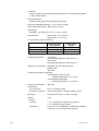
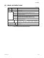
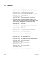
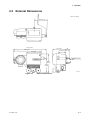
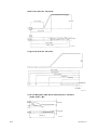
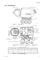
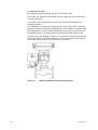
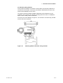
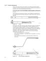
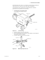
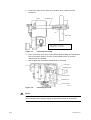
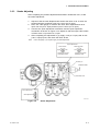
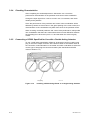
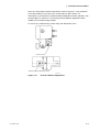
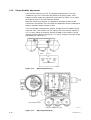
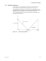
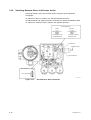
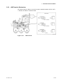
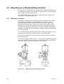
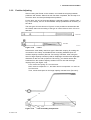
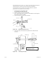
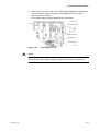
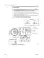
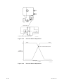
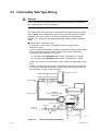
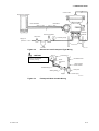
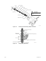
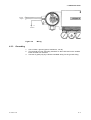
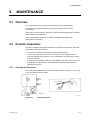
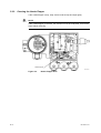
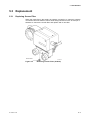
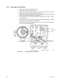
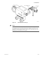
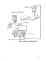
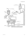
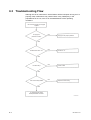
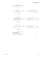
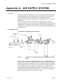
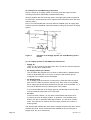
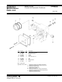
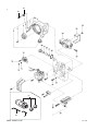
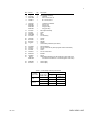
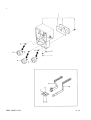
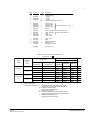

![User`s Manual VP200 電空ポジショナ [スタイル:S3]](http://vs1.manualzilla.com/store/data/006580025_2-2dfb5b0317a35a098ff3f5ae5358e081-150x150.png)