1
TS Series
TRUNKSAFE ® Fault Tolerant
Fieldbus System
October 2013
920222E
TS Series
TRUNKSAFE ® Fault Tolerant
Fieldbus System
Table of Contents
Introduction .............................................................................................................................................................................3
TRUNKSAFE System Configuration.......................................................................................................................................4
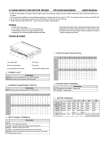
Specifications .........................................................................................................................................................................5
Dimensions .............................................................................................................................................................................6
Installation ..............................................................................................................................................................................9
TPS201-4 DIN Carrier Units ............................................................................................................................................9
TPS202 Advanced Power Conditioner ............................................................................................................................9
FDM252 Fieldbus Diagnostics Module ............................................................................................................................9
SPM201 Surge Protection Module ................................................................................................................................10
TS200 Series Device Couplers .....................................................................................................................................10
Terminal Designations ..........................................................................................................................................................11
Wiring Connections .......................................................................................................................................................12
Terminator .....................................................................................................................................................................12
Grounding .............................................................................................................................................................................13
Case Ground .................................................................................................................................................................13
Shield Ground ...............................................................................................................................................................13
Surge Ground ................................................................................................................................................................13
TS200 Device Coupler ..................................................................................................................................................13
Recommended Ground Wiring Practices .............................................................................................................................13
Troubleshooting ....................................................................................................................................................................14
LED Operation...............................................................................................................................................................14
CE Conformity ...............................................................................................................................................................15
Operation ..............................................................................................................................................................................15
Maintenance ..................................................................................................................................................................15
Customer Support ................................................................................................................................................................15
Control Drawings ..................................................................................................................................................................16
HOST Interface Kits ..............................................................................................................................................................18
Appendix A: TRUNKSAFE / Emerson DeltaV System Configuration ...................................................................................18
Appendix B: TRUNKSAFE / Yokogawa CENTUM System Configuration .............................................................................20
Appendix C: TRUNKSAFE / ABB System 800 Configuration ...............................................................................................21
Appendix D: TRUNKSAFE / Honeywell System Configuration .............................................................................................22
Appendix E: TRUNKSAFE / Invensys System Configuration ...............................................................................................23
Appendix F: TRUNKSAFE / Profibus System Configuration.................................................................................................24
Declaration of Conformity .....................................................................................................................................................25
Return and Warranty Procedures .........................................................................................................................................26
TS Series
TRUNKSAFE ® Fault Tolerant
Fieldbus System
Introduction
The TPS200 TRUNKSAFE Fault-Tolerant Fieldbus
System enables fault-tolerant FOUNDATION fieldbus
H1 and PROFIBUS PA segments. TRUNKSAFE
works with any Host configuration using a simplex
or redundant interface. A secure fieldbus physical
layer is made possible through the combination
of a Host Interface Kit, two redundant fieldbus DC
Power Conditioners and the specially engineered
TRUNKSAFE Device Coupler. This ensures that
TRUNKSAFE will maintain normal segment
communications even in the event of Host interface
failure1, power conditioner failure or an open- or shortcircuit of any cable between the Host Interface and the
field based device coupler.
TRUNKSAFE is FOUNDATION fieldbus ® registered
and fully compliant with FF831-1 (the technical
specification for fieldbus power supplies) and FF846-1
(the technical specification for device couplers).
TRUNKSAFE is fully compliant with IEC61158-2,
the fieldbus physical layer standard, and requires no
modifications to fieldbus devices or to Host software.
TRUNKSAFE System Configuration
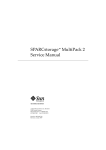
Figure 1 shows a TRUNKSAFE system configuration
and illustrates how TRUNKSAFE maintains continuous
segment communications between the Host and field
devices in the event of any single point failure, such as
an open or short circuit.
(Refer to Appendices for specific Host wiring
configurations. Contact MooreHawke if wiring
configurations for alternative Host systems are
required)
The TPS200 TRUNKSAFE Fault-tolerant Fieldbus
System is comprised of three main sections: Host
Interface, Power Conditioning, and a single field-based
device coupler
1
At time of this publication, PROFIBUS PA does not support
redundant interface cards.
The Host Interface, which is unique to each Host
vendor, provides two trunk outputs that will be carried
all the way to the device coupler in the field. Typically
this is done with redundancy adapters connected
to the Host interface (See Appendices). Additional
interface adapters (when needed) ensure that active
modules can be replaced without shutting down
communications. The resultant two trunk outputs
begin the redundant segment, and are then wired to
separate fieldbus power supply carrier boards. In most
cases this is accomplished with a plug-to-plug cable
connector carrying four segments.
Power conditioning is provided by the TRUNKSAFE
fieldbus power supply which comprises a DIN Carrier
(TPS201-4) populated with up to four Advanced
Power Conditioner Modules (TPS202), optional
surge protection (SPM201) and one Fieldbus
Diagnostics Module (FDM252). Each trunk is
connected to a separate carrier board (TPS201-4)
of the TRUNKSAFE fieldbus power supply. Each
carrier board supports four trunks with an individual
power conditioning module (TPS202) and a segment
terminator for each trunk.
A Fieldbus Diagnostics Module (FDM252) must be
fitted onto the DIN Carrier (one Module mounted per
Carrier) in order to provide alarm and diagnostics
information. It provides LED indicators for DC power
status, cable open- and short-circuits, noise on each
segment and a common contact closure (opens upon
alarm).
The optional Surge Protection Module, SPM201,
provides a full 3-element surge suppression circuit
per segment. The SPM201 fits directly onto the DIN
Carrier pluggable terminal socket (field-side) for the
segment being protected. This eliminates the need for
additional panel wiring or mounting space. A ground
connection for surge protection is provided through
a bus bar located within the DIN Carrier. Ground is
made externally available as a separate grounding
stud.
The single field-based device coupler receives power
and communications from each trunk. It can support
up to 6 (6 way) or 12 (12 way) devices. The TS200
Series device coupler is a specially engineered device
coupler with redundancy, automatic terminator, and
spur short circuit protection built into the coupler. In
addition, each coupler has led indicators for each
trunk, spur (normal and short circuit) and autoterminator.
3
TS Series
TRUNKSAFE ® Fault Tolerant
Fieldbus System
Figure 1. TRUNKSAFE System Configuration - Redundant operation
Available Host Interface Kits accommodate the
specific architectures of host specific configurations.
These provide a seamless connection to the
redundant physical H1 layer without affecting
host hardware or software. (See the TRUNKSAFE
User’s Manual for details.)
DCS
Redundant
H1 or PA
Interface
Moore
Industries
Host Interface
Kit
Two
Fieldbus
“Legs”
Trunk Cable B (less than 30m)
Termination
is NOT ACTIVE
+
S
Termination
is ACTIVE
Auto-detects system and
field cable failure and
then prevents
communications on
that side of the trunk
-
SPM201
Surge Protection
Module (optional)
Total cable length
per segment can be up to
1,900m (6,233ft), with a
maximum of 1,000m
(3,280ft) trunk on one side
+
Uninterrupted
Fieldbus Segment
Communications
Cable lengths on each
side do not need
to be balanced
TS206
TRUNKSAFE
Device Coupler
-
Up to 350mA of
isolated, redundant
and conditioned
power per segment
LED ON indicates
active trunk status
+ S
+ S
+ S
+ S
+ S
+ S
TRUNK
B
+ S
FF/PA
Devices
Field Enclosure
(optional)
Auto-Termination is ACTIVE
TRUNKSAFE’s Automatic Segment Termination
is initiated upon fault detection
on either side of the trunk
4
S
TPS202 Advanced
Power Conditioner Module
FDM252
On-board Diagnostics
Module provides
comprehensive fieldbus
physical layer diagnostics
+ S
BREAK!
T
TPS201-4
TRUNK
A
T
TPS201-4 Power
Conditioner DIN Carrier
Trunk Cable A (less than 30m)
TS Series
TRUNKSAFE ® Fault Tolerant
Fieldbus System
Specifications
Performance
Terminals
Performance
Indicators
TPS201-4 Power
Conditoner DIN Carrier
Number of Segments: 4
Supply Voltage: 19.2 to
32Vdc, reverse polarity
protected
Performance
LED Indicators
Type: Removable
terminals with screwclamp retaining screws
Wire Size: Handles
0.8-2.5mm2/12-24AWG
cable sizes
TPS202 Power
Conditioner Module
Output Capacity:
350mA per segment;
up to 25.5V (no load)
Power Requirements:
13.5VA @350mA per
segment
Power Dissipation:
5.5W @350mA per
segment
Terminator:
100 ohms/1microFarad
per segment
DC/DC Isolation:
500Vdc (segment to
power supply)
Alarm Relay
Output
FDM252 Fieldbus
Diagnostics Module
Power Dissipation:
0.5W maximum
Performance
LED Type: GREEN,
Normal; RED, Fault
LED A: DC “A” Input
Voltage Low (<18V)
LED B: DC “B” Input
Voltage Low (<18V)
LED 1: Segment #1
Noise High
(>75mV p/p)
LED 2: Segment #2
Noise High
(>75mV p/p)
LED 3: Segment #3
Noise High
(>75mV p/p)
LED 4: Segment #4
Noise High
(>75mV p/p)
Type: Relay (failsafe,
open on alarm)
Contact Rating:
5A@250Vac 50/60Hz
or 24Vdc, non-inductive
load
SPM201 Surge
Protection Module
Complies with:
-IEC 61158-2, for
31.25kB/s and testing
according to
-IEC 61643-21
Maximum Surge
Current Isn: 20kA
(8/20μsec)
Nominal Discharge
Current Isn:
3kA(8/20μsec)
Nominal Rated Current
In: 650mA
Maximum Continuous
OperatingVoltage
(MCOV): 35V
Peak Common Mode:
230V
Limiting Voltage Vlim:
50V@3kA (8/20μsec)
Nominal Voltage Vn: 32V
Line Attenuation: Rs: 1
ohm capacitance:1nF
IP Rating: IP20
Ambient
Conditions
(All TPS400
Components
and Options)
Operating Range:
–20°C to +60°C
(–4°F to +140°F)
Storage Range:
–40°C to +85°C
(–40°F to +185°F
Relative Humidity:
0-95%, non-condensing
RFI/EMI Immunity:
10V/m@80-1000MHz,
1kHz AM when tested
according to IEC61326
Cable Gland
(Device
Couplers with
Enclosures)
Type: Armored/
Unarmored
Material: Nickel-plated
brass
LED (Power): GREEN,
normal; ORANGE, Output
Voltage <18V
LED (Short): GREEN,
normal; RED, Cable Short
LED (Open): GREEN,
normal; RED, Cable Open
TRUNKSAFE Fieldbus Device Coupler (TS200)
Communications
FOUNDATION
Fieldbus™ H1 or
PROFIBUS PA
Performance
Maximum Quiescent
Current:
TS206: 13.5mA
TS20W: 25mA
Maximum Spur Output
Current: ISlim=48mA
Spur Short Circuit
Load: ISsc
2mA (typical)/6mA max.
Spur Voltage Drop:
0.5V@20mA spur
current (typical), 1V
maximum
Maximum Spur Voltage:
24V max. no load
LED
Indicators
Terminals
Enclosures
(Optional)
Trunk: GREEN (Active);
OFF (Inactive)
Spur: GREEN (Normal);
RED (Fault)
Auto-Terminator:
YELLOW (Terminator On);
OFF (Terminator Off)
Type: Removable
terminals with screwclamp retaining screws
Wire Size: Handles
sizes between
0.8-2.5mm2/12-24AWG
Type: Aluminum IP66;
Stainless Steel 316 IP66;
GRP (Glass Reinforced
Polyester) IP66
Ambient
Conditions
Operating Range:
–40°C to +70°C
(–40°F to +158°F)
Storage Range:
–40°C to +85°C
(–40°F to +185°F)
Relative Humidity:
0-95%, non-condensing
RFI/EMI Immunity:
10V/m@80-1000MHz,
1kHz AM when tested
according to IEC61326
5
TS Series
TRUNKSAFE ® Fault Tolerant
Fieldbus System
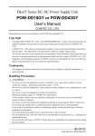
Dimensions
Figure 2. TPS201/202 Advanced Power Conditioner and Generic Redundancy Adapter with DIN-Rail Mounting Installation Dimensions
216mm
(8.50 in)
TOP VIEW
TPS200
114mm
(4.50 in)
121mm
(4.77 in)
SIDE VIEW
(Shown with SPM
Surge Protection
Module Installed)
57mm
(2.23 in)
70mm
(2.74 in)
FRONT VIEW
114mm
(4.50 in)
6
TS Series
TRUNKSAFE ® Fault Tolerant
Fieldbus System
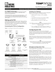
Figure 3-A. TS200 Device Coupler DIN-Rail Mounting Installation Dimensions (Base Unit)
127mm
(5.00 in)
6-Spur (Shown)
204mm
(8.05 in)
12-Spur
TOP VIEW
SIDE VIEW
51mm
(1.99 in)
82mm
(3.23 in)
Figure 3-B. DIN-Rail Mounting Installation Dimensions with Optional ATEX barrier
127mm
(5.00 in)
6-Spur
204mm
(8.05 in)
12-Spur
73mm
(2.90 in)
51mm
(1.99 in)
82mm
(3.23 in)
TOP VIEW
SIDE VIEW
7
TS Series
TRUNKSAFE ® Fault Tolerant
Fieldbus System
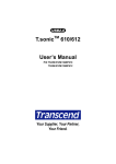
Figure 4. Standard Aluminum Enclosure Installation Dimensions for 6-Spur (TS256) and 12-Spur (TS25W) Models
175mm
(6.89 in)
322mm
(12.68 in)
156mm
(6.14 in)
274mm
(10.79 in)
293mm
(11.54 in)
367mm
(14.45 in)
107mm
(4.21 in)
GROUND STUD
SCREW
#10-32
DIA. 4.8mm
(0.190 in)
8
TS Series
TRUNKSAFE ® Fault Tolerant
Fieldbus System
Figure 5. Stainless Steel 316 with E-Z Vertically Removable Lid and Bottom Entry Cable Gland Plate 12-Spur Models (TS24W)
319mm
(12.56 in)
Model No :
Serial No :
Tag No :
TRUNKGUARD
Series 200 Device Coupler
Moore Industries-International North Hills CA, USA
MIN
CLEARANCE
FOR PLASTIC ENCLOSURES:
CLEAN ONLY WITH DAMP CLOTH
35mm (1.50 in)
260mm
(10.24 in)
Padlock fixing
GROUND STUD
M10
183mm
(7.20 in)
224mm
(8.82 in)
248mm
(9.76 in)
REMOVABLE GLAND PLATE
135mm x 175mm
(5.31 in x 6.89 in)
PRE-DRILLED
M20 ENTRIES 2x PLATES
Model No :
Serial No :
Tag No :
TRUNKSAFE
Series 200 Device Coupler
Moore Industries-International North Hills CA, USA
FOR PLASTIC ENCLOSURES:
CLEAN ONLY WITH DAMP CLOTH
Figure 6. GRP (Glass Reinforced Polyester) Enclosure Installation Dimensions for 6-Spur (TS236) Models
244mm
(9.60 in)
260mm
(10.24 in
Shown with
Unarmored
Cable Glands
140mm
(5.51 in)
105mm
(4.13 in)
160mm
(6.30 in)
55mm
(2.17 in)
9
TS Series
TRUNKSAFE ® Fault Tolerant
Fieldbus System
Installation
TPS201-4 DIN Carrier Units
DIN Carrier Units fit onto 32mm (EN50035) G-type
and 35mm (EN50022) Top Hat DIN-rails. They should
be mounted in a way to allow easy access to terminal
receptacles and to keep LEDs visible. Horizontal
DIN-rails are preferred so that air can flow vertically
between the Conditioners to assist in module cooling.
An outdoor location requires an external enclosure.
Any enclosure meeting the requirements of the
location in relation to electrical and mechanical safety
can be used (a minimum of IP54 is recommended).
Contact MooreHawke for specific advice regarding
installation of TPS201 DIN Carriers in any hazardous
area.
TPS202 Advanced Power Conditioner
Resistors
Additionally, since the TPS202 continually monitors
for open or short connections, if a TPS202 module is
installed on the Carrier and is not being used in the
system, the resistors provided (3.3kohm, 1W) in the
TRUNKSAFE Kit, P/N: 208-265-00, must be placed on
the Field and Host sides (at the + and – terminals not
required on the Host side if DB25 cable is used and
Interface/ Redundant adapter is connected) of that
segment to prevent the Fieldbus Diagnostics Module
from alarming. Resistors must be removed when the
Trunk cables and Host wiring is added.
Resistors must also be placed on the field and Host
side terminals for bench test purposes.
Figure 7. Example of Jumper and Resistor Placement
Advanced Power Conditioners fit onto sockets on the
Carrier face. They only mount in one orientation and
should be secured to the Carrier using the on-board
screws. For shipping purposes, a jumper is fitted
to each socket. It must be removed prior to module
installation. Should a Power Conditioner be removed,
the Fieldbus Diagnostics Module will indicate an
alarm.
FDM252 Fieldbus Diagnostics Module
FDM252 Alarms
There are multiple reasons that a Fieldbus Diagnostics
Module may alarm. See Testing and Trouble Shooting
Section of this Manual for details. These include an
error within your system.
Jumpers
The TPS201 Carrier Module is shipped with jumpers
fitted into the appropriate unused power slots (as
marked). These jumpers must be placed (or retained)
in any unused slot once the Carrier is used in an
application, or else the alarm will be set on the
Fieldbus Diagnostics Module. Extra jumpers are
supplied in the TRUNKSAFE Kit, P/N: 208-265-00.
10
+
S
-
Fieldbus Diagnostics Modules fit onto sockets on
the Carrier face. They only mount in one orientation.
Use the on-board screws to secure the module to the
Carrier.
TS Series
TRUNKSAFE ® Fault Tolerant
Fieldbus System
SPM201 Surge Protection Module
Surge Protection Modules (optional component)
fit onto the field-side pluggable socket on the DIN
Carrier face and accept the field-side pluggable
terminals. They only mount in one orientation. A long
screw is provided to secure the unit to the Carrier.
This replaces the screw that is used to fasten the
Advanced Power Conditioner modules to the Carrier
face. It must be fitted in order to complete the ground
connection of the Surge Protection Module.
TS200 Series Device Couplers
Device Couplers are typically located in the field. The
TS200-DIN is supplied by MooreHawke for installation
within a user-selected protective enclosure. Fieldmounting enclosures along with cable glands/sockets
can be ordered through MooreHawke. Refer to the
TS Series data sheet for available enclosures.
Device Coupler location should be selected in order to
allow easy access for field wiring but also to provide
protection from mechanical damage or product
spillage.
TS200 Series Device Couplers with MooreHawkesupplied external enclosures should be mounted to
vertical surfaces in an orientation that prevents cable
entry from above. Cables connected to all external
enclosures should be oriented to prevent water
running down the cable and into the enclosure entry.
Cables approaching from above should continue down
past the Device Coupler for at least 250mm (10 in),
and then return upwards to the cable entry. Cables
should be externally supported within 250mm (10 in)
of the cable entry itself, particularly if armored cable
is used. All unused cable entries should be sealed
(MooreHawke-supplied enclosures with cable glands
incorporate IP66 seals on all entries as standard).
Installation in third-party enclosures (not supplied by
MooreHawke) and in hazardous locations should meet
the requirements and appropriate approvals of that
particular location.
Please refer to TS200 ATEX and IECEx Certification
section for more details.
The Device Coupler should be secured to a DIN-rail
and protected from external factors with an enclosure
meeting a minimum of IP54 and that adheres to the
following:
1. The enclosure must be compliant with the
requirements for Directive 94/9/EC, Category 3 G
applications.
2. A minimum clearance of 1mm must be maintained
between live parts and grounded metal.
3. If other electrical circuits are fitted into the
enclosure, they must be approved for the hazardous
area. See Control Drawing 100-100-79 for further
enclosure requirements.
11
TS Series
TRUNKSAFE ® Fault Tolerant
Fieldbus System
Terminal Designations
TPS200
TS206 6-way shown below or TS20W 12-way
12
TS Series
TRUNKSAFE ® Fault Tolerant
Fieldbus System
Wiring Connections
Each segment requires two independent field cables
(typically called Trunk A and Trunk B). For maximum
availability, each should have separate routing through
the field until they meet at the TS200 Device Coupler.
There is no need to balance the length of these two
components, but the total length of all cables in any
segment cannot exceed 1900m.
Any cable suitable for FOUNDATION fieldbus /
PROFIBUS PA applications may be used. This is
typically 18-22 AWG (0.8-1.5mm2 cross-sectional
area) cable with individual shields (normally called
Type A cable). Components from multiple segments
may be combined within a multi-core cable. If used, a
separate multi-core shielded cable is required for both
Trunk A and Trunk B cables. This is recommended
in order to maintain separation of wiring. It is also
recommended that various component shields remain
independant of each other within the multi-core cable.
Wire terminations should be made from cables
stripped to expose no more than 8mm (0.3 in)
of conductor and inserted fully into the terminal
opening. Bootlace ferrules are recommended for use
with stranded cable. Field-side segment wiring is
made via screw-clamp pluggable terminals marked
FIELD. HOST connections are made either through
the terminals marked HOST or via multi-way cables
plugged directly to the header on the TPS201-4
Carrier board.
Nominal 24Vdc (19.2-32Vdc) power is required for
terminals marked DC Power. Provisions are made for
two independent DC feeds to the Carrier.
Note:
If only one DC power feed is to be used, a pair
of jumper wires is required to the second set
of DC feed terminals to ensure that the alarm
monitoring circuit within the FDM252 (optional
component) operates correctly.
At the TS200 Series Device Coupler, Trunk A and
Trunk B are brought together and each Trunk is
connected to one of the Trunk IN ports. The TS200
Series Device Coupler has a number of spur ports for
the connection of field devices, depending on model.
Wire terminations from field devices, including shield/
screen wiring, should be made (as described above)
into the appropriate screw-clamp pluggable terminal.
Only one field device should be connected per spur.
WARNING:
For -ATEX units used in Zone 2 applications: Only
the pluggable connectors supplied with the unit can
be used for spur connections. This ensures that
spurs cannot be plugged into the trunk sockets.
Caution:
It is recommended that the shield from field devices
NOT be connected to the field device case.
Once all wiring connections have been made, all
retaining screws on each module should be securely
fastened and any external enclosure closed (where
applicable).
Terminator
In the TRUNKSAFE system, each trunk is terminated
by a 100 ohm resistor in series with a 1uF capacitor,
hard-wired at each Advanced Power Conditioner
position. No terminator is required at the HOST H1
interface.Contact MooreHawke if the HOST link cable
is in excess of 30m (100ft).
In normal operation the segment is “terminated” at
each of the power conditioners. The terminator in the
field based device coupler is only activated in the
event of a fault (i.e., cable break, short, etc).
13
TS Series
TRUNKSAFE ® Fault Tolerant
Fieldbus System
Grounding
The TPS200 carrier is provided with three independent
connection points relating to ground. This section
provides details of each connection point and provides
recommendations on connecting these grounds.
Recommended Ground Wiring
Practices
Moore Industries recommends the following ground
wiring practices:
s
Any MooreHawke product in a metal case or
housing should be grounded.
s
The protective earth conductor must be
connected to a system safety earth ground
before making any other connections.
s
The maximum length of unshielded input and
output signal wiring should be 2 inches.
s
Some local electrical codes or facility practices
may require the Shield to be connected to
Ground at more than one location. Follow proper
local guidelines.
Case Ground
The CASE ground connection is for personnel
protection and should be connected to the local
structural ground in the panel or enclosure, typically
the incoming ac power ground, if available. The case
can also be grounded via the DIN rail.
Shield Ground
The SHIELD ground is the collection point for all of
the shields relating to the fieldbus signals (both fieldand HOST-side). This may be directly connected to
ground, through a capacitor or via the HOST ground.
Note:
If capacitor is not used, only one SHIELD
ground is needed either at the power carrier
or at the HOST top end. However, if it is at the
power carrier, then connect SHIELD point to
GROUND.
Surge Ground
The SURGE ground is available for those installations
that use the SPM201 surge protection modules.
These are designed to divert very large/short duration
currents associated with surges (up to 20kA) and so
these should not be connected to the normal SHIELD
ground. When used for surge protection, the shorting
bar between these ground points must be removed.
Therefore, if no surge protection is being used, this
shorting bar must be always connected to ground.
TS200 device coupler
The device coupler case should be grounded via the
DIN rail.
14
Fieldbus cable shields are “carried through” the
Carrier’s input/output terminals and require a suitable,
noise-free ground connection point. The selected
point is generally the HOST power or I/O ground rail.
If SPM201 Surge Protection Units are fitted, their
securing screw must be installed per unit and the
TPS201-4 DIN Carrier must be connected to a low
impedance surge protection ground with a direct cable
of at least 10 AWG (10mm2 cross-sectional area) from
the grounding lug provided.
TS Series
TRUNKSAFE ® Fault Tolerant
Fieldbus System
CE Conformity
Installation of any Moore Industries’ products that
carry CE certification (Commission Electrotechnique)
must adhere to the guidelines in Recommended
Ground Wiring Practices in order to meet
the requirements set forth in applicable EMC
(Electromagnetic Compatibility) directives 2004/108/
EC, EN 61326. Consult the factory for the most
current information on products that have been CE
certified.
Figure 8. Grounding options
Surge Ground
Shield Ground
Case Ground
Shorting Bar
15
TS Series
TRUNKSAFE ® Fault Tolerant
Fieldbus System
Testing and Troubleshooting
Figure 9. Module LED Indicators
Refer to Table 1 for information on LED indications of
fault conditions.
TPS202
If the HOST cables are not connected to the HOST,
or if Advanced Power Conditioners are installed and
powered but with no device coupler connected, the
Fieldbus Diagnostics Module will display a constant
alarm. This alarm can be suppressed by installing
load resistors (3.3kohm, 1W) into the pluggable
terminals during commissioning.
FDM252
Note that the DIN Carrier has a link fitted at each
Power Conditioner position. The link must be removed
prior to installation and must be replaced should a
Power Conditioner be removed.
LED Operation
During normal operation, LED sequence should be as
follows:
TPS202 Advanced Power Conditioners: All LEDs
should be GREEN.
Table 1. Troubleshooting
TPS202 Advanced Power Conditioner
LED
LED Indication
POWER
OUT LOW
GREEN
Amber
OFF
Normal Operation
Output Voltage < 18V
Module failure
GREEN
RED
OFF
Normal Operation
Cable short-circuit
Module failure
GREEN
RED
OFF
Normal Operation
Cable open-circuit
Module failure
SHORT CIRCUIT
Note:
An open-circuit on the TPS202 can occur on the
HOST or the field side of the segment. To determine
which side is open, measure the voltage on the
FIELD side connector. If the measured voltage
is null, then the open circuit is on the field side.
Alternatively, if voltage is present, then the open
circuit is on the HOST side.
FDM252 Diagnostics Modules: All LEDs should be
GREEN.
OPEN CIRCUIT
FDM252 Fieldbus Diagnostic Module
LED
DC01
DC02
NOISE 1
NOISE 2
TS200 Series Device Coupler: All Spur LEDs should
be GREEN.
If any RED LED is ON, or any GREEN LED is OFF,
refer to Table 1 for troubleshooting tips.
NOISE 3
NOISE 4
LED Indication
GREEN
RED
OFF
Normal Operation
Input Voltage 1 < 18V
Module failure
GREEN
RED
OFF
Normal Operation
Input Voltage 2 < 18V
Module failure
GREEN
RED
OFF
Normal Operation
Noise > 75mVp/p
Module failure
GREEN
RED
OFF
Normal Operation
Noise > 75mVp/p
Module failure
GREEN
RED
OFF
Normal Operation
Noise > 75mVp/p
Module failure
GREEN
RED
OFF
Normal Operation
Noise > 75mVp/p
Module failure
TS200-DIN Fieldbus Device Coupler
In normal operation the Auto Terminator led will be off.
It will only be on (YELLOW) if there is a Trunk failure
(i.e., cable break, short, etc).
LED
LED Indication
GREEN
Trunk A
Trunk B
Normal Operation
GREEN
N/A
N/A
Normal Operation
*Spur
Auto Terminator
**Loss of Power
OFF
**Loss of Power
GREEN
RED
OFF
Normal Operation
Spur short-circuit
**Loss of Power
YELLOW
N/A
Terminator ON
*Spur has two LEDs to indicate normal and fault conditions.
**Cable open- or short-circuit is due to loss of power.
16
OFF
OFF
Terminator OFF
TS Series
TRUNKSAFE ® Fault Tolerant
Fieldbus System
TS200 ATEX and IECEx Certification
Operation
Special Conditions of Certification
Once configured, installed and supplied with the
correct power, TRUNKSAFE begins to operate
immediately.
The Model TS206 and Model TS2W Device Couplers
shall be powered by the Moore Industries Model
TP202 Power Supply.
When the TS200 device coupler is installed as
Category 3 equipment, it shall be installed in an
enclosure which maintains an ingress protection
rating of IP54 and meets the enclosure requirements
of EN60079-0 and EN60079-15 (IEC 60079-0 and
IEC60079-15 for IECEx).
ATEX Zone 2 only:
Legacy systems installed prior to May 1st, 2013 may
install replacement TS200 units with energy limited
spurs using installation diagram on page 2 of
100-100-76.
All new ATEX Zone 2 installations or system
expansions after May 1st 2013 must use intrinsically
safe wiring for spur circuits per installation diagram
100-100-79.
Maintenance
Moore Industries suggests a quick check for terminal
tightness and general unit condition every 6-8
months. Always adhere to any site requirements for
programmed maintenance.
TPS200 Series modules contain no user-serviceable
parts. Non-functioning units under warranty should be
returned to Moore Industries for replacement or repair.
Due to the nature of materials used to manufacture
the TPS200 Series Power Conditioners and TS200
Series Device Couplers the user/installer should
exercise caution with regard to possible attack by
aggressive substances in any specific installation.
Customer Support
If service assistance is ever required for an device in
your application, refer to the back cover of this manual
for the telephone numbers to Moore Industries’
customer service department.
If possible, make a note of the model number of the
unit before calling. For fastest assistance, have the
following information available: serial number, the job
number and purchase order number under which it
was shipped.
17
TS Series
TRUNKSAFE ® Fault Tolerant
Fieldbus System
HOST Interface Kits
The table below shows the interface adapters,
redundant adapters, and cables needed for installation
for your specific system. Refer to appendices for
examples of system configurations.
Table. Moore Industries Interface options
Generic (ABB, SMAR,
Rockwell, Honeywell)
Emerson
Invensys
Yokogawa
Kit
Number
804-905-27
804-906-27
804-907-27
804-904-27
804-908-27
Cable
(from Carrier
to Interface
Adapter)
Not required
2 x 804-011-26
804-009-26
2 x 804-009-26
804-013-26*
2 x 804-009-26
Interface
Adapter
Not required
2 x 804-866-27
2 x 804-867-27
2 x 804-867-27
2 x 804-867-27
804-869-27
804-861-27
804-868-27
Redundant
Adapter
2 x 804-858-27
804-864-27
Profibus
* Use with Honeywell with alarm connections from Redundant Adapter to H1 Card.
21
TS Series
TRUNKSAFE ® Fault Tolerant
Fieldbus System
The redundant adaptor fits directly onto the Emerson
Redundant Carrier terminals and makes independent
terminals available for both redundant segments:
Trunk1_1A, Trunk1_1B, Trunk 1_2A and Trunk 1_2B
(refer to Figure A-2). This allows each trunk to be
connected to the selected pair of TPS202 Advanced
Power Conditioners, which may be on the same, or
separate, TPS201-4 DIN Carriers, as required. Refer
to Figure A-1 for an example of splitter operation.
Appendix A: TRUNKSAFE/
Emerson DeltaV System
Configuration
DeltaV is a digital automation system from Emerson
Process Management. DeltaV incorporates
FOUNDATION Fieldbus I/O capability via H1 cards.
Redundant H1 cards are supported if using a DeltaV
Series 6.0 or later which utilizes Series 2 H1 cards.
To install TRUNKSAFE with an Emerson DeltaV
system, refer to Figure A-1 below.
TRUNKSAFE can also be connected with the same
HOST Interface Kit to the new S-Series H1 I/O cards
(provided they do not have integrated power).
Figure A-1. TRUNKSAFE / Emerson DeltaV System Configuration
Emerson
Redundant
Carrier
Series 2
H1 Card
H1 Card
CH2
-VE
-VE
CH1
CH2
H1 CARD
MOORE IND. INT’L U.S.A.
P/N 804-858-27A
CH2
-VE
11 12 13 14
+VE
6
+VE
5
-VE
+VE
4
+VE
3
Redundant Adapters
Moore Industries
P/N: 804-858-27*
-VE
s
s
CH1
H1 CARD
MOORE IND. INT’L U.S.A.
P/N 804-858-27A
CH1
-VE
+VE
+VE
CARRIER
s
s
CH2
-VE
s
s
CH1
-VE
+VE
CARRIER
+VE
s
s
* This configuration supports
2 segments (1 Emerson
H1 Interface); for a 4 segment
configuration an additional HOST
Interface Kit is required.
Segment
2_1B
Segment
2_1A
Segment
1_1A
Segment
1_1B
TPS202
TPS202
TPS201-4
TPS201-4
TPS200
TPS200
FDM252
SPM201
Surge Protection
Module (optional)
FDM252
SPM201
Surge Protection
Module (optional)
Trunk #4_1A
Trunk #4_1B
Trunk #3_1B
Trunk #3_1A
Trunk #2_1B
Trunk #2_1A
–
+
+ S
+ S
–
–
+ S
+ S
Trunk
#1_1A
+ S
+ S
+
+
TRUNK
A
TS206
22
TRUNK
B
+ S
+ S
Trunk
#1_1B
TS Series
TRUNKSAFE ® Fault Tolerant
Fieldbus System
Moore Industries supplied DB25 cables, P/N 804-00926. The standard length of the DB25 cables is six feet.
Longer cable lengths can be provided upon special
request. The maximum allowable length of each DB25
cable connection is 30 meters (~100 feet).
Appendix B: TRUNKSAFE /
Yokogawa CENTUM System
Configuration
Yokogawa CENTUM Systems can be connected
using the 804-869-27 Redundancy Adapter.
The connections between the ALF111 and the
Redundancy Adapter are completed with the
Yokogawa supplied AKB336 cables. The connections
between the Redundancy Adapter and the
TRUNKSAFE TPS201-4 are completed with
One DB25 (804-009-26) cable carries four segments
from one ALF111 (1A, 2A, 3A, 4A) and the other
DB25 (804-009-26) cable carries the other side
of the redundant pair (1B, 2B, 3B, 4B) from the
standby ALF111. Two TPS201-4 DIN Carriers then
automatically support the 4 pairs of segment trunk
cables. Refer to Figure A-2 for system confi guration.
Figure A-2. TRUNKSAFE / Yokogawa CENTUM System Configuration
PRM
HIS
V net
FCS
FCU
ESB bus
ALF111 ALF111
SERVICE SERVICE
AKB336
AKB336
Interface Adapters
MooreHawke
P/N: 804-867-27
Carrier
GENERIC
Redundant Adapter
for Yokogawa
MooreHawke
P/N: 804-869-27
Side View
804-009-26
804-009-26
TPS202
TPS202
TPS201-4
TPS201-4
TPS200
TPS200
FDM252
SPM201
Surge Protection
Module (optional)
FDM252
SPM201
Surge Protection
Module (optional)
Trunk #4_A
Trunk #4_B
Trunk #3_B
Trunk #3_A
Trunk #2_A
–
–
–
+ S
+ S
TRUNK
A
TS206
+
+ S
+ S
Trunk
#1_A
+ S
+ S
+
Trunk #2_B
Trunk
#1_B
+
TRUNK
B
+ S
+ S
23
TS Series
TRUNKSAFE ® Fault Tolerant
Fieldbus System
Appendix C: TRUNKSAFE/
ABB System 800 Configuration
redundant adapter. Then connect the TPS201-4 to
redundant adapter using 804-009-26 cable one per
TRUNKSAFE unit.
TRUNKSAFE can be wired to each channel at the
LD 800HSE linking device using 804-861-27
Refer to Figure A-3 for installation instructions.
Figure A-3. TRUNKSAFE / ABB System 800 Configuration
Server
Server
Control Network
Top View
1
AC 800M
2
3
4
- s + - s + - s + - s +
AC 800M
REDUNDANCY
HSE Subnet
LD 800HSE
Interface Adapters
MooreHawke
P/N: 804-867-27
LD 800HSE
1
2
P
F
1
2
R
3
4
HSE
R
3
4
HSE
HSE
COM
F
COM
P
HSE
LD 800HSE
LD 800HSE
Connection
Redundant Adapter
MooreHawke
P/N: 804-861-27
TPS202
TPS202
804-009-26
804-009-26
TPS201-4
TPS201-4
TPS200
TPS200
FDM252
FDM252
Trunk #4_A
SPM201
Trunk #3_A
Trunk #4_B
SPM201
Trunk #3_B
Trunk #2_A
Trunk #2_B
Trunk In
Trunk In
+ S
+ S
TRUNK
B
TRUNK
A
+ S
+ S
+ S
+ S
+ S
+ S
TS206
24
TS Series
TRUNKSAFE ® Fault Tolerant
Fieldbus System
Appendix D: TRUNKSAFE/
Honeywell System
Configuration
To utilize TRUNKSAFE with a Honeywell system, refer
to Figure A-4 below.
Honeywell
Series ‘C’ FIM
Figure A-4. TRUNKGUARD / Honeywell System Configuration
Top View
Redundant Adapter
Moore Industries
P/N: 804-861-27
1
2
3
4
- s + - s + - s + - s +
REDUNDANCY
1
Interface Adapters
MooreHawke
P/N: 804-867-27
2
3
4
Either cable
method wiring
can be
used.
804-013-26
Segments 1 - 4
(Multi-Segments with alarm connections)
TPS202 Power Conditioner
TPS202
804-009-26
804-009-26
TPS201-4
TPS201-4
TPS200
TPS200
FDM252
FDM252
Trunk #4_A
Trunk #3_A
SPM201
Trunk #3_B
Trunk #2_A
Trunk #2_B
Trunk In
Trunk In
+ S
+ S
TRUNK
B
TRUNK
A
+ S
+ S
+ S
+ S
+ S
+ S
SPM201
Surge Arrestor
Trunk #4_B
TS206
25
TS Series
TRUNKSAFE ® Fault Tolerant
Fieldbus System
The Redundant adapter mounts directly on the I/A
System carrier board. The interface adapters mount
on the redundancy adapter and can be independently
removed during operation. The interface adapter circuit
is comprised of a passive diode network and series
capacitors.
Appendix E: TRUNKSAFE/
Invensys System Configuration
To utilize TRUNKSAFE with a Invensys system, refer
to Figure A-5 below.
Figure A-5. TRUNKGUARD / Invensys System Configuration
Invensys
Interface Adapters
Moore Industries
P/N: 804-866-27
Carrier
Redundant Adapter
Moore Industries
P/N: 804-864-27
TPS202 Power Conditioner
TPS202
804-009-26
804-009-26
TPS201-4
TPS201-4
TPS200
TPS200
FDM252
FDM252
Trunk #4_A
SPM201
Surge Arrestor
Trunk #3_A
Trunk #4_B
SPM201
Trunk #3_B
Trunk #2_A
Trunk #2_B
Trunk In
Trunk In
+ S
+ S
TRUNK
B
TRUNK
A
+ S
+ S
+ S
+ S
+ S
+ S
TS206
26
TS Series
TRUNKSAFE ® Fault Tolerant
Fieldbus System
Appendix F: TRUNKSAFE/
Profibus PA or any Host with
non-redundant H1 Cards
To utilize TRUNKSAFE with a Profibus system, refer to
Figure A-6 below.
Server
Figure A-6. TRUNKSAFE/ Profibus System Configuration
Control Network
Top View
DP/PA
Coupler
or
HI Segment
1
2
3
Redundant Adapter
Moore Industries
P/N: 804-861-27 or 804-868-27
4
- s + - s + - s + - s +
REDUNDANCY
Interface Adapters
MooreHawke
P/N: 804-867-27
TPS202
Power Conditioner
804-009-26
TPS202
804-009-26
TPS201-4
TPS201-4
TPS200
TPS200
FDM252
FDM252
Trunk #4_A
Trunk #3_A
SPM201
Trunk #3_B
Trunk #2_A
Trunk #2_B
Trunk In
Trunk In
+ S
+ S
TRUNK
B
TRUNK
A
+ S
+ S
+ S
+ S
+ S
+ S
SPM201
Surge Arrestor
Trunk #4_B
TS206
27
EC Declaration of Conformity
Moore Industries-International, Inc.
16650 Schoenborn Street
North Hills, CA 91343-6196 U.S.A.
Date Issued: 26 Sept. 2013
No. 100-100-236 Rev. A
Page 1 of 1
Equipment Description:
TRUNKSAFE Series Fieldbus Device Coupler
Model TS2 / * / * / * / * / -ATEX
* Indicates enclosure, spurs, gland type, gland size and options as stated in the product data sheet.
Directive:
2004/108/EC (EMC: Electromagnetic Compatibility)
Specifications Conformed To:
EN 61326-1:2006 Electrical equipment for measurement, control and laboratory use - EMC requirements
Equipment Description:
TRUNKSAFE Series Fieldbus Device Coupler
Model TS2 / * / * / * / * / -ATEX
* Indicates enclosure, spurs, gland type, gland size and options as stated in the product data sheet.
Directive:
94/9/EC (ATEX: Equipment and protective systems for potentially explosive atmospheres)
Provisions of the Directive Fulfilled by the Equipment:
Group II Category 3 G Ex nA nC [ic] IIC T4 (Ta -40ÛC to +70ÛC)
Technical File No.: TS200-TF001
Conformity Assessment Procedure:
Internal Control of Production - Annex VIII (Module A)
Technical Standards Referenced:
EN 60079-0:2009 Explosive atmospheres Part 0: Equipment - General requirements
EN 60079-11:2012 Explosive atmospheres Part 11: Equipment protection by intrinsic safety ”i”
EN 60079-15:2011 Explosive atmospheres Part 15: Equipment protection by type of protection ”n”
On Behalf of Moore Industries-International, Inc., I declare that, on the date the equipment accompanied by this
declaration is placed on the market, the equipment conforms with all technical and regulatory requirements of
the above listed directives.
Signature:
Deanna Esterwold, Quality Manager
EC Declaration of Conformity
Moore Industries-International, Inc.
16650 Schoenborn Street
North Hills, CA 91343-6196 U.S.A.
Date Issued: 03 Oct. 2013
No. 100-100-237 Rev. A
Page 1 of 1
Equipment Description:
TRUNKSAFE Series Fieldbus Device Coupler
Model TS2 / * / * / * / * / *
* Indicates enclosure, spurs, gland type, gland size and options as stated in the product data sheet.
Directive:
2004/108/EC (EMC: Electromagnetic Compatibility)
Specifications Conformed To:
EN 61326-1:2006 Electrical equipment for measurement, control and laboratory use - EMC requirements
Equipment Description:
TRUNKSAFE Series Fieldbus Device Coupler
Model TS2 / * / * / * / * / *
* Indicates enclosure, spurs, gland type, gland size and options as stated in the product data sheet.
Directive:
94/9/EC (ATEX: Equipment and protective systems for potentially explosive atmospheres)
Provisions of the Directive Fulfilled by the Equipment:
Group II Category 3 G Ex nA nC [nL] IIC T4 (Ta -40ÛC to +70ÛC)
Type Examination Certificate:
FM 08 ATEX 0050 X
Technical Standards Referenced:
EN 60079-0:2006 Explosive atmospheres Part 0: Equipment - General requirements
EN 60079-15:2005 Explosive atmospheres Part 15: Equipment protection by type of protection ”n”
On Behalf of Moore Industries-International, Inc., I declare that, on the date the equipment accompanied by this
declaration is placed on the market, the equipment conforms with all technical and regulatory requirements of
the above listed directives.
Signature:
Deanna Esterwold, Quality Manager
RETURN PROCEDURES
To return equipment to Moore Industries for repair, follow these four steps:
1. Call Moore Industries and request a Returned Material Authorization (RMA) number.
Warranty Repair –
If you are unsure if your unit is still under warranty, we can use the unit’s serial number
to verify the warranty status for you over the phone. Be sure to include the RMA
number on all documentation.
Non-Warranty Repair –
If your unit is out of warranty, be prepared to give us a Purchase Order number when
you call. In most cases, we will be able to quote you the repair costs at that time.
The repair price you are quoted will be a “Not To Exceed” price, which means that the
actual repair costs may be less than the quote. Be sure to include the RMA number
on all documentation.
2. Provide us with the following documentation:
a) A note listing the symptoms that indicate the unit needs repair
b) Complete shipping information for return of the equipment after repair
c) The name and phone number of the person to contact if questions arise at the factory
3. Use sufficient packing material and carefully pack the equipment in a sturdy shipping container.
4. Ship the equipment to the Moore Industries location nearest you.
The returned equipment will be inspected and tested at the factory. A Moore Industries representative will contact the person designated on your documentation if more information is
needed. The repaired equipment, or its replacement, will be returned to you in accordance
with the shipping instructions furnished in your documentation.
WARRANTY DISCLAIMER
THE COMPANY MAKES NO EXPRESS, IMPLIED OR STATUTORY WARRANTIES (INCLUDING ANY WARRANTY OF MERCHANTABILITY OR
OF FITNESS FOR A PARTICULAR PURPOSE) WITH RESPECT TO ANY
GOODS OR SERVICES SOLD BY THE COMPANY. THE COMPANY DISCLAIMS ALL WARRANTIES ARISING FROM ANY COURSE OF DEALING
OR TRADE USAGE, AND ANY BUYER OF GOODS OR SERVICES FROM
THE COMPANY ACKNOWLEDGES THAT THERE ARE NO WARRANTIES
IMPLIED BY CUSTOM OR USAGE IN THE TRADE OF THE BUYER AND
OF THE COMPANY, AND THAT ANY PRIOR DEALINGS OF THE BUYER
WITH THE COMPANY DO NOT IMPLY THAT THE COMPANY WARRANTS
THE GOODS OR SERVICES IN ANY WAY.
ANY BUYER OF GOODS OR SERVICES FROM THE COMPANY
AGREES WITH THE COMPANY THAT THE SOLE AND EXCLUSIVE REMEDIES FOR BREACH OF ANY WARRANTY CONCERNING THE GOODS OR
SERVICES SHALL BE FOR THE COMPANY, AT ITS OPTION, TO REPAIR
OR REPLACE THE GOODS OR SERVICES OR REFUND THE PURCHASE
PRICE. THE COMPANY SHALL IN NO EVENT BE LIABLE FOR ANY CONSEQUENTIAL OR INCIDENTAL DAMAGES EVEN IF THE COMPANY FAILS
IN ANY ATTEMPT TO REMEDY DEFECTS IN THE GOODS OR SERVICES
, BUT IN SUCH CASE THE BUYER SHALL BE ENTITLED TO NO MORE
THAN A REFUND OF ALL MONIES PAID TO THE COMPANY BY THE BUYER
FOR PURCHASE OF THE GOODS OR SERVICES.
ANY CAUSE OF ACTION FOR BREACH OF ANY WARRANTY BY
THE COMPANY SHALL BE BARRED UNLESS THE COMPANY RECEIVES FROM THE BUYER A WRITTEN NOTICE OF THE ALLEGED
DEFECT OR BREACH WITHIN TEN DAYS FROM THE EARLIEST DATE
ON WHICH THE BUYER COULD REASONABLY HAVE DISCOVERED
THE ALLEGED DEFECT OR BREACH, AND NO ACTION FOR THE
BREACH OF ANY WARRANTY SHALL BE COMMENCED BY THE
BUYER ANY LATER THAN TWELVE MONTHS FROM THE EARLIEST
DATE ON WHICH THE BUYER COULD REASONABLY HAVE DISCOVERED THE ALLEGED DEFECT OR BREACH.
RETURN POLICY
For a period of thirty-six (36) months from the date of shipment, and under
normal conditions of use and service, Moore Industries (“The Company”)
will at its option replace, repair or refund the purchase price for any of its
manufactured products found, upon return to the Company (transportation
charges prepaid and otherwise in accordance with the return procedures
established by The Company), to be defective in material or workmanship.
This policy extends to the original Buyer only and not to Buyer’s customers
or the users of Buyer’s products, unless Buyer is an engineering contractor
in which case the policy shall extend to Buyer’s immediate customer only.
This policy shall not apply if the product has been subject to alteration,
misuse, accident, neglect or improper application, installation, or operation.
THE COMPANY SHALL IN NO EVENT BE LIABLE FOR ANY INCIDENTAL
OR CONSEQUENTIAL DAMAGES.
www.miinet.com
(%,! ,,!+.%("[email protected]
Tel:.AX: (818) 891-2816
!&#%-'.%("[email protected]
Tel:
.AX: 03/440.17.97
$%(.+&!+'))*!%( +$n
Tel:.AX: 86-21-62490635
Au+,*&%.+&!+'))*!%( )'Tel:
.AX: (02) 9525-7296
$!!,$!*&( +.+&!+'))*!%( (&
Tel:
.AX: (0)344-615920
(%,! %(# )'.+&!+'))*!%( )m
Tel:
.AX: 01293 536852
© 2013 Moore Industries-International, Inc.
Specifications and Information subject to change without notice.