Download User Manual - Drummer Bikes
Transcript
C
X
XC
ng
ge
an
eV
ha
h
Viiee
bbuu
yy
oo
c kk
c
cu
ac
u -- tt rr a
26” / 28”
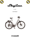
User Manual
.. d
do
o
m
m
w
w
.. cc
oo
.. cc
w
w
w
w
.. d
do
o
C
C
lliicc
kk
ttoo
bbuu
yy
ttoo
C
C
lliicc
kk
w
w
w
w
w
w
N
N
O
O
W
W
!!
P
PD
D
FF--
eerr
m
m
w
w
N
N
O
O
W
W
!!
ng
ge
an
eV
h
ha
Viiee
w
w
P
PD
D
C
X
XC
eerr
FF--
c kk
c
cu
ac
u -- tt rr a
y
o
c u -tr a c k
.c
TABLE OF CONTENTS
2
Warnings
About Power Assist Electric Bicycles
Product Components and Description
3
Installation
4
6
Check before Riding
Power Assist System Check (1)
9
Power Assist System Check (2) - Operation
9
Power Assist System Check (3) - LCD Control System
10
Battery and Charging
12
Care and Maintenance
Recommended Torque Value
14
Electric Bike Maintenance and Storage
15
Maintenance
16
Specification
17
Circuit Diagram
18
Please keep this manual properly after reading it.
1
.d o
m
o
w
w
w
.d o
C
lic
k
to
bu
y
bu
to
k
lic
C
w
w
w
N
O
W
!
h a n g e Vi
e
N
PD
!
XC
er
O
W
F-
w
m
h a n g e Vi
e
w
PD
XC
er
F-
c u -tr a c k
.c
h a n g e Vi
e
N
y
to
bu
lic
Refrain from the following activities as they may cause injury and
damage to your bike!
1.
Please regularly clean metal parts of electric bicycle. Use neutral detergent
and cloth to gently wipe the dirty place, then wipe with a dry cloth and
lubricate the related accessories.
2.
Regularly check the joints of frame, front fork, handler bar, brake and shock
absorber for any looseness or damage.
3.
Battery should be stored in dark and dry place and be charged at least one
time a month in case of long-term non-use.
4.
Please do not dismantle the bicycle body, controller, LCD display randomly.
Do not replace any spare parts by yourself to avoid any danger or bicycle
damage while using.
5.
The bicycle structure highly interacts with its function. Any private
reconstruction or replacement of components will affect normal operation
and safety performance of the bicycle, or shorten its service life.
6.
Inserting any metal object (like wire, copper coin, clip etc.) into the
terminals is prohibited.
7.
The used battery module when replaced is prohibited to be discarded in
the source of fire or high temperature environment. Please return it to the
dealer for recovery.
8.
Don’t drop or strike battery module. Huge external force will damage
battery case, the internal and the protection circuit, and the safety of the
user cannot be guaranteed.
9.
Using the non-original exclusive charger is prohibited. If the other brand
charger is used, adverse impacts will be incurred to the battery module, and
the warranty will be void.
10. Keep the lithium battery module dry, and placing the battery module in the
water is forbidden.
11. Conducting the fire and water resistance test for lithium battery module
and charger is forbidden.
12. The lithium battery module is designed specifically for the electric bicycle
and prohibit the use of other products.
13. When hands are wet, do not touch the power cord or plug.
14. Do not polish, drill or carve marks on bicycle body. Large scratch, puncture,
or carve may lead to cracks. If these exist, pay attention to the areas, or
replace with new accessories.
15. Do not install seat for child, for it may cause damage to the bicycle.
2
.d o
m
w
o
.c
C
m
c u -tr a c k
w
k
Warnings
o
.d o
w
w
w
w
w
C
lic
k
to
bu
y
N
O
W
!
XC
er
O
W
F-
w
PD
h a n g e Vi
e
!
XC
er
PD
F-
c u -tr a c k
.c
h a n g e Vi
e
w
N
y
bu
to
.c
.d o
m
w
o
m
c u -tr a c k
C
lic
k
About Power Assist Electric Bicycles
o
.d o
w
w
w
w
w
C
lic
k
to
bu
y
N
O
W
!
XC
er
O
W
F-
w
PD
h a n g e Vi
e
!
XC
er
PD
F-
c u -tr a c k
■Product Components and Description
Handlebar Set
Saddle
Battery
(please refer to P.9)
Pannier rack
Front Fork
Wheel hub motor
Mudguards
Spoke
Tire
Flywheel
Rim
Chain
Cover
Kickstand
Rear Derailleur
Pedal
Chain
Angle-Adjustable handlebar:
Front Brake
Valve
Accelerator
Display
Power-off
Brake Leve
r
■Attachments
1. Charger
2. Owner’s Manual
3. Battery Lock Key 1 set (Total 2 piece)
3
Handlebar
Shifter
.c
h a n g e Vi
e
N
y
to
bu
lic
.d o
Step.2 Fix front fork into the main-body and
then put 2 iron plates
Step.1 Fix the front wheel onto front fork
and confirm the quick-disassemble has
been tightened
Step.3 Put the tap and screw by turn, then
tighten and put into plastic cover
Step.4 Tighten the 2 screws on tap
Step.5 Put the seat well and confirm to
tighten quick-disassemble
Step.6 Assemble the foot pedal with
tool to finish the assembling.
4
m
w
o
.c
C
m
c u -tr a c k
w
k
■Installation
o
.d o
w
w
w
w
w
C
lic
k
to
bu
y
N
O
W
!
XC
er
O
W
F-
w
PD
h a n g e Vi
e
!
XC
er
PD
F-
c u -tr a c k
.c
h a n g e Vi
e
N
y
to
bu
lic
■Check before riding
1. Saddle height position: It is important to adjust the seat to a suitable height. when
the pedal is at the lowest position, sit on the saddle and step on the pedal. If your
leg can fully extend, you are at the optimal seat height. If your toe and leg can not
fully extend it will result in fatigue and can cause injury.
[1]Tire Specifications and maintenance
(1): Tire Pressure: Generally it will be marked on the edge of the tire
(2): Tire tread inspection: .When tires have lost their tread replace it.
[2]Wheel Rim Specifications
(1): Wheel rim spec: Aluminum alloy, double layer, 36 holes
(2): Wheel rim inspection: Wheel rim where is caused during braking. Wheel rim
has a safety line to indicate the level of use. When safety line has been worn
out, please replace the wheel rim.
(3): Wheel rim distortion inspection: Wheel rim distortion can cause the wheel to
wobble.
■Check before riding
4. Brake inspection:
[1]Clearance between brake block and wheel rim inspection: The distance between
brake block and wheel rim should be between 1-3mm. When brake block is worn
down, replace it to ensure proper braking. When riding in wet weather stopping
time is increased. Adjust your speed accordingly and allow for additional stopping
distance.
[2]Brake handle grip adjustment: When you stopping brake handle should depress
about half way towards the grip, if brake handle extends closer to the grip, the
space between brake block and wheel rim is too great and should be adjusted
accordingly.
[3]Brake inner wire: Outlet end of brake inner wire should avoid fork. Cover brake
wire end with an aluminum cap. You should apply lubricant to brake wire
periodically to maintain smooth action and prevent rust.
[4]Do not apply lubricant to brake.
5
.d o
m
w
o
.c
C
m
c u -tr a c k
w
k
Check before Riding
o
.d o
w
w
w
w
w
C
lic
k
to
bu
y
N
O
W
!
XC
er
O
W
F-
w
PD
h a n g e Vi
e
!
XC
er
PD
F-
c u -tr a c k
.c
F-
w
y
c
6. Throttle
(In the 100% electric power mode)
to
k
lic
m
c u -tr a c k
Rotate the (left) grip of throttle downward to make
bike go forward and loose the grip to slow down
the bike. If your loose the grip completely, the bike
will stop power output. While riding, accelerate
the bike slowly to maintain riding safety. It’s
advised that all power supply is shut down if you
stop the bike, to prevent from operating the
throttle improperly and micro power consumption
of battery.
7. Quick Release
Please make sure the quick release is tightened.
a. Front Wheel
Released
b. Seat Post
Tightened
Released
Tightened
8. Other attachment:
.d o
o
.
ack
C
m
w
o
c u -tr
bu
y
bu
C
lic
k
to
5. Shift Grip:Style of speed changing handle bar: Rotary (Grip Shift) 7 speeds
w
w
.d o
w
w
w
w
N
O
W
!
h a n g e Vi
e
N
O
W
XC
er
PD
h a n g e Vi
e
!
XC
er
PD
F-
Reflectors
6
.c
F-
w
y
to
k
lic
Precautions before Riding:
1.
2.
Wear the helmet before riding.
Wear bright but not over-generous clothes to prevent them from involved in the
operating components.
3. Check the brakes and body parts for brake failure and parts looseness or
wastage.
4. Make sure the wheels are securely fixed.
5. Check that the tires are cracked, damaged, or abnormally worn. Following the
label on the tires, maintain the tire pressure within the range indicated. Check
the wheels are deformed.
6. Unplug the Key and keep it safe to avoid lose and also to prevent breakage due
to collision while riding.
7. The total load must not exceed 100 kg (people and objects).
8. Carry spare consumables before riding: tires, inner tubes and brake blocks ... etc.
9. Install the lights when riding at night. When riding on public roads, please use
the illumination lights and reflectors in accordance with the provisions of the
national laws and regulations.
Precautions When Riding:
1.
2.
3.
4.
5.
6.
7.
8.
9.
When riding, if abnormal condition or parts damage occur affecting riding safety,
do not continue riding. Check the main area to do the appropriate
troubleshooting.
When riding, prohibit let go riding or stunts.
Warning: in rain or wet weather, slippery road surfaces may increase braking
distance.
Do not ride on rough road, to avoid damage or puncture to the electric bicycle.
Continuous climbing will cause the temperature rise of motor and the motor will
not provide the power for self-protection.
When riding, prohibit let go riding or stunts.
Adjust the auxiliary power according to the road conditions, and do not use
auxiliary power during downhill in order to avoid danger.
For safety reasons, do not ride in heavy rain, snow, and strong winds.
Please stay away from puddles. If the water level reaches motor, the circuit of
motor will be damaged by water.
CAUTION
If the power assist electric bicycle has any damage or needs adjustment, please
contact the where you purchased it. Don’t repair by yourself. Repairs of power
assist electric bicycle should be preformed by trained professionals with the correct
tools. Improper repair will result in damage of the bicycle or serious accidents.
7
.d o
o
w
m
C
m
■While riding your bike, please observe below points for
your safety:
o
c
bu
y
bu
to
k
lic
C
c u -tr
.
ack
w
w
.d o
w
w
w
w
N
O
W
!
h a n g e Vi
e
N
O
W
XC
er
PD
h a n g e Vi
e
!
XC
er
PD
F-
c u -tr a c k
.c
F-
!
O
W
y
to
k
lic
Power assist system will not work normally if the battery is not installed and locked
in place.
Check battery status before riding
Ensure all wires are good and all connections are securely locked and fastened.
Don’t disassemble the bodywork, controller and panel without proper instruction.
■ Power Assist System Check (2) Battery Lock Function and Operation
CAUTION :
Put the battery into the frame and check whether it is inserted securely.
Don’t remove the battery while starting the power
When inserting the battery, listen for a click to indicate it was inserted correctly
●Battery taking out steps
1. Turn off power
2. Turn the key towards to open
and do not release
3. Pull the battery as figure showing
4. Take out battery
●Correct Position of Battery:
Stem handle is in the front
8
.d o
o
c
m
C
m
o
c u -tr
.
ack
w
w
w
.d o
bu
y
bu
to
k
lic
C
w
w
w
N
O
W
h a n g e Vi
e
N
■ Power Assist System Check (1)
XC
er
PD
w
!
h a n g e Vi
e
w
PD
XC
er
F-
c u -tr a c k
.c
F-
!
O
W
y
to
k
lic
c
1. DISPLAY WINDOWS
.d o
m
o
o
c u -tr
.
ack
C
m
w
w
w
.d o
bu
y
bu
to
k
lic
C
w
w
w
N
O
W
h a n g e Vi
e
N
■ Power Assist System Check (3) LED control system
XC
er
PD
w
!
h a n g e Vi
e
w
PD
XC
er
F-
c u -tr a c k
3 levels kinetic energy asistance
Speed unit
Setting knob
(program mode)
Speed
Single mileage
Backlight switch
Time display
Total accounting
mileage
Quantity of
electricity display
ON/OFF switch
Adjustment knob
Power display
light
Flash and please do
not start motor
Electricity
quantity
10%↓
2. Program mode(press
1Bar
2Bar
3Bar
4Bar
5Bar
10%
30%
50%
70%
90%↑
for 3seconds to enter program mode, press
for
10seconds to cancel it and single mileage will back to 0 , the mode will change to
the mode that the value back to 0 when starting)
1) Under program mode, the keys instruction as below:
set
Change page
Adjustment key
2) Program mode operation:
Function
program
Operation method
“total mileage” windows show
Press
1
Wheel
diameter
setting(inch)
Remark
HEEL
to change the setting value, the value will
show16→ 18→ 20→ 22→ 24→ 26→ 28→ 29→ 30 under
speed windows(take inch for unit)
Press
for storing and changing page, press
3seconds for storing and jumping to main windows
9
Default
value
26”
for
(16 ~ 30)
.c
h a n g e Vi
e
w
N
y
bu
to
2
unit
w
Speed unit Press
to change the setting from km to mile
setting
when under speed windows
English/metri
c
Press
for storing and changing windows, press
.d o
3
Total
kilomters
Delete 0
setting
to change windows, “total mileage” windows will
flash
Press
1second, you can delete total mileage to “0”
Press
for storing and changing windows, press
3seconds for storing and change to main interface
Press
4
Recovery to
Press
manufacturin
g setting
Press
to the windows that total mileage will
dEF
1 seconds to recovery to default setting
for storing and changing windows, press
3seconds for storing and change to main interface
3. Other function(the functions that can’t setting on LCD)
●TRIP windows’ decimal point will flash when out of connecting with brake power off system
●LCD is not working or riding within minutes, LCD will auto power off and enter dormancy mode
●Under program mode and no operation within 15seconds, systems will auto back to main interface
4. LCD CODE UNUSUAL DISPLAY LIST:
LCD
A_1
reason
Li-battert’s voltage is too low
36V system: under 32V
A_2
Brake is stuck or short circuit
A_3
Accelerator is stuck or short circuit
A_4
AB SENSOR is no signal or no phase
A_6
Control temperature is over 70℃
A_7
A_15
Motor is unusual
Controller is unusual
The connecting for LCD meter and
controller is failed.
Trouble shooting method
Check the battery power, replace batter
or charge the battery
Check if the brake is stuck , take off
brake wire
Turn the accelerator to the original
position and auto back to normal
condition
Check if the AB8 magnet distance is too
big or without signal and can’t
connecting well
Turn off power and wait for
temperature down ,then it will auto
back to normal
Send back to manufactory for checking
restart
10
c u -tr a c k
Default
value
km
(km、mile)
3seconds for storing and change to main interface
Press
m
, “total mileage windows” will show
o
.c
lic
k
c u -tr a c k
C
m
Press
o
.d o
w
w
w
w
w
C
lic
k
to
bu
y
N
O
W
!
XC
er
O
W
F-
w
PD
h a n g e Vi
e
!
XC
er
PD
F-
remark
Start and testing
for 2 seconds
Start and testing
for 2 seconds
Start and testing
for10 seconds
.c
F-
!
O
W
y
to
k
lic
c
CAUTION
1. Please read this manual and safety rules thoroughly before using the Lithium
battery pack.
2. The battery pack capacity should be lower than 50% when being transported
according to transportation rules. Charge for 12 hours with the charger
supplied before the first use.
3. Please charge with the charger supplied by original manufacturer. Do not use
third party chargers
4. Battery will drain during long periods of disuse.
Switch
1. Charging Steps
Charging Seat
Battery Output Terminal
Plug the power plug of the charger into power source.
The charger’s LED indicator light will be green (as DWG 1).
Connect the charger output to the battery pack input. After 1 the LED indicator
of the charger will change to orange, (as DWG 2).
When LED indicator changes to green light, the battery pack is fully charged.
Power-off protection will start automatically and the light will extinguish (as
DWG 3). Total charge time will be about 4~5 hours. An initial charge of 12 hours
is required before the first use.
After lithium battery pack is fully charged, disconnect the charger from the
battery and pull out the power cord from the socket. Proper charge temperature
is 0~45 degrees Celsius.
1
2
3
11
.d o
m
o
o
c u -tr
.
ack
C
m
w
w
w
.d o
bu
y
bu
to
k
lic
C
w
w
w
N
O
W
h a n g e Vi
e
N
■ Battery and Charging
XC
er
PD
w
!
h a n g e Vi
e
w
PD
XC
er
F-
c u -tr a c k
.c
h a n g e Vi
e
w
N
y
bu
to
k
lic
c u -tr a c k
CAUTION
1. After lithium battery is fully charged, don’t leave the charger connected to
the battery for extended periods.
2. This lithium battery is specified for Manhattan Power Assist Electric
Bicycle. Don’t use it with other product.
3. Insert the battery into the bicycle securely and check all the terminals
connections are locked and fastened securely.
4. It is normal for the charge and battery to become warm during charging.
5. When not in use for extended periods of time keep the battery in a well
ventilated area and recharge it once a month to maximize battery life.
2. Specification of Lithium Battery
Standard Voltage:DC36V
Standard Capacitance:8.8Ah
Voltage Range:DC30.0V ~ 42V
Maximum Output Current:15A
3. Attachments of Lithium battery:
Power Cord X 1 piece
Charger X 1 piece
Charger Spec: Input 100 ~ 240VAC,50/60Hz,1.2A
Output 42V,2.0A
12
w
.d o
o
.c
m
C
m
o
.d o
w
w
w
w
w
C
lic
k
to
bu
y
N
O
W
!
XC
er
O
W
F-
w
PD
h a n g e Vi
e
!
XC
er
PD
F-
c u -tr a c k
.c
h a n g e Vi
e
N
y
to
bu
lic
Handlebar to Stem,
5-6N.m
Stem to Fork Tube ,
9-10N.m
Locking Torque Value of
Screw for Adjusting Angle,
17-18.5Nm
Locking Torque Value of Joint between
Seat and Seat Post , 20-21Nm
Locking Torque Value of
Axis, 380-420Kg-m
13
.d o
m
w
o
.c
C
m
c u -tr a c k
w
k
Recommended Torque Value
o
.d o
w
w
w
w
w
C
lic
k
to
bu
y
N
O
W
!
XC
er
O
W
F-
w
PD
h a n g e Vi
e
!
XC
er
PD
F-
c u -tr a c k
.c
h a n g e Vi
e
N
y
to
bu
lic
■ Electric Bike Maintenance and Storage
Bring the bicycle in to an authorized repair shop for periodic maintenance
Check whether brakes and tires are in good condition.
Clean the metal parts of the bicycle with soft cloth and lubricate parts where
necessary.
Keep tires inflated to the pressure indicated on the tire wall.
(Tire Pressure Range: 40 psi)
Store the bike indoors or in a protected area.
Prolonged exposure will shorten the life of your bicycle.
If unused for prolonged periods charge the battery once a month and store in
a well ventilated area
Inspect your bike and lubricate the chain regularly.
Keep lithium battery pack dry.
Do NOT insert any metal objects (such as wires, copper coins, clip) into the
battery.
Only use charger supplied by the manufacturer or authorized dealers.
Do NOT knock the battery pack for it may cause damage to battery and circuit.
If battery pack reaches a high temperature while using or charging, stop using
it and contact the dealer.
Check the rusty position carefully if there is any crack. Rust will result in crack
and damage of the bodywork and its components.
Clean your favorite bicycle and lubricate the components. Keep your bicycle
away from corrosive objects, such as salinity.
14
.d o
m
w
o
.c
C
m
c u -tr a c k
w
k
Care and Maintenance
o
.d o
w
w
w
w
w
C
lic
k
to
bu
y
N
O
W
!
XC
er
O
W
F-
w
PD
h a n g e Vi
e
!
XC
er
PD
F-
c u -tr a c k
.c
F-
!
O
W
y
to
k
lic
c
Many factors will make the parts to become damaged loose or worn out while using
this power assist electric bicycle. If you don’t inspect it regularly, it will shorten the life
of the bike. New bicycles should be inspected carefully after 2 months. Future
maintenance should be done every 6 months.
Maintenance Items and Interval
Symbol definition: Adjustment(◆)
Replace:(★)
Inspection(■)
Maintenance Items
Tire pressure
Saddle height and angle, Upright height
Front fork revolving,
pedals and BB principal axis
front wheel motor axes and rear wheel
inner shift hub
chain tension
front and rear brakes
brake handle (grip distance).
brake block wear
large and small Crank set
wheel rim distortion
spokes
frame and front fork
All screws
Tighten:(▲) Lubricate:(●)
New
2months
6months
1year
1.5year
◆
◆
◆
◆
◆
◆▲
■
◆
◆
◆
▲
■
■▲
■▲●
■▲
▲
■
■●
◆■
◆ ■●
▲
■
■
◆■
◆■
◆
■●
■●
■●
■●
◆
■
◆
◆■
◆■
◆
■
◆■
◆■
◆■
▲
■
■
◆■
◆■★
■
■
■
■
■
■
◆■
◆■
■
■
◆■
◆■
■
■
■
■
■
■
■
■
◆
▲
15
.d o
m
o
o
c u -tr
.
ack
C
m
w
w
w
.d o
bu
y
bu
to
k
lic
C
w
w
w
N
O
W
h a n g e Vi
e
N
■ Maintenance
XC
er
PD
w
!
h a n g e Vi
e
w
PD
XC
er
F-
c u -tr a c k
.c
h a n g e Vi
e
N
y
to
bu
lic
Black
Color
Size
26”
28”
6061 AL Alloy
Frame
CrankSet
Gear 44T 1/2”x3/32”x170mm
R/Derailleur
Shimano RS-43-7R
Shifter
Shimano RS-43-7R
Chain
1/2”x3/32”
Brake
F/R Disc Brake
Handle Bar
Stem
Seat Post
L=600mm H=38mm Al Alloy
28.6x31.8x100mm AL Alloy
Φ30.4x300mm AL Alloy
Wheel Rim 14G 26”x36H-AV BK/CNC
Spoke
14G 28”x36H-AV BK/CNC
13G Stainless, Brass Nipple
Tire G701 26"x1.95C A/V BK
G701 28"x1.95C A/V BK
Power System Specification
Motor
36V 500W DC Brushless Hub Motor
Battery
36V 8.8Ah Lithium Battery
Charger
42V 2A Charger
Display
LCD console
Sensor Device
Speed Sensor
16
.d o
m
w
o
.c
C
m
c u -tr a c k
w
k
Specification
o
.d o
w
w
w
w
w
C
lic
k
to
bu
y
N
O
W
!
XC
er
O
W
F-
w
PD
h a n g e Vi
e
!
XC
er
PD
F-
c u -tr a c k
.c
h a n g e Vi
e
w
N
y
bu
k
to
3 red
.d o
2 orange
1 brown GND
2 red 5V
3 orange SNB
4 yellow SNA
1 red
black
white
green
orange
2 black
1 red 24V (positive pole)
2 black GND (negative pole)
2 green GND
green
red
brown
Lower controller
1 gray BKS
red
blue
black GND
red 5V
white HS signal
green spare
orange spare
brown spare
blue spare
2 blue
5 green
4 white
1 yellow
3 green
1 yellow U
2 blue V
3 green W
6 yellow
4 white LSN(Speed)
5 green HW Hall
6 blue HW Hall
7 yellow HW Hall
8 red 5V
9 black GND
4 brown 3 red
Circuit
Diagram
8 red
9 black
7blue
1 brown GND
3 yellow A
2 orange B
1 red 15V
1 yellow 2 orange
V1.0 2013/6/5
17
m
w
.c
o
m
o
1 yellow
lic
4 brown
lic
C
c u -tr a c k
w
w
.d o
w
w
w
C
k
to
bu
y
N
O
W
!
XC
er
O
W
F-
w
PD
h a n g e Vi
e
!
XC
er
PD
F-
c u -tr a c k
.c


