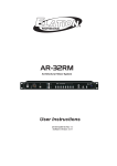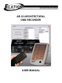
1
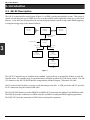
:,7+(92/87,21&20(6&+$1*(
AR-32 ARCHITECTURAL
DMX RECORDER
USER MANUAL
AR-32 User Manual
Manual Revision:
May 2008
Software Revision:
Version 2.09
2
Elation Professional ®
Table of Contents
1.
Elation Support ............................................................................................................................................... 4
1.1
Thank You for Purchasing the AR-32 .................................................................................................... 4
1.2
Customer Service .................................................................................................................................... 4
1.3
2-Year Limited Warranty........................................................................................................................ 5
2. General Information........................................................................................................................................ 6
2.1
Safety ...................................................................................................................................................... 6
2.2
Compliance ............................................................................................................................................. 7
2.3
Abbreviations.......................................................................................................................................... 7
3. Introduction..................................................................................................................................................... 8
3.1
AR-32 Description .................................................................................................................................. 8
3.2
Manual Conventions ............................................................................................................................... 9
4. Specifications................................................................................................................................................ 10
4.1
AR-32 Components .............................................................................................................................. 10
4.2
AR-32 Features ..................................................................................................................................... 11
5. Installation .................................................................................................................................................... 12
5.1
Unpacking Contents.............................................................................................................................. 12
5.2
Cabling Requirements........................................................................................................................... 12
5.3
Installation Procedtures......................................................................................................................... 14
5.3.1
Wall-mounting the AR-32C.......................................................................................................... 14
5.3.2
Desktop mounting the AR-32C .................................................................................................... 14
5.4
Setup Procedures................................................................................................................................... 15
5.4.1
Software Installation ..................................................................................................................... 15
5.4.2
System Connection ....................................................................................................................... 15
5.4.3
Software Launch ........................................................................................................................... 15
6. Operation ...................................................................................................................................................... 16
6.1
AR-32C Controls & Connections ......................................................................................................... 16
6.2
AR-32P Controls & Connections ......................................................................................................... 17
6.3
AR-32 IR Remote Controls .................................................................................................................. 18
6.4
DMX Channels ..................................................................................................................................... 19
6.5
Software Overview ............................................................................................................................... 20
6.5.1
Main Screen .................................................................................................................................. 20
6.5.2
Show Edit Screen.......................................................................................................................... 27
6.5.3
Events Edit Screen ........................................................................................................................ 32
6.6
Programming Tips ................................................................................................................................ 36
7. Service .......................................................................................................................................................... 37
7.1
Maintenance.......................................................................................................................................... 37
7.1.1
General Inspection ........................................................................................................................ 37
7.1.2
Basic Cleaning .............................................................................................................................. 37
7.2
Troubleshooting .................................................................................................................................... 38
www.elationlighting.com
3
AR-32 User Manual
1. Elation Support
1.1 Thank You for Purchasing the AR-32
1
Thank you for your purchasing the Elation Professional AR-32 Architectural Recorder System. Please read the
instructions in this manual carefully and thoroughly before attempting to operate this unit. These instructions
contain important information regarding safety during use and maintenance. Please fill out and return the
enclosed warranty card to validate your purchase.
1.2 Customer Service
Elation provides a toll free customer support line, to provide set up help and to answer any question should you
encounter problems during you set up or initial operation. You may also visit us on the web at
www.elationlighting.com for any comments or suggestions.
All returned service items whether under warranty or not, must be freight pre-paid and accompany a Return
Authorization (RA) number. The RA number must be clearly written on the outside of the return package. Items
returned without a RA number clearly marked on the outside of the package will be refused and returned at
customer’s expense. You may obtain a RA number by contacting customer service.
A brief description of the problem as well as the RA number must be written down on a piece of paper and
included in the shipping container. If the unit is under warranty, you must also provide a copy of your proof of
purchase invoice.
Customer Service hours are Monday through Friday 8:00 a.m. - 5:00 p.m. Pacific Standard Time.
Toll Free: (866) 245-6726
Phone: (323) 582-3322
Fax: (323) 832-9142
Information: [email protected]
Sales: [email protected]
Support: [email protected]
Forum: http://forums.elationlighting.com
4
Elation Professional ®
1.3 2-Year Limited Warranty
Elation hereby warrants, to the original purchaser, Elation Professional products to be free of manufacturing
defects in material and workmanship for a period of 2 Years (730 days) on all internal parts, components, and
labor. This warranty shall be valid only if the product is purchased within the United States of America,
including possessions and territories. It is the owner’s responsibility to establish the date and place of purchase
by acceptable evidence, at the time service is sought.
For warranty service, send the product only to the Elation factory. All shipping charges must be pre-paid. If the
requested repairs or service (including parts replacement) are within the terms of this warranty, Elation will pay
return shipping charges only to a designated point within the United States except Hawaii or Alaska. If the entire
instrument is sent, it must be shipped in its original package. No accessories should be shipped with the product.
If any accessories are shipped with the product, Elation shall have no liability whatsoever for loss of or damage
to any such accessories, nor for the safe return thereof.
This warranty is void if:
•
•
•
•
The serial number has been altered or removed
The product is modified in any manner which Elation concludes, after inspection, affects the reliability of
the product
The product has been repaired or serviced by anyone other than the Elation factory unless prior written
authorization was issued to purchaser by Elation
The product is damaged because it was not properly maintained as set forth in the instruction manual
This is not a service contract, and this warranty does not include maintenance, cleaning or periodic check-up.
During the period specified above, Elation will replace defective parts at its expense, and will absorb all
expenses for warranty service and repair labor by reason of defects in material or workmanship. The sole
responsibility of Elation under this warranty shall be limited to the repair of the product, or replacement thereof,
including parts, at the sole discretion of Elation. All products covered by this warranty were manufactured after
January 1, 1990, and bear identifying marks to that effect.
Elation reserves the right to make changes in design and/or improvements upon its products without any
obligation to include these changes in any products theretofore manufactured.
No warranty, whether expressed or implied, is given or made with respect to any accessory supplied with
products described above. Except to the extent prohibited by applicable law, all implied warranties made by
Elation in connection with this product, including warranties of merchantability or fitness, are limited in duration
to the warranty period set forth above. And no warranties, whether expressed or implied, including warranties of
merchantability or fitness, shall apply to this product after said period has expired. The consumer’s and/or
Dealer’s sole remedy shall be such repair or replacement as is expressly provided above; and under no
circumstances shall Elation be liable for any loss or damage, direct or consequential, arising out of the use of, or
inability to use, this product.
This warranty is the only written warranty applicable to Elation Products and supersedes all prior warranties and
written descriptions of warranty terms and conditions heretofore published.
www.elationlighting.com
5
1
AR-32 User Manual
2. General Information
2.1 Safety
The following symbols are used throughout this manual:
Indicates potential injury or death to persons.
Indicates potential damage to equipment.
2
Indicates items may be recycled.
The following safety information relates to the AR-32 Architectural Recorder System. Please read each item
carefully to ensure you fully understand them.
To prevent the risk of electrical shock, do not open this unit. There are no user serviceable
parts inside this unit. Do not attempt any repairs yourself. Doing so will void your
manufactures warranty. Should your unit require service, please contact your nearest Elation
dealer or Elation Customer Service.
To prevent or reduce the risk of electrical shock or fire, do not expose this unit to rain or
moisture. Do not remove the plug ground pin or connect to an ungrounded circuit.
This unit is not designed for use by persons under the age of 12. Use only under adult
supervision.
Turn off the power if not using this unit for a long time.
6
Elation Professional ®
2.2 Compliance
The CE marking (an acronym for the French "Conformite Europeenne") certifies that a product has
met EU health, safety, and environmental requirements, which ensure consumer safety. A
manufacturer that has gone through the conformity assessment process may affix the CE marking to
the product.
The AR-32 system has passed internal testing based on the EN55015:2001 standard, and is 100% CE compliant.
We certify that the product conforms to the protection requirements of council directives 73/23/EEC (LVD) and
89/336/EEC (EMC).
2.3 Abbreviations
2
CD – Compact Disc
DMX – Digital Multiplex
Gb – Gigabyte
Ghz – Gigahertz
IR – Infra Red
LAN – Local Area Network
Mb – Megabyte
PC – Personal Computer
RA – Return Authorization
RAM – Random Access Memory
RGB – Red, Green, Blue
USB – Universal Serial Bus
XLR – 3-pin Cannon X connector, with Latch and Rubber guard
www.elationlighting.com
7
AR-32 User Manual
3. Introduction
3.1 AR-32 Description
The AR-32 Architectural Recorder System (Figure 1) is a DMX recording and playback system. This system is
capable of controlling any type of DMX device by recording a DMX control signal and saving it to a scene file in
memory. Scene files may be played back at any time using the manual controls, using remote DMX triggering,
or using timed triggering via the internal software.
A R - 3 2 IR
R e m o te
A R -3 2 C
C o n tr o lle r
U S B C a b le
A R -3 2 P C
S o ftw a r e
C a te g o r y 5 E th e r n e t
L A N C a b le
A R -3 2 P D M X
In te r fa c e
1 2 0 V A C -6 0 H z
D M X D a ta C a b le
( D M X IN )
3
D M X D a ta C a b le
(D M X O U T )
DMX
C o n tr o lle r
( n o t in c lu d e d )
DMX
F ix tu r e
( n o t in c lu d e d )
DMX
F ix tu r e
( n o t in c lu d e d )
T e r m in a to r
Figure 1
6
The AR-32C Controller may be installed in any standard 1-gang wall box or mounted for desktop use with the
included stand. The controller may be operated remotely using the included AR-32 IR remote control. The AR32C connects to the AR-32P DMX Interface using industry standard Category 5 Ethernet LAN cable.
AR-32 System Control Software is used to record and manage scene files. A USB port on the AR-32C provides
for PC connection using the included USB cable.
The AR-32P DMX Interface provides DMX IN and DMX OUT connections for standard 3-pin DMX data cable.
The DMX IN provides connection to a DMX controller for DMX recording and DMX triggering operations.
The DMX OUT provides connection to DMX fixtures for playback operations.
8
Elation Professional ®
3.2 Manual Conventions
The following terms and conventions are used throughout this manual:
•
•
•
•
•
•
Buttons and switches are presented using their exact spelling and capitalization and surrounded by
brackets (i.e. press the [PAGE 1] button).
Activate is used with switches/buttons that toggle between two values and means place the control in its
active state.
Deactivate is used with switches/buttons that toggle between two values and means place the control in
its non-active state.
Intercancel means that pushing one button simultaneously selects that button and automatically
deselects the previously selected button. One button is always active. For example, the [SHOW] buttons
intercancel.
Select describes pointing to and clicking a button or checkbox (on a software screen) such that it is
activated. This allows a single instruction to describe this action without knowing the control’s previous
state. For example, if the control is not selected, clicking the control once selects it. If it is already
selected, no action is required.
Highlight describes the outlining of selected text or files with a colored border to make it stand out. For
example, this text is highlighted. Text may be highlighted by clicking and dragging the cursor across the
portion desired.
This manual is Copyright © 2008 Elation Professional. All rights reserved. No part of the manual included with
this product can be reproduced or transmitted in any form, by any means, for any purpose without prior written
authorized permission.
Information contained in this manual is subject to change at any time and without notice. Please contact Elation
Customer Service or visit www.elationlighting.com for the latest manual revisions.
www.elationlighting.com
9
3
AR-32 User Manual
4. Specifications
4.1 AR-32 Components
The AR-32 Architectural Recorder System (Figure 2) is composed of the following components:
•
•
•
•
•
AR-32C Controller
AR-32P DMX Interface
Ethernet LAN Cable (Category 5 with RJ-45 connectors)
AR-32 IR Remote
AR-32 System Control Software and USB Cable
AR-32C Controller
AR-32P DMX Interface
AR-32 IR Remote
4
USB Cable
Category 5 LAN Cable
Figure 2
The AR-32 comes pre-loaded with 32 shows designed for use with RGB type LED fixtures (strips, cubes, panels,
etc.). Shows 1-16 include static color scenes and Shows 17-32 include various rainbow chases. All factory
scenes are written for 512 DMX channels.
10
Elation Professional ®
4.2 AR-32 Features
The AR-32 Architectural Recorder System is a lighting control system that records DMX signals from a separate
controller and saves these recordings to scene (.scn) files for future playback. Multiple scenes may be loaded to
each controller show location. Shows may be played back manually using the AR-32 Controller, remotely using
the IR remote or a DMX signal, or internally triggered using time and date.
The AR-32 software is also capable of converting Adobe Flash animations into RGB pixel data for playback on
LED fixtures. Up to 170 pixels in any orientation may be converted from Flash (.swf) file format to DMX scene
(.scn) file format.
The AR-32 Architectural Recorder System has the following features:
•
•
•
•
•
•
•
•
•
•
•
•
•
•
512 DMX Channel recording
Flash (.swf) file playback and conversion
Up to 32 shows (4 pages, 8 shows per page)
Up to 16 scenes per show, with 248 scene file capacity
128Mb memory maximum
Memory retained upon power failure
Real time individual triggering of desired scenes
Playback via DMX Control Mode
Playback via Timed Trigger Mode
Playback via Manual Mode
AR-32 System Control Software for controller configuration
AR-32C USB communication port for PC link
Infrared remote control
Wall-mount or free standing desktop controller installation
•
•
•
•
Power input: 120VAC - 60Hz
Fuse: F0.5A 250V 5x20mm
Dimensions: 57x74x43mm
Weight: approx 0.2kg
4
6
The AR-32 system software has the following minimum hardware requirements:
•
•
•
•
CPU: Pentium 4 - 2 Ghz
RAM: 512 Mb
Hard Disk: 20 Gb free space
Video: 128 Mb RAM
www.elationlighting.com
11
AR-32 User Manual
5. Installation
5.1 Unpacking Contents
When first opening your AR-32 Architectural Recorder System, please ensure that all system components are
present. The system ships with the following components:
•
•
•
•
•
•
AR-32C Controller & Stand
AR-32P DMX Interface
50’ Category 5 Ethernet LAN Cable
AR-32 IR Remote
AR-32 System Control Software CD
AR-32 User Manual
Upon unpacking, carefully inspect your unit for any damage that may have occurred during shipping. If damage
has occurred, do not plug the unit in. Contact your Elation dealer as soon as possible.
Do not discard packing carton in the trash. Please recycle whenever possible.
5.2 Cabling Requirements
5
The AR-32P provides power to the system and plugs into any standard 120VAC – 60Hz grounded receptacle.
The AR-32C receives power from the AR-32P via the Category 5 Ethernet LAN cable (Figure 3) that connects
the two components.
Figure 3
The AR-32 does not use standard Ethernet protocol, and cannot be used with Ethernet routers
or switches.
12
Elation Professional ®
The AR-32P also provides DMX IN and DMX OUT 3-pin XLR connectors (Figure 4) for DMX recording,
control, and playback operations. Use only cable rated for DMX512 data transmissions.
Figure 4
Data cabling should meet the following USITT DMX512 specification requirements:
•
•
•
•
•
•
•
Low capacitance
Two twisted pairs
Foil or braid shielded
Suitable for use with EIA485 (RS485) operation at 250k baud
Characteristic impedance 85-150 ohms, nominally 120 ohms
24 AWG min. gauge for runs up to 1000 feet (300m)
22 AWG min. gauge for runs up to 1640 feet (500m)
Microphone cables and other general purpose, two-conductor audio or signal cables are not
suitable for use with DMX512.
5
www.elationlighting.com
13
AR-32 User Manual
5.3 Installation Procedures
The AR-32 Architectural Recorder System can be installed in one of two ways, wall-mount or desktop.
5.3.1 Wall-mounting the AR-32C
1. Remove the back cover of the AR-32C by removing the retaining screw at the base of the controller and
snapping the cover off.
2. Pull the Category 5 Ethernet LAN cable RJ-45 connector through the center hole on the back cover
(Figure 5).
3. Using the pre-drilled holes, connect the back cover to a 1-gang wall box.
4. Connect the RJ-45 connector to the front portion of the controller.
5. Snap the front of the controller onto the back cover and replace the retaining screw.
Figure 5
5
5.3.2 Desktop mounting the AR-32C
1. Remove the back cover of the AR-32C by removing the retaining screw at the base of the controller and
snapping the cover off.
2. Using the four pre-drilled holes, connect the back cover to the included desktop stand (Figure 6).
3. Pull the Category 5 Ethernet LAN cable RJ-45 connector through the center hole on the back cover and
stand, and connect the RJ-45 connector to the front portion of the controller.
4. Snap the front of the controller onto the back cover and replace the retaining screw.
Figure 6
14
Elation Professional ®
5.4 Setup Procedures
5.4.1 Software Installation
Install the AR-32 System Control Software as follows:
1. Insert the AR-32 System Control Software CD into a CD drive on PC.
2. Locate the AR-32 SetupRevX.XX.exe application (Figure 7) on the CD and double-click to begin
installation.
Figure 7
3. Follow the prompts to complete install.
5.4.2 System Connection
To set up the AR-32 Architectural Recorder System for operation, connect the system components together as
follows:
1. Connect the AR-32C Controller and AR-32P DMX Interface using Category 5 Ethernet LAN Cable.
2. Plug the AR-32P power cable into a 120VAC – 60Hz receptacle. Activate the [POWER] switch on the
front of the AR-32P.
3. Connect DMX source (such as a console or other controller) to the DMX IN on the AR-32P.
4. Connect DMX fixtures to the DMX OUT on the AR-32P.
5. Complete software installation before performing this step. To configure the AR-32 system, connect
the AR-32C to a PC using the USB link cable. Windows will prompt for driver installation.
5.4.3 Software Launch
Launch the AR-32 System Control Software as follows:
1. From the Windows desktop, select Start > Programs > Elation AR-32 > AR-32.
www.elationlighting.com
15
5
AR-32 User Manual
6. Operation
6.1 AR-32C Controls & Connections
The AR-32C Controller (Figure 8) has the following controls and connections. Each is described in Table 1.
1
2
3
4
5
6
7
8
Figure 8
Table 1
No.
Name
1 [PAGE]
6
2
3
4
5
6
7
8
16
Description
[PAGE] buttons (1-4) allow user to select from four pages (banks) of shows.
Indicator (blue LED) shows selected page
[SHOW]
[SHOW] buttons (1-8) allow user to select individual scenes within a selected page.
Indicator (blue LED) shows selected show.
[MASTER UP]
[MASTER UP] button offers intensity control by increasing all 512 DMX channel
values from 0-255 or 0-100%.
[MASTER DOWN] [MASTER DOWN] button offers intensity control by decreasing all 512 DMX
channel values from 255-0 or 100-0%.
[OFF]
[OFF] button turns the system off. Indicator (blue LED) shows system is off.
[AUTO/
[AUTO/MANUAL] button toggles between Automatic and Manual operation
MANUAL]
modes when held for 2 seconds. Indicator shows Automatic (red LED) or Manual
(blue LED) modes.
USB Port
USB port allows connection to a PC with AR-32 software.
IR Sensor
IR sensor receives signals from AR-32 IR remote.
Elation Professional ®
The AR-32 is capable of holding up to 32 shows in memory, limited by a memory size of 128 Mb. Shows are
configured using the AR-32 System Control Software. When operating the AR-32 in Manual mode, the 32
shows are mapped to the controllers [SHOW] buttons. Table 2 explains the show mappings used by the AR-32.
Table 2
Button
[PAGE1]
[PAGE2]
[PAGE3]
[PAGE4]
[SHOW1] [SHOW2]
Show1
Show2
Show9
Show10
Show17
Show18
Show25
Show26
[SHOW3]
Show3
Show11
Show19
Show27
[SHOW4]
Show4
Show12
Show20
Show28
[SHOW5]
Show5
Show13
Show21
Show29
[SHOW6]
Show6
Show14
Show22
Show30
[SHOW7] [SHOW8]
Show7
Show8
Show15
Show16
Show23
Show24
Show31
Show32
6.2 AR-32P Controls & Connections
The AR-32P DMX Interface (Figure 9) has the following controls and connections described in Table 3.
FRONT
BACK
1
2
3
4
5
6
Figure 9
Table 3
No.
1
2
3
4
Name
[POWER]
FUSE
Power IN
DMX IN
5
DMX OUT
6
TO AR-32C
6
Description
[POWER] switch turns the system on and off.
FUSE connection allows user to replace the power supply fuse.
Power IN cable provides AC power connection to the system.
DMX IN provides data connection from DMX sources via 3-pin
XLR connector.
DMX OUT provides data connection to DMX fixtures via 3-pin
XLR connector.
TO AR-32C provides data connection to AR-32C controller via RJ45 connector.
www.elationlighting.com
17
AR-32 User Manual
6.3 AR-32 IR Remote Controls
The AR-32 IR Remote (Figure 10) has the following controls and indicators. Each control is described in
Table 4.
1
3
2
4
Figure 10
Table 4
No.
1
2
Name
[OFF]
[Page]
3
[Auto/manual]
4
[Show]
Description
[OFF] button turns the system off when in Manual mode.
[Page] buttons (1-4) allow user to select from four pages (banks)
of shows when in Manual mode.
[Auto/manual] button toggles between Automatic and Manual
operation modes.
[Show] buttons (1-8) allow user to select individual scenes within
a selected page when in Manual mode.
6
18
Elation Professional ®
6.4 DMX Channels
The AR-32 Architectural Recorder System has the ability to be controlled remotely using DMX512. The system
uses 3 DMX channels, with starting address configurable in the AR-32 Control System Software. Table 5
describes the DMX channel mappings.
Table 5
DMX Channel
DMX Value
1
0-3
4-7
8-11
12-15
16-19
20-23
24-27
28-31
32-35
36-39
40-43
44-47
48-51
52-55
56-59
60-63
64-67
68-71
72-75
76-79
80-83
84-87
88-91
92-95
96-99
100-103
104-107
108-111
112-115
116-119
120-123
124-127
128-255
0-79
80-160
161-255
0-127
128-255
2
3
www.elationlighting.com
Function
Trigger SHOW 1
Trigger SHOW 2
Trigger SHOW 3
Trigger SHOW 4
Trigger SHOW 5
Trigger SHOW 6
Trigger SHOW 7
Trigger SHOW 8
Trigger SHOW 9
Trigger SHOW 10
Trigger SHOW 11
Trigger SHOW 12
Trigger SHOW 13
Trigger SHOW 14
Trigger SHOW 15
Trigger SHOW 16
Trigger SHOW 17
Trigger SHOW 18
Trigger SHOW 19
Trigger SHOW 20
Trigger SHOW 21
Trigger SHOW 22
Trigger SHOW 23
Trigger SHOW 24
Trigger SHOW 25
Trigger SHOW 26
Trigger SHOW 27
Trigger SHOW 28
Trigger SHOW 29
Trigger SHOW 30
Trigger SHOW 31
Trigger SHOW 32
Close active show
PAUSE active show
PLAY active show
STOP active show
Normal output
BLACKOUT
6
19
AR-32 User Manual
6.5 Software Overview
The AR-32 Architectural Recorder System includes computer software that is used to configure and load shows
to the controller itself. The software is designed for use on Microsoft Windows computer operating systems.
6.5.1 Main Screen
When the AR-32 Control System Software is launched, the Main Screen (Figure 11) is displayed.
Figure 11
6
From the Main Screen, users may perform the following actions:
•
•
•
•
•
•
•
•
•
Access File, Edit, and Help menus
[Open Flash] files and assign each of the 12 [FlashX:] buttons
Set RGB Point (1-170)
Select Low Cut on/off
[Preview] a selected Flash program
[FileConvert] a selected Flash file to a .scn file
Record [DMX Recorder] scenes to a .scn file
Open [Edit Show] and [Event Edit] screens
[Play], [Pause], and [Stop] selected Flash file
The Main Screen displays the current date and time in the lower right corner of the screen. These values are
synchronized by the PC time and date settings.
20
Elation Professional ®
Managing Flash Files
Adobe Flash (.swf) files are popular animation graphics which can be used for playback on RGB fixtures. The
AR-32 software is capable of controlling up to 170 pixels (each pixel using 3 DMX channels for Red, Green,
Blue intensity (Figure 12). Pixel count is set using the drop menu labeled RGB Point. If the overall brightness of
a Flash file appears dark in the preview window, use the Low Cut checkbox (on by default).
PIXEL
1
DMX
1,2,3
CHANNEL
2
3
4,5,6
7,8,9
Figure 12
The pixels may be arranged in any orientation. This permits the production of simple animated graphic effects.
For example, a 13x13 pixel square (169 pixels total) can be used to display a spinning color wheel. To
accomplish this, the “stage” area in Flash must be set to 13x13 pixels (Figure 13).
6
Figure 13
www.elationlighting.com
21
AR-32 User Manual
When working with Flash files, it is often useful to create a mask layer so that only the desired area is visible
(Figure 14).
Figure 14
6
The mask object should be the same size as the stage area, in this case 13x13 pixels. Any animation occurring
under the mask will only display in the masked area. In this example, a multi-colored wheel spins behind the
mask, rotating 180 degrees in 12 frames. With frames per second set to 12, this animation will last exactly one
second.
NOTE: The AR-32 software does not interpret action script, so only basic motion and shape tweening
animations should be used.
22
Elation Professional ®
The resulting animation will be a 13x13 pixel square with four colors rotating 180 degrees when played back
(Figure 15).
Figure 15
When played back on RGB fixtures, each pixel in the array will receive its DMX color values from the AR-32
controller, and should look similar to the original Flash file including any animation (Figure 16).
Figure 16
www.elationlighting.com
23
6
AR-32 User Manual
The twelve [FlashX:] buttons on the Main Screen may be configured to link to Flash files for quick recall. To
link a file, select (right click) the desired [FlashX:] button. A window will open allowing you to browse to the
desired .swf file. Highlight the file and select open file. The file is now liked to the button, and the button will
display the linked file name (Figure 17).
Figure 17
Files may also be opened using the [Open Flash] button. The [Play], [Pause], and [Stop] buttons allow manual
control of the playback.
6
Flash files may be converted to DMX scene files (.scn) and loaded to the AR-32. With the desired file loaded in
Preview Screen, select [File Convert]. Enter Flash file playback speed in frames per second (Figure 18).
24
Elation Professional ®
Figure 18
Select [OK]. Set desired save file name (.scn) and location. A progress bar shows conversion progress (Figure
19).
6
Figure 19
www.elationlighting.com
25
AR-32 User Manual
Recording DMX Files
The AR-32 Architectural Recorder System is designed to record DMX data streams from another controller.
These recordings are then saved as DMX scene (.scn) files for playback. To record a DMX scene file, prepare
the source controller and connect its DMX output to the AR-32P DMX Input.
Select [DMX Recorder] and set desired save file name (.scn) and location. [Record], [Stop Recorder], and
record timer appear on the lower center of the screen (Figure 20).
Figure 20
6
Simultaneously trigger the desired scene on the source controller and select [Record] on the screen. The record
timer will increment as the scene records. When finished, select [Stop Recorder].
26
Elation Professional ®
6.5.2 Show Edit Screen
The Show Edit Screen (Figure 21) allows users to configure each of the 32 shows and handles file transfers
between the AR-32C and the PC.
Figure 21
From the Show Edit Screen, users may perform the following actions:
•
•
•
•
•
•
•
•
•
•
•
6
[Read Current AR-32 Scenes] (that are loaded in AR-32 controller memory)
[Save Scene To PC]
[Load Scene To AR-32]
[Save All Scenes To PC]
[Load All Scenes To AR-32]
[Delete Scene File]
[Format Device] (erase all AR-32 memory)
Assign scene file to show memory location
Assign AR-32 DMX address
Assign scene fade time in seconds
[Download To Keypad] (save individual show settings to AR-32 controller)
www.elationlighting.com
27
AR-32 User Manual
Managing DMX Files
To load current AR-32C scene files from the controller into the software, select [Read Current AR-32 Scenes].
Scenes display in the AR-32 Scenes File List window. Scenes display in alphabetical order, and DO NOT retain
any show mappings or sequencing.
Any scene file may be saved to PC for storage or backup. To save, highlight the desired scene and select [Save
Scene To PC]. Likewise, any scene file may be loaded from PC into the AR-32 software. To load a scene file,
select [Load Scene To AR-32].
To save all scene files currently displayed in the AR-32 Scenes File List to PC, select [Save All Scenes To PC].
The software will prompt you to enter a save location folder name (Figure 22).
6
Figure 22
Save folders are located in the C:\Program Files\Elation AR-32\TempDir by default.
28
Elation Professional ®
To load all scenes from a PC folder to the AR-32 software, select [Load All Scenes To AR-32]. The software
will prompt you to select a save location folder from which to load (Figure 23). Up to 248 scene files may be
loaded at one time.
6
Figure 23
To delete a file from the AR-32 Scenes File List, highlight the desired file and select [Delete Scene File]. The
scene file is removed from the list. Take care to save files to your PC (if desired) before deleting them from the
AR-32 Scenes File List as this action cannot be undone.
www.elationlighting.com
29
AR-32 User Manual
To erase all AR-32 scenes from controller memory, select [Format Device]. The software will prompt you with
a warning to confirm this action (Figure 24).
Figure 24
6
30
Elation Professional ®
Configuring Shows
Up to 16 scene files may be assigned to each of the 32 show locations (maximum of 248 scene files or 128 Mb).
Select the show to configure using the drop menu in the top right corner of the screen (Figure 25). Set the base
address of the AR-32 in the DMX Address field. This allows a DMX device to trigger the AR-32 remotely. Set
the fade time (between scenes) in the Fade Time field. This value determines how many seconds it takes to
change from scene to scene.
Figure 25
Assign scenes to the selected show using the [>], [Insert], and [<] buttons. Highlight a scene in the AR-32
Scenes File List and select [>] to add it to the show list on the right. Likewise, highlight a scene in the show list
and select [<] to remove it from the show. To insert a scene, highlight it in the AR-32 Scenes File List, then
highlight the scene it should precede in the show list, and select [Insert].
To save a configured show to the AR-32C controller, select [Download to Keypad].
www.elationlighting.com
31
6
AR-32 User Manual
6.5.3 Events Edit Screen
The Events Edit Screen (Figure 26) allows users to set timed triggers for each of the 32 show files and download
them to the AR-32.
Figure 26
From the Events Edit Screen, users may perform the following actions:
•
•
•
•
•
6
Select show to assign timed events
Select Calendar or Weekly events
[Save] current settings
[Delete] settings
[Download To AR-32] (save timed events to AR-32)
The Events Edit Screen displays the current date and time in the lower left corner of the screen. These values are
synchronized by the PC time and date settings.
To select a show for timed event assignment, use the drop menu in the top left corner of the screen. Next, choose
whether the event will occur based on calendar date or day of week by selecting the appropriate radio button.
The screen will enable the Date Select or Weekly Select areas accordingly.
32
Elation Professional ®
Weekly Events
Assign Weekly Events to a selected show as follows:
1. Select the days (or everyday) for the show to play from the Weekly Events area (Figure 27).
Figure 27
2. Set Event Start and Stop Time in the Time Select area.
3. Select the [Save] button. Saved events will display in the window on the right side of the screen.
6
4. If a saved event is incorrect, it may be removed by highlighting the event and selecting the [Delete]
button.
5. Select the [Download To AR-32] button to download events to the controller.
www.elationlighting.com
33
AR-32 User Manual
Calendar Events
Assign calendar events to a selected show as follows:
1. Select a Date Start and Date Stop from the Date Select area (Figure 28).
Figure 28
2. Set Event Start and Stop Time in the Time Select area.
3. Select the [Save] button. Saved events will display in the window on the right side of the screen (Figure
29).
6
34
Elation Professional ®
Figure 29
4. If a saved event is incorrect, it may be removed by highlighting the event and selecting the [Delete]
button.
5. Select the [Download To AR-32] button to download events to the controller.
6
www.elationlighting.com
35
AR-32 User Manual
6.6 Programming Tips
Flash Files:
•
Only Flash (.swf) files without action script will convert.
•
Flash file speed should never exceed 35 frames per second.
•
Flash file size should never exceed 170 pixels with 255,000 total frames.
•
File playback automatically loops. Ensure animation has common start/stop point or fades in/out.
DMX Files:
•
DMX scene files are limited to 128 Mb total space in the AR-32 controller. Longer recordings occupy
more memory.
•
Recording one full cycle of motion or color effect will ensure smooth playback when looped.
•
File playback automatically loops. Ensure chases have common start/stop point.
6
36
Elation Professional ®
7. Service
7.1 Maintenance
The AR-32 Architectural Recorder System should require minimal maintenance over its operational life.
To prevent the risk of electrical shock, do not open this unit. There are no user serviceable
parts inside this unit.
The following basic maintenance practices will help keep the system performing well and looking good:
7.1.1 General Inspection
1. Inspect the system components on a regular basis. Check each button and indicator for proper operation.
Ensure data cables are securely connected. Check for dirt or moisture on all system surfaces.
2. Correct any external problems and test the system. If there are still indications that something is not
functioning correctly, contact Elation Customer Support.
7.1.2 Basic Cleaning
1. Wipe the external surfaces of system components on a regular basis using a dry cloth to prevent dust
accumulation. If necessary, slightly moisten the cloth with a mild soap and water solution.
Never use an abrasive cleaning solution on the exterior surfaces of the system components.
7
www.elationlighting.com
37
AR-32 User Manual
7.2 Troubleshooting
The AR-32 Architectural Recorder System should perform well when properly operated and maintained,
however, sometimes things just don’t work like they should. Table 6 contains symptoms, causes, and resolutions
for common faults.
Table 6
Symptom
No Power
Erratic Fixture
Behavior
Cause
Bad power connection.
No receptacle power.
Bad fuse.
Improper DMX addressing.
Improper DMX data cable.
No Control
No DMX termination.
Bad data connection.
No power.
Bad remote batteries.
Improper DMX addressing.
7
38
Elation Professional ®
Resolution
Check power connection.
Reconnect plug if needed.
Ensure receptacle has power.
Check fuse. Replace if needed.
Check and correct DMX
addressing.
Verify proper DMX data cable.
Replace if needed.
Properly terminate DMX data run.
Check all data cable connections.
Repair or reconnect as needed.
See No Power above.
Replace remote batteries.
Check and correct DMX
addressing.
www.elationlighting.com
39
Elation Professional ®
A Division of the American DJ Group of Companies
6122 S. Eastern Avenue Los Angeles, CA 90040 USA
Tel: 866-245-6726 Fax: 323-832-9142
Web: www.elationlighting.com
E-mail: [email protected]