1
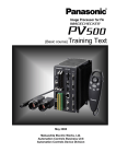
Machine Vision System
IMAGECHECKER PV200
High-spec Performance
in Ultra-compact Body
Please contact ..........
COMPACT & HIGH SPEC
Panasonic Electric Works SUNX Co., Ltd.
ULTRA HIGH SPEED VISION SYSTEM IMAGECHECKER PV200
2431-1 Ushiyama-cho, Kasugai-shi, Aichi, 486-0901, Japan
■Telephone: +81-568-33-7211 ■Facsimile: +81-568-33-2631
Overseas Marketing Department
■Telephone: +81-568-33-7861 ■Facsimile: +81-568-33-8591
panasonic-electric-works.net/sunx
All Rights Reserved ©Panasonic Electric Works SUNX Co., Ltd. 2011
No. CE-PV200-5 January, 2011
Spedfications are subject to change without notice.
Printed in Japan
2011.1
panasonic-electric-works.net/sunx
Panasonic Electric Works SUNX
COMPACT & HIGH SPEC
ULTRA HIGH SPEED VISION SYSTEM IMAGECHECKER PV200
Color/gray
combination
inspection
Geometry
Calculation
Smart edge
(Circle) / (Line)
P.04
P.06
P.06
Compatible
with 4M gray
camera
High accuracy
inspection
P.04
Screen
customization
Man-hour
reduction
P.07
Gray
preprocess
filters
P.08
PVWIN200
P.09
Improve inspection reliability
while reducing engineering man-hours
Image processing with top-level accuracy and performance in its class is available
with an unprecedentedly small number of man-hours required for programming.
The new ideal machine is a color/ gray combination type.
02
03
50 mm
1.969 in
Hardware
116.5 mm
4.587 in
Color and gray images can be simultaneously captured for inspection.
In addition, the “3+1” Quad Processor provides ultra-high speed parallel processing,
significantly reducing the inspection time.
148 mm
5.827 in
The features condensed into the ultra-compact body guarantee outstanding user-friendliness.
Camera selections
High
accuracy
inspection
DIN-rail
mountable
Five types of cameras, including a 4M gray camera, are compatible with the system.
You can choose color and/gray cameras according to the purposes of use.
new
"3 + 1" Quad-processor for high speed processing
Consists of a processor exclusively for image capture and transfer, a high-speed RISC-CPU, image-processing DSP, and a processor exclusively for display processing
■ Pipeline processing by the Quad Processor enables concurrent operation of the image capture process and inspection process.
■ Image transfer, image processing, inspection processing, calculation, and display processing operations can be carried out
asynchronously, achieving high speed processing.
■ DSP processing: The high-speed DSP as an engine dedicated to image processing perform gray preprocessing filtering in real time
■ Fan-less structure and high hardware reliability in standalone mode
Gray cameras
Color cameras
Quad-processor, DSP processing & pipeline processing
new
new
[Process comparison with our conventional model (PV310) ]
Dual Processor
[ 0.3M ]
[ 2M ]
[ 0.3M ]
[ 2M ]
Capture Inspection Calculation Display Transfer
[ 4M ]
32Bit
RISC
CPU
*The 4M camera cannot be used in
combination with another type of camera.
Two cameras, including a combination of color and gray cameras, can be simultaneously connected.
Capture Inspection Calculation Display Transfer
Output
Cannot start the next process unless
the present process is completed.
DSP
High definition color and gray cameras can be simultaneously connected. Inspections with color and gray images can be conducted concurrently.
Quad-Processor
Capture Inspection Calculation Display
DSP
Transfer
Custom
Color
Processor
Color images clearly
show red bad marks,
which are difficult to
detect with gray images.
Color/ gray combination
inspection system
Preprocess
Gray image
Gray preprocess
(Can be enabled/disabled)
Connector (gray edge)
Gray window
Flaw detection
Smart edge (circles)
Gray edge
Connector (binary window)
Smart edge (line)
Feature extraction
Connector (gray window)
etc.
The maximum, minimum, average, and deviation of RGB
values in an area can be obtained. The results can be used
for numerical calculations and externally output.
Evaluation criteria setting
Gray conversion
Color extraction
Color images can be converted into gray images by
specifying RGB values. This function makes it easier to find
foreign substances, raising the inspection accuracy.
Colors in different color phases can be simultaneously
extracted and inspected by using one inspection checker, which
was previously impossible with a conventional model (AX40).
04
Foreign Hair
substance
Foreign Hair
substance
Product B
Color image
Color extraction
Product C
Block 2
Product B
Direction check
Inspection 1
Block execution
0
Block 3
Product C
Direction check
Right
Left
Right
Left
Right
Left
Block 4
Product A
Right-direction check
Block 5
Product A
Left-direction check
Block 6
Product B
Right-direction check
Block 7
Product B
Block 8
Product C
Right-direction check
Block 9
Product C
OK
NG OK
NG OK
Up to ten different inspections can be executed immediately after a
trigger signal is input without spending time for product type switching
operations.
Trigger input
(Inspection block designation)
Block 0
Product type check
Block 1
Product A
Direction check
Color window
Gray conversion
Man-hour
reduction
Designated execution
Up to nine branches can be set to choose an inspection to
be executed depending on the test results.
Product A
The RGB value data can be used for color unevenness and other inspections.
Color image
Pipeline (parallel) processing by Quad-Processor
reduces the inspection time.
Branch execution
Color window
Available checkers
Smart matching
Transfer
Custom
Graphic
Processor
Gray preprocess
(Can be enabled/disabled)
Binary window
Capture Inspection Calculation Display
High-speed inspections are possible without a product type switching operation even if inspections to be executed should be switched due to
high-mix production or depending on conditions. The “branch execution” or “designated execution” options can be chosen for each product type
High
accuracy
inspection
Color
extraction
Gray preprocess
(Can be enabled/disabled)
Output
Branch execution/Designated execution
Color image
Gray
conversion
32Bit
RISC
CPU
Left-direction check
NG OK
NG OK
Left-direction check
NG OK
NG
OK
NG
Inspection 2
Block execution
1
OK
NG
Inspection 3
Block execution
2
OK
NG
Inspection 10
Block execution
9
OK
NG
The inspection results data of each block is held. The result
data can be used for other blocks, allowing you to customize
the inspection conditions according to the purpose of use by
operating multiple inspection blocks in optimum order.
High-speed communications and storage (Built-in memory / Ethernet / SD memory card)
Inspection result data output
■ Compatible with parallel I/O , RS232C (115.2 kHz), Ethernet (Gigabit). The RS232C PLC communications are now compatible with Modbus RTU. new
Image data
■ Up to 312 images captured by the 0.3M camera, 39 images captured by the 2M camera and
14 images captured by the 4M camera can be stored in the built-in memory in real time
(without increasing the processing time).*1
■ A 32 GB SD memory card can store a maximum of about 90,000 images captured by the 0.3M camera,
about 16,500 images captured by the 2M camera or about 7,600 images captured by 4M camera. *2
■ The Gigabit Ethernet LAN port allows image transfers at three to five
PV310
Transfer
times the speed of 100-Megabit Ethernet. Via this port, one image
100-Megabit Ethernet
captured by the 0.3M camera can be transferred in 80 msec.*3
PV200
*1: When one camera is connected. *2: Color camera images: Bayer format
Transfer
*3 Depends on the connected equipment.
Gigabit Ethernet
05
High Inspection Reliability and Small Number of Engineering Man-Hours
Smart Edge function accurately detects circles and lines without complicated area settings or numerical calculation programming.
The character/figure drawing and data R (Read)/W (Write) functions accurately communicate the inspection status with high viewability.
These features improve the operability at production sites where there are many restrictions to enhance the reliability and
productivity while significantly reducing engineering man-hours.
Smart Edge (Circle)/(Line)
High
accuracy
inspection
Screen customization
Man-hour
reduction
Complicated inspection processes can be easily operated through high accuracy measurements.
A function for accurate approximation of circles/lines
This function detects a maximum of 3,000 edge points for a line and 3,600 for a circle in one area, dramatically improving the accuracy
of the measurement of dimensions and positions. This function has also significantly reduced the man-hours required for setting.
Man-hour
reduction
PV200 has been designed by pursuing high productivity, work efficiency, and user friendliness at all stages from the image
processor introduction evaluation through operation for full-scale production after introduction to reduce the operation time
and burden on users, and to support the display of appropriate inspection information.
1. A Gray Scale Edge scanning area is created, and edge points in the area are searched to detect the contour of the object.
Operation
principle
2. Virtual circles and approximate straight lines can be identified with a high degree of accuracy based on the target edge points.
3. Pass (OK) /fail (NG) evaluations are made based on the measured values (radius, diameter, and width), deviations, circularity,
straightness, and the number of edges outside the area.
Unit conversion axes
Operation customization
by external signal
X and Y axes indicate
the scale converted
into the actual
dimensions.
(Separately settable
for each camera)
Smart Edge (circle) setting example
The center of the virtual circle,
radius, diameter, circularity, and
ring width can be measured.
One cell can have a minimum width of one pixel
(linear scanning), and a maximum of 3,600 cells
can be set per 0.1°.
The unit is equipped
with a total of five
points for ASSIGN
and EXTRA signals,
which allow you to
customize the
allocations of tasks,
such as image data
output and screenshot
printing.
The center and radius of the
corner are measured.
Customizable Display
There are cases where tuning of the inspection area, preprocessing
parameters, etc. is required even after finalizing a program. Such minor
modifications can be quickly made in RUN mode without replacing the
program or moving to the setting screen (80 items/page, up to two pages).
In combination with PVWIN200 setup software, any text data can be
indicated (four languages and five fonts).
A function for drawing text (multi-lingual), measured values,
cross marks, arrow marks (dimension lines), rectangles, and
ellipses. This function allows drawn items to be displayed
following the calculation results or detected positions, and it
is possible to specify the character size and fill regions. It is
also possible to switch the drawn item colors or turn on/off
the display of the items according to the pass/fail check
results so that users can get inspection results more easily.
[Modification examples]
The influence of chippings
and burrs is eliminated to
accurately detect the target
straight line by approximation.
A maximum of 3,000 cells can be set.
Geometry Calculation
Irregular
part
High
accuracy
inspection
The width, chipping, and
straightness of a strip-shaped object
are measured, and the maximum
and minimum values are obtained.
NG
Change the X coordinate of the start point.
Man-hour
reduction
Virtual Circle
Distances, intersections, and median lines can be detected.
Approximate
Straight Line
Intersection of
Two Lines
This function detects the distance between two points, the
intersection of two lines, the median line of two lines, the perpendicular distance, and an approximate ellipse. In combination with
Smart Edge (circle) / (line), this function recognizes the object as a
geometric figure, allowing the coordinates, distances, dimensions,
and angles to be obtained without preparing calculation formulas.
Change the pre-processing filter setting.
400%
06
98.864
99.045
99.783
Layout
100%
2%
[Burr height measurement]
98.289
Check: NG
Image displays can be zoomed in the 2 to 400% range.
[Intersection coordinate/angle measurement]
98.567
Burr/Chipping
Zoom
Versatile
application
new
Data R (Read) / W (Write) function
Smart Edge (line) setting example
The VGA screen (640 x 480 pixels) can display
a maximum of two images and two pages of the
Data R/W screen. Screens and data R/W field
layouts can be customized. Up to 16 patterns
can be registered. The information displayed can
be switched according to the status by using an
external signal as well as the keypad.
[Angle/perpendicular distance measurement] [Warpage height measurement]
07
High Performance and Simple Setting Procedures
The gray preprocess filters minimize the influence of variations in the lighting or object conditions, allowing for more
accurate and reliable appearance inspections.
A variety of utility functions are available for simple, stress-free, and easy setting work.
Gray preprocess filters
High
accuracy
inspection
Utility
Man-hour
reduction
21 types of gray preprocess filters are available. Reliable inspections are possible even under non-uniform lighting conditions or in
the case of images with noise.
● Preprocess filters: 21 types ● Preprocess groups: A maximum of 16 groups/camera ● Preprocess steps: A maximum of 10 steps/group
Main purpose
Main purpose
Filter name
● Tophat
Flaw detection
● Dynamic
● Frequency
Noise removal
Rotating and
flipping
Contour
enhancement
Extraction
● Dilation
● Erosion
● Erosion
● Dilation
→ Dilation
→ Erosion
Blurring
Gray scale
changing
● Rotation
● Reflect
Filter name
● Sobel
● Edge
Extraction X
● Edge Extraction Y
● Sharpen
● Prewitt
● Laplacian
Man-hour
reduction
Checker list
Collective moving of inspection areas
The checker list shows the on/off state of each inspection
function and the inspection results so that users can check
the program outline. It is possible to jump to the setting
screen for a selected function and edit the settings.
Check on the checker list
Jump to the checker setting screen
● Median
● Smoothing
● Auto
● Gray
Correction
Cut
This function is essential
to simultaneously move
multiple inspection areas
for the purpose of fine
adjustment of the target
position. The areas can
be chosen by camera,
position correction group,
or inspection checker
type.
Choose
and jump
● Area
Averaging
settings
● Correction
Collective
moving
Setting help
Histogram
In the image preprocessing and the binarization setting
screens, both the original image and its histogram are
displayed as guidance for processing
Setting help
function
Focus adjustment
Communication test
Aperture adjustment
Parallel I/O test
Gray data analysis
Thumbnail of the original image
Application example
Checking container
lids for adhesion of
foreign substances
Original image
Processed image
Filter used
Splash screen
The splash (startup) screen can be changed to an original
screen, such as a screen suitable for the user's equipment
or a screen including a brand logo. (A bitmap with a
maximum size of 640 x 480 pixels)
Tophat
Marker function
Checking films/sheets
for scratches/wrinkles
A straight line, rectangle, circle, ellipse, and cross line can
be displayed at any position. The display position can be
specified by using external signal.
Frequency Extraction
Area Averaging
new
Result output
After processing
Detecting dirt on
transparent sheets
Dynamic
Extracting printed
characters (deleting
the background)
Dynamic
Before processing
Password protection
The operation for switching to the setting screen can be
password-protected to prevent incorrect settings due to an
unintended keypad operation. The password can have a
maximum of 15 digits (from 84 alphanumeric and symbol
characters).
PVWIN200 setup software
Man-hour
reduction
User-friendly drag-and-drop operations
Checking the inside of
containers for adhesion
of foreign substances
Frequency Extraction
Tophat
Judgement results and numeric result data can be
simultaneously output through the RS232C and Ethernet
port and to an SDHC card. For example, inspection result
data can be output to a PLC for machine control purposes
while saving the same data on an SD memory card.
Simulation cycle for debugging
Drag the target image and drop it onto a PVWIN200 screen
to start the operation. The guidance by the navigation view
icons will help you set the inspection conditions.
The continuous simulation and data logging functions
facilitate setting data corrections and verifications. The
export function allows you to manage the setting data
change history.
1
Simulation
cycle
Checking sintered
parts for breaks/
cracks
2
Can be switched to the screen
displaying "NG" items only
Frequency Extraction
Tophat
PV200 Setup Software
Download PVWIN for free from:
http://panasonic-electric-works.net/sunx
08
09
Fulfilling Basic Functions
This model also features the existing model’s gray-scale and binary inspection functions. The sufficient capacity allows
for storage of up to 25,600 types of inspection function settings (with an SD memory card inserted) and up to 1,000 checkers
(per product type) to be ready for inspections of many items or points. This level of capacity will also enable the future
expansion of the inspection scope.
Connector checker
High
accuracy
inspection
Matching
Man-hour
reduction
PV200 features three types of checkers exclusively designed for connector inspections, which was previously very time-consuming,
requiring only one area to be prepared. These checkers make it easier to add product types and modify settings, and significantly
reduce the required number of man-hours.
Pin pitch inspection
Inspection example
High
accuracy
inspection
Low contrast matching
360° rotation search
Reliable detection is possible even if the object image has a
low contrast (the contrast between the background and the
object (work piece) is low) or if the object is chipped.
This function measures the distance between
the edges of each pair of adjacent pins and
evaluates the results based on the preset upper
and lower limits. Data of the “start point”, “end
point”, and “number of pins” should be input.
Detects low-contrast images
Detects partly chipped marks
Black/white inversion
Even negative images can be detected.
The matching function has
been upgraded. Even if object
positions are rotated up to
360°, they can be inspected.
Even if objects are roughly
positioned, a high-precision
inspection is possible.
Difference detection
Based on the position information obtained by the matching
function, the registered object and detected object are
overlapped and compared on a pixel-by-pixel basis. Any pixels
with a difference in brightness over a certain level are
detected. The area value of such pixels can then be used to
make pass/fail evaluations.
Template
Inside pin gap inspection
This function inspects the gap between facing
ends of pins. Simply input the number of pins,
and the data will be attached. The upper and
lower limits of the gap can be set.
Pin coplanarity inspection
This function detects raised pins. In the same
way as the pin pitch inspection, adjust the
position using one checker and input the
number of pins, and the data will be attached.
Then simply input the threshold.
Multiple template search
A high-precision inspection is possible by searching a
maximum of 64 templates in the same search area to detect
a result with the highest correlation.
High
accuracy
inspection
Detected by matching
Template
0
Template
1
Template
2
Template
3
Template
4
Detects different portions only
Common template registration
Template images
Object of search
Flaw detection
Difference detection result
Common templates of alignment marks can be shared. The
same template can be used for all product types, preventing
variations in the inspection accuracy among different
product types. Duplication of registration can be avoided,
saving on the total memory space. Individual registration by
product type is also available.
After searching all templates,
Template 2 with the highest
correlation is used for detection.
Man-hour
reduction
This function is ideal for appearance inspections for scratches, stains, chipped edges, burrs, and other flaws in objects, which are
indispensable elements of in-process inspections.
The inspection is carried out based on the gray scale comparison with neighboring parts, even enabling the detection of minor
scratches, stains, and chipping.
Scanning conditions
The micro cell area (a minimum of 3x3 pixels) is continuously generated, and defects
are detected based on the amount of change in the density in the inspection area.
[Line]
[Circles, Ellipses, and Partial arcs]
Inspections of a variety of points of a variety of products
■Data for up to 256 types can be saved in the built-in memory alone, and 25,600 with an SD memory card inserted.
■Maximum registrable number of checkers: 1,000 checkers/type
[Checker types]
Line, binary window, gray window, binary edge, gray edge, feature extraction, smart matching, flaw detection, three connectors
(binary window, gray window, and gray edge), smart edge (circles)/(line) and geometry calculation --- A total of 14 types
256 cells max.
■Maximum registrable number of numerical computation expressions: 1,000 expressions/type
[Plane]
0.1°
Chipping and burrs
pitches min.
256 cells
A variety of operators for numerical computation are available: Four fundamental operations (+, -, x, ÷), bracket operation,
trigonometric function (14 types), comparison function (6 types), mathematical function (15 types), geometric function (18 types),
and statistical function (18 types)
■Binary level groups: 16 groups/type per camera
■Execution blocks: 10 blocks/type
Chipping and burrs
10
256 cells
65,536 cells max.
■Position adjustment: 1,000 checkers/type Area adjustment: 1,000 checkers/type
3,600 cells max.
* Minimum size of one cell: 3x3 pixels
11
System Configuration
Dimensional Drawing
Controller units/Monitors/Cameras/Keypads
Equipped with a full selection of interfaces
essential for image processing devices of
the future
Controller unit ANPV0202ADP
USB2.0
116.5
4.587
*The 4M camera cannot be used in
combination with another type of camera.
(16.5)
(0.650)
Model Numbers
2M color and gray cameras
4M gray camera
ANPVC2260•ANPVC1210
ANPVC1470
29
1.142
(57.3)
(2.256)
12
38
0.472
1.496
Controller units/Cameras/Keypads/Monitors
0.3M color camera
(Quad-speed)
Camera cables
for PV200
31.3
1.232
(7.3)
(0.287)
20
0.787
3 m type:
3 m type:
3 m type:
5 m type:
5 m type:
10 m type:
10 m type:
10 m type:
ANPVC8103
ANPVC1210
4M gray camera
ANPVC1470
ANPVP03
ANPVC8105
ANPVP10
ANPVC8110
15
0.591
32.7
1.287
15
0.591
32.7
1.287
Operation keypad ANPVP**
48 1.890
ANPVC8110R
145
5.709
ANB845NL
ANM88161
f=25 with lock
ANB846NL
f=25 with lock
ANM88251
f=50 with lock
ANB847L
Adapter rings
(for the 0.3M cameras and 2-megapixel cameras)
XGA monitors
0.3M camera lenses
f=8.5
ANB843L
F-number
1.2
1.5
1.4
1.4
1.4
1.6
1.4
2.8
1.4
1.4
2.8
ØA
42 1.654
42 1.654
31 1.220
30.5 1.201
31 1.220
30.5 1.201
48 1.890
30.5 1.201
34 1.339
34 1.339
34 1.339
L
46 1.811
1
– *
40 1.575
1
– *
33 1.299 31.21 1.229 37.3 1.469 31.5 1.240 48 1.890
1
1
1
– *
– *
– *
21
21 0.827
1
1
1
– *
– *
– *
19.8
20.05 0.789
38.5 1.516
C
1
– *
1
– *
Monitor cables
L
(20) (34)
ANPVL162
f=25
ANPVL252
f=50
ANPVL502
5 mm x 1 ring
ANB84805
LED lighting equipment for image processing
Digital power supply units for LED lighting
40, 20, 10, 5, 1, 0.5 mm x 1 ring
ANB848
10.4 inches
ANPVM11021
ANMX83313
5 m type:
ANMX83315
ANB86001
12
30W
ANB86003
20.6 0.811
Lens
38 1.496
52.2 2.055 77.5 3.051
22.5 0.886 22.5 0.886 22.5 0.886
22 0.866
22 0.866
22 0.866
*1 The projection of the lock screw (M1.4
M0.055 pan-head machine screw) is a
maximum of 2 mm 0.079 in.
Camera
L
(Ø4.8)
(Ø0.189)
Focus lock screw
(0.787) (1.339)
LED lighting equipment for image processing
Digital power supply units for LED lighting
ANB86001
90
3.543
ANB86003
140
5.512
60
2.362
10W
21 0.827
Aperture lock screw
(43)
(1.693)
f=16
2-megapixel camera lenses
f=16
f=25
f=50
f=16
f=25
f=50
ANB845NL ANM88161 ANB846NL ANM88251 ANB847NL ANM88501 ANPVL162 ANPVL252 ANPVL502
ANM88501
3 m type:
Bottom view
(without the insulating base)
C
2-megapixel camera lenses
10
0.394
Lenses for camera
B
f=50 with lock
2-M3 M0.118
(Depth 3 0.118)
34
2-M2 M0.079
1.339
(Depth 3 0.118)
25
0.984
21
0.827
B
ANB843L
f=16 with lock
10
0.394
1/4″–20UNC
Top view
(Depth 9 0.354)
(without the insulating base)
0.3M camera lenses
f=16 with lock
Insulating
base
3
0.118
ANPVC8103R
ANPVC8105R
34
1.339
10
0.394 27.5
2-M4 M0.157
1.083
(Depth 7 0.276)
10 10
2-M2 M0.079
0.394 0.394
(Depth 3 0.118)
25
0.984
2-M3 2-M0.118
(Depth 7 0.276)
(6.3)
(0.248)
44
1.732
(54)
(2.126)
10
2-M3 M0.118
(Depth 3 0.118) 0.394
f=6
ANB842NL
f=8.5 with lock
4-M4
4-M0.157
53
2.087
44
1.732
2×4-M3
2×4-M0.118
(Depth 3 0.118)
2×4-M3 2×4-M0.118 (Depth 3 0.118)
(53.3)
(2.098)
40.5
1.594
6.5
0.256
44
1.732
(7.3)
(0.287)
14
0.551
ANPVC2260
2M gray camera
1/4-20UNC (Depth 9 0.354)
Flexible
camera cables
2M color camera
ANPVC2040
ANB842NL
(57.3)
(2.256)
38
12
1.496
0.472
14
0.551
10
0.394
f=6 with lock
192
7.559
75
2.953
(11)
(0.433)
(39)
(1.535)
Keypads
75
2.953
(16)
(0.630)
0.3M color and gray cameras
29
1.142
Digital cameras for PV200
140 5.512
ANPVC2040•ANPVC1040
VGA monitor output
ANPVC1040
200
7.874
50
1.969
ØA
Parallel I/O
ANPV0202ADP
157.8 6.213
(LCD screen area)
210.4 8.283
(LCD screen area)
0.3M gray camera
2M gray camera
4M gray camera
257
10.118
43 (11)
(16)
4 1.693 (0.433)
(0.630)
0.157
0.3M color camera
2M color camera
Serial (RS232C)
[2-camera type]
265.0
10.433
148
5.827
Cameras (Digital cameras)
Up to two cameras of two different types can be connected.
Keypad
0.3M gray camera
(Quad-speed)
XGA monitor ANPVM11021
Giga bit Ethernet connector
SD memory card
(SDHC compatible)
PV200 IMAGECHECKER
units
(Unit: mm in)
62
2.441
170
6.693
90
3.543
110
4.331
15
9.5 0.591
0.374
140
5.552
13
Specifications
Specifications
General specifications
Image processing functional specifications
Item
Item
Rated operating voltage 24V DC
Camera Specifications
Specifications
Item
Specifications
Preprocessing selections: Gray conversion / Color extraction / Gray preprocessing
Type/Mode No.
4M gray/ANPVC1470
2M gray/ANPVC1210
0.3M gray/ANPVC1040
2M color/ANPVC2260
0.3M color/ANPVC2040
Inter line method
Inter line method
Inter line method
Inter line method
Inter line method
2/3-inch CCD fixed image element
1/1.8-inch CCD fixed image element
1/3-inch CCD fixed image element
1/1.8-inch CCD fixed image element
1/3-inch CCD fixed image element
2048 horizontal x 2048 vertical pixels
1600 horizontal x 1200 vertical pixels
640 horizontal x 480 vertical pixels
1600 horizontal x 1200 vertical pixels
640 horizontal x 480 vertical pixels
Pixel size: 3.45 μm x 3.45 μm
Pixel size: 4.4 μm x 4.4 μm
Pixel size: 7.4 μm x 7.4 μm
Pixel size: 4.4 μm x 4.4 μm
Pixel size: 7.4 μm x 7.4 μm
(Square pixels)
(Square pixels)
(Square pixels)
(Square pixels)
(Square pixels)
30 flams/sec max.
120 flams/sec max.
30 flams/sec max.
120 flams/sec max.
0 to +45°C 32 to +113°F
0 to +40°C 32 to +104°F
0 to +45°C 32 to +113°F
Operating voltage range 21.6 to 26.4 V DC (including ripples)
Available only when a color camera is connected. For each product type, 16 groups/camera
Rated current consumption 1.2 A max.
Gray conversion Each R/G/B value setting for gray conversion can be changed within the range
Ambient temperature during use 0 to +45°C 32 to +113°F (no freezing or condensation)
of -1,000 to 1,000.
Storage ambient temperature -20 to +60°C -4 to +140°C (no freezing or condensation)
Available only when a color camera is connected. Color extraction mode: Selectable between high speed and expansion
Ambient humidity during use 35 to 85%RH (at 25°C 77°F, no freezing or condensation)
Number of extractable colors
Storage ambient humidity 35 to 85%RH (at 25°C 77°F, no freezing or condensation)
Color extraction
Capture element
Pixels
High speed: A total of 16 colors when one camera is connected and eight colors when two cameras are connected.
Frame rate
16 flams/sec max.
Expansion: A total of 128 colors when one camera is connected and 64 colors when two cameras are connected.
Lens mount
C mount
Noise immunity
1,000 V, Pulse width: 50 ns, 1 μs (using the noise simulator method)
Vibration resistance
10 to 55 Hz, 1 sweep/min, double amplitude of 0.75 mm 0.030 in, 30 minutes each in the X, Y, and Z directions
Only eight registered colors can be selected from one checker.
Ambient temperature during use *5 0 to +40°C 32 to +104°F
Shock resistance
196 m/s2, 5 times each in the X, Y and Z directions
For each product type, 16 groups/camera, 10 stages max.
Ambient humidity during use
Preprocessing filters: 21 types
Vibration resistance
(Dilation, Erosion, Erosion → Dilation, Dilation → Erosion, Auto correction,
Shock resistance
490.3 m/s2, 1 time each in the X, Y and Z directions
Gray cut, Area averaging, Correction settings, Median, Smoothing, Sobel,
Weight (Excluding the lens)
110g approx.
Prewitt, Laplacian, Edge extraction X, Edge extraction Y, Sharpen, Tophat,
*5 No freezing or condensation
Preprocess filters
100 MΩ or higher (measured by a 500 V DC megger) *1
(initial value)
Input and output terminals -- Non-energized metal part
Gray preprocessing
Power terminal -- Non-energized metal part
500 V AC for 1 min (600 V AC for 1 sec), Cutoff current: 10 mA *1
Input and output terminals -- Power and ground terminals
1,000 formulae/product type max., including those for evaluation result output (depends on setting data)
(initial value)
Input and output terminals -- Non-energized metal part
Calculations involving output values of inspection functions
Power terminal -- Non-energized metal part
Operators
Battery life
10 years approx. (at 25°C 77°F)
Weight
0.5 kg approx. (incl. terminal blocks)
Numerical
Pollution degree
Pollution degree 2
calculation
Statistic data operation items
CPU
32-bit, RISC CPU & DSP
Other operation items
Cameras
color cameras can be connected.
Input/output
VGA (640x480) output
Memory card
SD/SDHC memory card
Models compatible with RS232C (three-wire) x 1 Modbus RTU and the PLC link function
Panasonic Electric Works SUNX: FP Series
Serial
Operators
Judgement
Parallel
14 inputs / 15 outputs
Keypad input
1 connector for dedicated keypad (ANPVP**) MIL terminals: 32 inputs / 32 outputs
USB
USB 2.0, A-B type (Only PVWIN200)
Ether net x 1, PLCs compatible with the PLC link function
Ethernet
Panasonic Electric Works SUNX: FP series ET-LAN unit
Mitsubishi Electric: Q series Ethernet unit
*2 The 4M gray camera cannot be used in combination with another type of camera.
Image processing functional specifications
Item
Specifications
Menu display
Eight languages (nine fonts), Switchable (Japanese, English, Korean, Traditional Chinese and Simplified Chinese)
Others
outputs from OUT0 to OUT15, or all setting output)
Group move
Specify the “Move” or “Not move” option for each checker type.
Position and rotation adjustment checkers cannot be moved.
Shapes
Data R/W
Others
Comment input
Position
Set position/Adjusted position
settings
Display
Yes/No
Normal execution
Execution of all checkers
Execution mode Branch execution
Designated execution
Inspection start instruction
Re-inspection start instruction
Product type change instruction
Template re-registration instruction
Display layout switch instruction
Gray scale processing/thresholding processin/Color extraction/gray conversion
Operation/stop switch instruction
Statistics reset instruction
0.3M camera (gray/color): 640 horizontal x 480 vertical pixels
Error reset instruction
Capture method
Instruction to save setting data in the built-in memory
Select from: All cameras or detection trigger
Frame shooting only. Capable of partial capture of one point
In partial capture mode, the minimum capture area to be set for the 0.3M/4M camera is
one line, and that for the 2M camera is 100 lines.
(The area can be set in increments of one line for the gray camera, and two lines for the color camera.)
Shutter speed
30 μs to 1000 ms (Set in increments of 10 μs)
Gain setting range
1.0 to 5.0
No. of product types
25,600 types max. (depends on setting data)
Input
Instruction to save setting data in the SD memory card
Instruction to erase the image memory
Instruction to print the screenshot
Inspection/processing cancellation display
Instruction to save the latest inspection image
Instruction to read/change the set value
Instruction to prohibit the keypad screen operation
Keypad emulation instruction
Inspection functions (Checkers) Position adjustment, Position/rotation adjustment, Rotation adjustment area size adjustment binary window, Gray
Computer link
window, Binary edge, Gray edge, Feature extraction, Smart matching, Line, Flaw detection, Connector (binary
Scanning operation count
window), Connector (gray window), Connector (gray edge), Smart edge (circles), Smart edge (line), Color window
two lines, perpendicular distance, approximate straight line, approximate circle, and approximate ellipse)
Character/Figure Drawing
Up to 10,000 characters/graphics (1,000 checkers x 10)/product type can be displayed
on the images (depends on setting data).
Sequential processing: After completing the result output, the next image capture for inspection can be started.
Inspection operation mode Parallel processing: After the capture and the synchronized output of results of the previous inspection are completed, the image
capture process for the next inspection is ready to start, and then the capture and inspection results output are processed concurrently.
Slice level group
16 group/camera, 256-gray scale (0 to 255)
Overall judgement output
Output
Seven calculation functions (distance between two points, intersection of two lines, median lines of
Instruction to read setting data from the SD memory card
Instruction to save the image memory in the SD memory card
character/figure drawing (depends on setting data)
Geometry Calculation
Instruction to read setting data from the built-in memory
Instruction to cancel the saving/reading of setting data
1,000 checkers/product type max., including those for geometric calculation and
1,000 checkers/product type max., including those for inspection functions and character/figure drawing (depends on setting data)
Blocks to be executed (0 to 9) can be set.
○: Applicable, ×: Inapplicable
Display effects: Gray Scale/Thresholding Group/Pre-processing Group/Color/Extraction
Connection by Power Over Camera Link (PoCL)
Destination blocks (0 to 9) can be set.
Judgement calculation (JD) result output
Numerical calculation result output
Image output
Screenshot output
Parallel
Serial
○
○
○
○
○
○
○
○
○
○
○
○
○
○
○
○
○
○
×
×
×
×
○
○
○
○
×
×
○
○
○
○
○
○
○
○
○
○
○
○
○
○
○
○
○
×
○
○
○
○
○
○
○
○
×
×
Ethernet
○
○
○
○
○
○
○
○
○
○
○
○
○
○
○
○
○
×
○
○
○
×
○
○
○
○
○ *4
○ *4
SD memory
card
–
–
–
–
–
–
–
–
–
–
–
–
–
–
–
–
–
–
–
–
–
–
○
○
○
○
○
○
*3 Image and screenshot output functions via Ethernet are received by dedicated software, Image Receiver for PV.
t0.5
t0.5
t1
t0.5 t0.5
t1.5
t1
t2
t0.5
t0.5
t0.5
t2
t1.5
t0.5
t1
t0.5
t2
t2
t1
t0.5
t5.5
t2
t1.5
t1
t8.5
t1.5
t2
t2
t11.5
t5.5
t2
t14
t7
t2
10 t5.5
t17.5
t8.5
t23.5
t11.5
t35.5
Value t indicates the adapter
t17.5
t44
ring thickness (mm).
t59
t88.5
2
100
1,000
4M gray camera
500
t1
t4
t3
t2.5
2
30
t3.5
t2.5
t12
t17.5
t9
t23.5
t12
t28.5
t35.5
t47
t70.5
t88.5
t118
t176.5
t6
10
t4.5
t1
t1
ANB845NL
(f16mm)
ANB846NL
(f25mm)
ANMM88501
(f50mm)
7,000
t0
t0.5
t1.5
new
and gray camera
500
t0
t0.5 ANPVL162
(f16mm)
t0.5
t1
t0.5
t1
t0.5
t1.5
t0.5
ANPVL252
t1
t1.0
t2
(f25mm)
t1.5
t2
t1.5
t2
t5
t2
ANPVL502
t2
t6.5
t2
(f50mm)
t8.5
t2
t13
t6.5
t17.5
t8.5
t21
t10.5
t26
t13
t35
Value t indicates the adapter
t52.5
t66
ring thickness (mm).
t88
t132
t0.5
100
10
2
WD [mm]
t0
30
100
1,000
5,000 WD [mm]
new
ANPVC1470
100
ANB842NL
(f6mm)
ANB843L
(f8.5mm)
t0.5
30
Coordinates, coordinate origin, horizontal and vertical coefficients can be set for each camera to obtain actual dimensions.
Template
External input/output functions
Camera connection
Rectangle/Circle, Ellipse/Polygon/Line/Cross
t0
t0
t0
t0
100
Substitution of title input, checker conditions/results, numerical calculation results, numerical calculation judgment results,
Conversion data
2M color
ANPVC2260•ANPVC1210
t0
judgment results, statistical results possible. Change of upper/lower limits of numerical computation in the table in RUN mode possible.
Image display: Through/Memory/NG object images
Number of connected cameras Up to two cameras
65g approx.
65g approx.
and gray camera
new
500
Two-window display of up to 80 (5x16) cells/product type on screen in table form in RUN mode
4M camera (gray): 2048 horizontal x 2048 vertical pixels
Trigger input
65g approx.
ANPVC2040•ANPVC1040
8 markers/product type max. for each camera, Graphic display on the operation screen, Selectable from six colors
Marker
2M camera (gray/color): 1600 horizontal x 1200 vertical pixels
Processing resolution
conditions, parallel output setting (8 outputs from OUT0 to OUT7 and 16
Collective movement of set checkers in units of position/rotation adjustment groups
and binary/Display area (640 x 480)
Processing methods
NOT/AND/OR/XOR/Brackets
Total judgment conditions, save image conditions, Image output
Split-screen display of up to two camera images, Zoom function (2 to 400%)
Monitor display (VGA)
Previous data of numerical calculation and judgment results, general-purpose registers
Number of substitution items 16 items/formula
Allen-Bradley: SLC500
Fuji Electric: MICREX-SX SPH series
0.3M color
NG average/NG variance/NG judgment max./NG judgment min./NG range
Substitution for and logical calculation of evaluation results from checkers and numerical computations
Mitsubishi Electric: A, Q, FX (FX1N), and FX-2N series (FX2N, FX3U, and FX3UC)
OMRON: C, CV, and CS1 series
700 m/s2, 3 times each in the X, Y and Z directions
65g approx.
Visual fields
OK average/OK variance/OK judgment max./OK judgment min./OK range/
1,000 formula/product type max., including those for numerical calculation (depends on setting data)
Up to two 4M gray cameras can be connected.
Monitor output
comparison functions (6 types), math functions (15 types), geometric functions (18 types)
Number of reference operators 16 items/formula
Up to two cameras selected from among 0.3M (640 x 480) and
2M (1600 x 1200) gray and
Four fundamental operations (+, -, x, ÷), bracket operations, trigonometric functions (14 types),
User limit: 1000 items /product type max.
Functional specifications
Specifications
10 to 55 Hz, 1 sweep/min, double amplitude of 0.75 mm, 30 minutes each in the X, Y, and Z directions
Scan count/OK count/NG count/Average/Variance/Max./Min./Range/
*1 The evaluation was carried out with the primary side power supply varistor and capacitor removed from the internal circuit of the unit.
Item
35 to 85%RH (at 25°C (no freezing or condensation)
Dynamic, Gray difference, Rotation, and Reflect)
Breakdown voltage
Y-direction (vertical) visual field [mm]
Input and output terminals -- Power and ground terminals
Y-direction (vertical) visual field [mm]
Insulation resistance
0 to +40°C 32 to +104°F
Y-direction (vertical) visual field [mm]
Specifications
t2
t9
t0.5
t0.5
t1
t3.5
t2
t2.5
t1.5
t1
ANPVL162
(f16mm)
ANPVL252
(f25mm)
t4.5
ANPVL502
(f50mm)
t7
Value t indicates the adapter
ring thickness (mm).
100
Customized LED light sources
1,000
5,000 WD [mm]
The X-direction (horizontal) visual field is the Y-direction visual field multiplied by 1.3.
* Please use these values as reference purposes only. Check the details with the
PV200 User’s Manual.
Single unit series
Line unit series
24 V DC type
NTN Series
The brightness, shape, number of
lamps, and installation method can
be customized to fit purposes of use.
Connection with ANB86001 or
ANB86003 LED lighting power supply
enables continuous lighting.
These LED light sources can be used
only with 24 V DC.
Do not use with any other power
voltage.
Single unit
Wide angle: NTN141
Diffusion: NTN142
(External dimensions of the unit:
80 mm x 50 mm 3.150 in x 1.969 in)
2-lamp type
Wide angle: NTN138
Diffusion: NTN139
(External dimensions:
180 mm x 44 mm 7.087 in x 1.732 in)
4-lamp type
Wide angle: NTN136
Diffusion: NTN137
(External dimensions:
280 mm x 44 mm 7.087 in x 1.732 in)
Customization
examples
Contact for inquiries about NTN series
customizable LED light sources
Plane type
Linear type
Frame type
New Business Promotion Department, Lighting Manufacturing Business Unit, Panasonic Electric Works Co., Ltd.
Address: 1048 Kadoma, Kadoma-city, Osaka 571-8686, Japan Tel: +81-6-6909-5734
14
15
Specifications
Specifications
General specifications
Image processing functional specifications
Item
Item
Rated operating voltage 24V DC
Camera Specifications
Specifications
Item
Specifications
Preprocessing selections: Gray conversion / Color extraction / Gray preprocessing
Type/Mode No.
4M gray/ANPVC1470
2M gray/ANPVC1210
0.3M gray/ANPVC1040
2M color/ANPVC2260
0.3M color/ANPVC2040
Inter line method
Inter line method
Inter line method
Inter line method
Inter line method
2/3-inch CCD fixed image element
1/1.8-inch CCD fixed image element
1/3-inch CCD fixed image element
1/1.8-inch CCD fixed image element
1/3-inch CCD fixed image element
2048 horizontal x 2048 vertical pixels
1600 horizontal x 1200 vertical pixels
640 horizontal x 480 vertical pixels
1600 horizontal x 1200 vertical pixels
640 horizontal x 480 vertical pixels
Pixel size: 3.45 μm x 3.45 μm
Pixel size: 4.4 μm x 4.4 μm
Pixel size: 7.4 μm x 7.4 μm
Pixel size: 4.4 μm x 4.4 μm
Pixel size: 7.4 μm x 7.4 μm
(Square pixels)
(Square pixels)
(Square pixels)
(Square pixels)
(Square pixels)
30 flams/sec max.
120 flams/sec max.
30 flams/sec max.
120 flams/sec max.
0 to +45°C 32 to +113°F
0 to +40°C 32 to +104°F
0 to +45°C 32 to +113°F
Operating voltage range 21.6 to 26.4 V DC (including ripples)
Available only when a color camera is connected. For each product type, 16 groups/camera
Rated current consumption 1.2 A max.
Gray conversion Each R/G/B value setting for gray conversion can be changed within the range
Ambient temperature during use 0 to +45°C 32 to +113°F (no freezing or condensation)
of -1,000 to 1,000.
Storage ambient temperature -20 to +60°C -4 to +140°C (no freezing or condensation)
Available only when a color camera is connected. Color extraction mode: Selectable between high speed and expansion
Ambient humidity during use 35 to 85%RH (at 25°C 77°F, no freezing or condensation)
Number of extractable colors
Storage ambient humidity 35 to 85%RH (at 25°C 77°F, no freezing or condensation)
Color extraction
Capture element
Pixels
High speed: A total of 16 colors when one camera is connected and eight colors when two cameras are connected.
Frame rate
16 flams/sec max.
Expansion: A total of 128 colors when one camera is connected and 64 colors when two cameras are connected.
Lens mount
C mount
Noise immunity
1,000 V, Pulse width: 50 ns, 1 μs (using the noise simulator method)
Vibration resistance
10 to 55 Hz, 1 sweep/min, double amplitude of 0.75 mm 0.030 in, 30 minutes each in the X, Y, and Z directions
Only eight registered colors can be selected from one checker.
Ambient temperature during use *5 0 to +40°C 32 to +104°F
Shock resistance
196 m/s2, 5 times each in the X, Y and Z directions
For each product type, 16 groups/camera, 10 stages max.
Ambient humidity during use
Preprocessing filters: 21 types
Vibration resistance
(Dilation, Erosion, Erosion → Dilation, Dilation → Erosion, Auto correction,
Shock resistance
490.3 m/s2, 1 time each in the X, Y and Z directions
Gray cut, Area averaging, Correction settings, Median, Smoothing, Sobel,
Weight (Excluding the lens)
110g approx.
Prewitt, Laplacian, Edge extraction X, Edge extraction Y, Sharpen, Tophat,
*5 No freezing or condensation
Preprocess filters
100 MΩ or higher (measured by a 500 V DC megger) *1
(initial value)
Input and output terminals -- Non-energized metal part
Gray preprocessing
Power terminal -- Non-energized metal part
500 V AC for 1 min (600 V AC for 1 sec), Cutoff current: 10 mA *1
Input and output terminals -- Power and ground terminals
1,000 formulae/product type max., including those for evaluation result output (depends on setting data)
(initial value)
Input and output terminals -- Non-energized metal part
Calculations involving output values of inspection functions
Power terminal -- Non-energized metal part
Operators
Battery life
10 years approx. (at 25°C 77°F)
Weight
0.5 kg approx. (incl. terminal blocks)
Numerical
Pollution degree
Pollution degree 2
calculation
Statistic data operation items
CPU
32-bit, RISC CPU & DSP
Other operation items
Cameras
color cameras can be connected.
Input/output
VGA (640x480) output
Memory card
SD/SDHC memory card
Models compatible with RS232C (three-wire) x 1 Modbus RTU and the PLC link function
Panasonic Electric Works SUNX: FP Series
Serial
Operators
Judgement
Parallel
14 inputs / 15 outputs
Keypad input
1 connector for dedicated keypad (ANPVP**) MIL terminals: 32 inputs / 32 outputs
USB
USB 2.0, A-B type (Only PVWIN200)
Ether net x 1, PLCs compatible with the PLC link function
Ethernet
Panasonic Electric Works SUNX: FP series ET-LAN unit
Mitsubishi Electric: Q series Ethernet unit
*2 The 4M gray camera cannot be used in combination with another type of camera.
Image processing functional specifications
Item
Specifications
Menu display
Eight languages (nine fonts), Switchable (Japanese, English, Korean, Traditional Chinese and Simplified Chinese)
Others
outputs from OUT0 to OUT15, or all setting output)
Group move
Specify the “Move” or “Not move” option for each checker type.
Position and rotation adjustment checkers cannot be moved.
Shapes
Data R/W
Others
Comment input
Position
Set position/Adjusted position
settings
Display
Yes/No
Normal execution
Execution of all checkers
Execution mode Branch execution
Designated execution
Inspection start instruction
Re-inspection start instruction
Product type change instruction
Template re-registration instruction
Display layout switch instruction
Gray scale processing/thresholding processin/Color extraction/gray conversion
Operation/stop switch instruction
Statistics reset instruction
0.3M camera (gray/color): 640 horizontal x 480 vertical pixels
Error reset instruction
Capture method
Instruction to save setting data in the built-in memory
Select from: All cameras or detection trigger
Frame shooting only. Capable of partial capture of one point
In partial capture mode, the minimum capture area to be set for the 0.3M/4M camera is
one line, and that for the 2M camera is 100 lines.
(The area can be set in increments of one line for the gray camera, and two lines for the color camera.)
Shutter speed
30 μs to 1000 ms (Set in increments of 10 μs)
Gain setting range
1.0 to 5.0
No. of product types
25,600 types max. (depends on setting data)
Input
Instruction to save setting data in the SD memory card
Instruction to erase the image memory
Instruction to print the screenshot
Inspection/processing cancellation display
Instruction to save the latest inspection image
Instruction to read/change the set value
Instruction to prohibit the keypad screen operation
Keypad emulation instruction
Inspection functions (Checkers) Position adjustment, Position/rotation adjustment, Rotation adjustment area size adjustment binary window, Gray
Computer link
window, Binary edge, Gray edge, Feature extraction, Smart matching, Line, Flaw detection, Connector (binary
Scanning operation count
window), Connector (gray window), Connector (gray edge), Smart edge (circles), Smart edge (line), Color window
two lines, perpendicular distance, approximate straight line, approximate circle, and approximate ellipse)
Character/Figure Drawing
Up to 10,000 characters/graphics (1,000 checkers x 10)/product type can be displayed
on the images (depends on setting data).
Sequential processing: After completing the result output, the next image capture for inspection can be started.
Inspection operation mode Parallel processing: After the capture and the synchronized output of results of the previous inspection are completed, the image
capture process for the next inspection is ready to start, and then the capture and inspection results output are processed concurrently.
Slice level group
16 group/camera, 256-gray scale (0 to 255)
Overall judgement output
Output
Seven calculation functions (distance between two points, intersection of two lines, median lines of
Instruction to read setting data from the SD memory card
Instruction to save the image memory in the SD memory card
character/figure drawing (depends on setting data)
Geometry Calculation
Instruction to read setting data from the built-in memory
Instruction to cancel the saving/reading of setting data
1,000 checkers/product type max., including those for geometric calculation and
1,000 checkers/product type max., including those for inspection functions and character/figure drawing (depends on setting data)
Blocks to be executed (0 to 9) can be set.
○: Applicable, ×: Inapplicable
Display effects: Gray Scale/Thresholding Group/Pre-processing Group/Color/Extraction
Connection by Power Over Camera Link (PoCL)
Destination blocks (0 to 9) can be set.
Judgement calculation (JD) result output
Numerical calculation result output
Image output
Screenshot output
Parallel
Serial
○
○
○
○
○
○
○
○
○
○
○
○
○
○
○
○
○
○
×
×
×
×
○
○
○
○
×
×
○
○
○
○
○
○
○
○
○
○
○
○
○
○
○
○
○
×
○
○
○
○
○
○
○
○
×
×
Ethernet
○
○
○
○
○
○
○
○
○
○
○
○
○
○
○
○
○
×
○
○
○
×
○
○
○
○
○ *4
○ *4
SD memory
card
–
–
–
–
–
–
–
–
–
–
–
–
–
–
–
–
–
–
–
–
–
–
○
○
○
○
○
○
*3 Image and screenshot output functions via Ethernet are received by dedicated software, Image Receiver for PV.
t0.5
t0.5
t1
t0.5 t0.5
t1.5
t1
t2
t0.5
t0.5
t0.5
t2
t1.5
t0.5
t1
t0.5
t2
t2
t1
t0.5
t5.5
t2
t1.5
t1
t8.5
t1.5
t2
t2
t11.5
t5.5
t2
t14
t7
t2
10 t5.5
t17.5
t8.5
t23.5
t11.5
t35.5
Value t indicates the adapter
t17.5
t44
ring thickness (mm).
t59
t88.5
2
100
1,000
4M gray camera
500
t1
t4
t3
t2.5
2
30
t3.5
t2.5
t12
t17.5
t9
t23.5
t12
t28.5
t35.5
t47
t70.5
t88.5
t118
t176.5
t6
10
t4.5
t1
t1
ANB845NL
(f16mm)
ANB846NL
(f25mm)
ANMM88501
(f50mm)
7,000
t0
t0.5
t1.5
new
and gray camera
500
t0
t0.5 ANPVL162
(f16mm)
t0.5
t1
t0.5
t1
t0.5
t1.5
t0.5
ANPVL252
t1
t1.0
t2
(f25mm)
t1.5
t2
t1.5
t2
t5
t2
ANPVL502
t2
t6.5
t2
(f50mm)
t8.5
t2
t13
t6.5
t17.5
t8.5
t21
t10.5
t26
t13
t35
Value t indicates the adapter
t52.5
t66
ring thickness (mm).
t88
t132
t0.5
100
10
2
WD [mm]
t0
30
100
1,000
5,000 WD [mm]
new
ANPVC1470
100
ANB842NL
(f6mm)
ANB843L
(f8.5mm)
t0.5
30
Coordinates, coordinate origin, horizontal and vertical coefficients can be set for each camera to obtain actual dimensions.
Template
External input/output functions
Camera connection
Rectangle/Circle, Ellipse/Polygon/Line/Cross
t0
t0
t0
t0
100
Substitution of title input, checker conditions/results, numerical calculation results, numerical calculation judgment results,
Conversion data
2M color
ANPVC2260•ANPVC1210
t0
judgment results, statistical results possible. Change of upper/lower limits of numerical computation in the table in RUN mode possible.
Image display: Through/Memory/NG object images
Number of connected cameras Up to two cameras
65g approx.
65g approx.
and gray camera
new
500
Two-window display of up to 80 (5x16) cells/product type on screen in table form in RUN mode
4M camera (gray): 2048 horizontal x 2048 vertical pixels
Trigger input
65g approx.
ANPVC2040•ANPVC1040
8 markers/product type max. for each camera, Graphic display on the operation screen, Selectable from six colors
Marker
2M camera (gray/color): 1600 horizontal x 1200 vertical pixels
Processing resolution
conditions, parallel output setting (8 outputs from OUT0 to OUT7 and 16
Collective movement of set checkers in units of position/rotation adjustment groups
and binary/Display area (640 x 480)
Processing methods
NOT/AND/OR/XOR/Brackets
Total judgment conditions, save image conditions, Image output
Split-screen display of up to two camera images, Zoom function (2 to 400%)
Monitor display (VGA)
Previous data of numerical calculation and judgment results, general-purpose registers
Number of substitution items 16 items/formula
Allen-Bradley: SLC500
Fuji Electric: MICREX-SX SPH series
0.3M color
NG average/NG variance/NG judgment max./NG judgment min./NG range
Substitution for and logical calculation of evaluation results from checkers and numerical computations
Mitsubishi Electric: A, Q, FX (FX1N), and FX-2N series (FX2N, FX3U, and FX3UC)
OMRON: C, CV, and CS1 series
700 m/s2, 3 times each in the X, Y and Z directions
65g approx.
Visual fields
OK average/OK variance/OK judgment max./OK judgment min./OK range/
1,000 formula/product type max., including those for numerical calculation (depends on setting data)
Up to two 4M gray cameras can be connected.
Monitor output
comparison functions (6 types), math functions (15 types), geometric functions (18 types)
Number of reference operators 16 items/formula
Up to two cameras selected from among 0.3M (640 x 480) and
2M (1600 x 1200) gray and
Four fundamental operations (+, -, x, ÷), bracket operations, trigonometric functions (14 types),
User limit: 1000 items /product type max.
Functional specifications
Specifications
10 to 55 Hz, 1 sweep/min, double amplitude of 0.75 mm, 30 minutes each in the X, Y, and Z directions
Scan count/OK count/NG count/Average/Variance/Max./Min./Range/
*1 The evaluation was carried out with the primary side power supply varistor and capacitor removed from the internal circuit of the unit.
Item
35 to 85%RH (at 25°C (no freezing or condensation)
Dynamic, Gray difference, Rotation, and Reflect)
Breakdown voltage
Y-direction (vertical) visual field [mm]
Input and output terminals -- Power and ground terminals
Y-direction (vertical) visual field [mm]
Insulation resistance
0 to +40°C 32 to +104°F
Y-direction (vertical) visual field [mm]
Specifications
t2
t9
t0.5
t0.5
t1
t3.5
t2
t2.5
t1.5
t1
ANPVL162
(f16mm)
ANPVL252
(f25mm)
t4.5
ANPVL502
(f50mm)
t7
Value t indicates the adapter
ring thickness (mm).
100
Customized LED light sources
1,000
5,000 WD [mm]
The X-direction (horizontal) visual field is the Y-direction visual field multiplied by 1.3.
* Please use these values as reference purposes only. Check the details with the
PV200 User’s Manual.
Single unit series
Line unit series
24 V DC type
NTN Series
The brightness, shape, number of
lamps, and installation method can
be customized to fit purposes of use.
Connection with ANB86001 or
ANB86003 LED lighting power supply
enables continuous lighting.
These LED light sources can be used
only with 24 V DC.
Do not use with any other power
voltage.
Single unit
Wide angle: NTN141
Diffusion: NTN142
(External dimensions of the unit:
80 mm x 50 mm 3.150 in x 1.969 in)
2-lamp type
Wide angle: NTN138
Diffusion: NTN139
(External dimensions:
180 mm x 44 mm 7.087 in x 1.732 in)
4-lamp type
Wide angle: NTN136
Diffusion: NTN137
(External dimensions:
280 mm x 44 mm 7.087 in x 1.732 in)
Customization
examples
Contact for inquiries about NTN series
customizable LED light sources
Plane type
Linear type
Frame type
New Business Promotion Department, Lighting Manufacturing Business Unit, Panasonic Electric Works Co., Ltd.
Address: 1048 Kadoma, Kadoma-city, Osaka 571-8686, Japan Tel: +81-6-6909-5734
14
15
Product Lineup
PV200
PV500V2
AG50V3
Color and gray scale combination
High speed, high productivity
Advanced appearance inspection
Function item
Function item
A230
A210V2 / A110V2
AE20
PD60 / 65
Optical character recognition & character checker type
General gray type
Vision Sensor
2D Code Reading Sensor
Easy-to-install, easy-to-setup,
all-in-one visual sensor featuring
reliable detection performance
Compliant with international standards
Featuring a 2D code print quality
verification function
new
Control unit
Control unit
Image processing with top-level accuracy in its class
is available with a surprisingly small number of
man-hours required for programming.
2
Number of connected cameras max.
Pixel
Camera
0.3M
2M
0.3M
Color
Shutter speed
30 μs to 1000 ms (Set in increments of 10 μs)
Gray
0.3M
2M
Outstanding machine vision with a
Fully equipped with advanced character
compact body loaded with excellent features
recognition and character check functions
and offering top-notch performance
Number of connected cameras max.
0.3M
Pixel
1M
Gray
Gray
30 μs to 1000 ms (Set in increments of 10 μs)
30 μs to 1000 ms (Set in increments of 10 μs)
Camera
VGA
XGA
VGA/NTSC
Gray scale, Binary
Gray scale, Binary
25,600 types
25,600 types
256 types
No. of product types max. *1
Gray/Color
Shutter speed
Monitor display
Processing methods
No. of product types max.
2
2/1
1
1
0.24M
0.24M
0.1M
0.1M
Gray
Gray
30 μs to 1000 ms (Set in increments of 10 μs)
30 μs to 1000 ms (Set in increments of 10 μs)
Color
Gray
Gray
30 μs to 50 ms
30 μs to 50 ms
Dedicated tool
NTSC
NTSC
Dedicated tool
Gray scale
Gray scale, Binary
Color, Gray scale, Binary
Binary
32 types
64 types/32 types
Seven product types/application
7 types
8 checkers/product type (character recognition)
96 checkers/product type
1 checker/product type
1 checker/product type
–
–
1,000 checkers/product type max.
1,000 checkers/product type max.
999 symbols/product type max. (*3)
Position adjustment, Position/rotation adjustment
○
○
○
Position adjustment, Position/rotation adjustment
○
Area size adjustment
○
○
○
Area size adjustment
–
–
–
–
Binary window/Binary edge
○
○
○
Line
–
○
–
–
Feature extraction
○
○
○
Binary window/Binary edge
–
○
–
–
Character recognition (neural network)
–
–
○
Gray window/Gray edge
○
–
–
–
Gray window/Gray edge
○
○
○
Feature extraction
○
○
–
–
Smart matching
○
○
○
Smart matching
○
○/ –
–
–
Flaw detection
○
○
○
Flaw detection
–
–
–
–
Connector (binary window, gray window, gray edge)
○
○
○ (Cracks/chips)
Connector (binary window, gray window, gray edge)
○ (Lead inspection)
–
–
–
Smart edge (circles) / (Line)
○
○
–
Smart edge (circles) / (Line)
–
–
–
–
Geometry Calculation
○
○
–
Geometry Calculation
–
–
–
–
Character/Figure Drawing
○
○
○
Character/Figure Drawing
–
–
–
–
Program editing/testing in RUN mode
Edge extension
Character checker
Color and Pattern matching
2D code reading
Up to five dictionaries
Gray scale Pattern matching
• Data matrix (ECC200)
• QR code
• Micro QR code
Maximum settable number of checkers *2
○: Applicable model
4M
Color, Gray scale, Binary
Monitor display
Major inspection functions
(Checkers)
4
4
2M
Gray/Color
Processing methods
Featuring high performance and user friendliness
Achieving both inspection reliability improvement and
Flowchart-based programming facilitates setting work
reduction of engineering man-hours
for high-accuracy appearance inspection.
Others
(Leads/Loose contact)
Maximum settable number of checkers
Major inspection functions
(Checkers)
○: Applicable model
Others
Foreign substance inspection
○/ – (Position adjustment)
Chip inspection
Feature extraction
Color discrimination
Color area
Size measurement
Edge detection
Apex detection
1,000 formula/product type max.
1,000 formula/product type max.
–
160 data
320 data
1,000 data max.
Execution of all checkers
Execution of all checkers
Branch execution
0 to 9 can be set.
0 to 9 can be set.
Designated execution
0 to 9 can be set.
0 to 9 can be set.
○
○
Numerical calculation/Judgment
Data R/W
Execution all
Execution mode
Password protection
Image preprocess/Image conversion
Numerical calculation/Judgment
Data R/W
Execution all
Flowchart-based programming is available.
Execution mode
Branch execution
Designated execution
○
Preprocessing filters: 21 types, for each product type 16 groups/camera, 10 stages max. Preprocessing filters: 21 types, for each product type 5 groups/camera, 10 stages max. Differentiation/Directional differentiation/Unfolding fan/Image rotation
96 per product type
96/48 per product type
–
20 data (data monitor)
20 data (data monitor)
–
–
Execution of all checkers
Execution of all checkers
Execution of all checkers
Execution of all checkers
Two branch inspection based on the results of block 1 Two branch inspection based on the results of block 1
Block 1 to 3 can be set.
Block 1 to 3 can be set.
–
–
–
–
With retry function
Password protection
○ (Hiding)
○ (Hiding)
–
–
Image preprocess/Image conversion
–
–
–
Preprocessing filters: 14 types, 10 stages max.
Integrated lens and lighting unit
Others
Others
Integrated lens and lighting unit
Protective construction: IP67
Protective construction: IP67
Stationary type: PD60
Handy type: PD65
Interface
RS232C
1 port
1 port
1 port
RS232C
2 ports
2 ports
1 port
1 port
Ethernet
○
○
○
Ethernet
–
–
–
–
SD/SDHC
○
○
–
SD/SDHC
–
–
–
–
USB
○
○
–
USB
–
–
○
○
14 inputs, 15 outputs
PHOENIX terminal: 14 inputs, 15 outputs
MIL terminal: 32 inputs, 32 outputs
CPU board: 4 inputs, 10 outputs
I/O board: 24 inputs, 40 outputs
11 inputs, 14 outputs
11 inputs, 14 outputs
5 inputs, 4 outputs
3 inputs, 3 outputs
Vision PVWIN200 Off-line simulation
Vision PVWIN Off-line simulation
Vision AGWIN Off-line simulation
Vision bachup Tool (Data saving)
Vision bachup Tool (Data saving)
AETOOL
PDTOOL
ANPVM11021 (ANMX83313)
ANPVM11021 (ANMX83313)
ANPVM11021 (ANMX83313) or
ANMA811 (ANM87303, ANM8606)
ANMA811 (ANM87303)
ANMA811 (ANM87303)
–
–
Parallel input/output
Setup tool software
Recommended monitor (cable)
Interface
Parallel input/output
Setup tool software
Recommended monitor (cable)
Notes:
1) and 2) Depend on the setting data size. 3) The number of symbols used varies depending on the library.
16
17
Model Number List
Control units
Camera cables ○: Applicable model
Product Name
Specification
Model No.
AG50V3
NPN output, 4-camera type
ANAG50000V3
Product Name
Model No.
3 m 9.843 ft
ANM84303
NPN output, 2-camera type
ANPV0502V2ADN
3 m 9.843 ft CE product
PhotoMOS relay output, 2-camera type
ANPV0502V2ADP
2 m 6.562 ft extension: total 5 m 16.404 ft
ANM84502
NPN output, 4-camera type
ANPV0504V2ADN
7 m 22.966 ft extension : total 10 m 32.808 ft
ANM84507
PhotoMOS relay output, 4-camera type
ANPV0504V2ADP
12 m 39.370 ft extension: total 15 m 49.213 ft
ANM84512
IMAGECHECKER PV200
PhotoMOS relay output, 2-camera type
ANPV0202ADP
17 m 55.774 ft extension: total 20 m 65.617 ft
ANM84517
A230 character recognition type
NPN Jpn/Eng menu, Jpn manual
ANMA230
Flexible random camera cable: 3 m
ANM84603
NPN Jpn/Eng menu, Jpn manual
ANMA210V2
Photomos Jpn/Eng menu, Jpn manual
ANMA211V2
IMAGECHECKER PV500V2
A210V2 Controller
LightPix AE20 Main unit
2D Code reading sensor PD60
Camera cable
ANPVC8105R
10 m 32.808 ft
ANPVC8110
Photomos Fre/Eng menu, no manual
ANMA215V2
10 m 32.808 ft
ANPVC8110R
Photomos Spn/Eng menu, no manual
ANMA216V2
Photomos Itl/Eng menu, no manual
ANMA217V2
ANMA218V2
NPN Chi/Eng menu, Chi manual
ANMA219V2
NPN Kor/Eng menu, Eng manual
ANMA21KV2
NPN Jpn/Eng menu, Jpn manual
ANMA110V2
Photomos Jpn/Eng menu, Jpn manual
ANMA111V2
NPN Eng/Jpn menu, Eng manual
ANMA112V2
Photomos Eng/Jpn menu, no manual
ANMA113V2
Photomos Ger/Eng menu, no manual
ANMA114V2
Photomos Fre/Eng menu, no manual
ANMA115V2
Photomos Spn/Eng menu, no manual
ANMA116V2
Photomos Itl/Eng menu, no manual
ANMA117V2
Photomos Eng/Jpn menu, Eng manual
ANMA118V2
NPN Chi/Eng menu, Chi manual
ANMA119V2
NPN Kor/Eng menu, Eng manual
ANMA11KV2
Visual Field: 2 × 1.6 mm 0.079 × 0.063 in, Installation Distance: 15 mm 0.591 in
ANE2000
Visual Field: 10 × 8 mm 0.394 × 0.315 in, Installation Distance: 45 mm 1.772 in
ANE2010
Visual Field: 30 × 25 mm 1.181 × 0.984 in, Installation Distance: 55 mm 2.165 in
ANE2020
Visual Field: 80 × 70 mm 3.145 × 2.756 in, Installation Distance: 170 mm 6.693 in
ANE2030
Flexible camera cable
Product Name
Field of view: 5 × 4 mm 0.197 × 0.157 in, Installation distance: 27±1.0 mm 1.063±0.039 in
ANPD060-05
Field of view: 6 × 4.8 mm 0.236 × 0.189 in, Installation distance: 30±1.5 mm 1.181±0.059 in
ANPD060-06
Field of view: 10 × 8 mm 0.394 × 0.315 in, Installation distance: 100±5.0 mm 3.937±0.197 in
ANPD060-10
Field of view: 12 × 10 mm 0.472 × 0.394 in, Installation distance: 110±5.5 mm 4.331±0.217 in
ANPD060-12
Field of view: 15 × 12 mm 0.591 × 0.472 in Installation distance: 65±3.0 mm 2.559±0.118 in
ANPD060-15
Field of view: 20 × 16 mm 0.787 × 0.630 in Installation distance: 80±4.0 mm 3.150±0.157 in
ANPD060-20
Field of view: 25 × 20 mm 0.984 × 0.787 in Installation distance: 200±10 mm 7.784±0.394 in
ANPD060-25
Field of view: 30 × 25 mm 1.181 × 0.984 in Installation distance: 55±2.5 mm 2.165±0.098 in
ANPD060-30
Field of view: 10 × 8 mm 0.394 × 0.315 in, Installation distance: 45±2.0 mm 1.772±0.079 in
ANPD060S10
Field of view: 25 × 20 mm 0.984 × 0.787 in Installation distance: 105±5 mm 4.134±0.197 in
ANPD060S25
Field of view: 12 × 10 mm 0.472 × 0.394 in, Installation distance: Contact type
ANPD065-12
Field of view: 25 × 20 mm 0.984 × 0.787 in, Installation distance: Contact type
ANPD065-25
with 2 m 6.562 ft cable, CE product
with 3 m 9.843 ft cable
Operational keypad for A series
Double speed random camera (C mount)
Progressive, CE product
ANM831
with 3 m 9.843 ft cable
ANM832
with 30 cm 0.984 ft cable
ANM83203
with 3 m 9.843 ft cable, CE product
ANM832CE
0.3M
ANPVC1040
2M Gray camera
2M
ANPVC1210
0.3M Color camera
0.3M
ANPVC2040
2M Color camera
2M
ANPVC2260
4M Monochrome camera
4M
ANPVC1470
Camera cable: 3 m 9.843 ft for AG50V3 random camera
ANAG58213
2 m 6.562 ft extension: total 5 m 16.404 ft for AG50V3 random camera
ANM84002
2 m 6.562 ft extension: total 5 m 16.404 ft
ANM84002A
2 m 6.562 ft extension: total 5 m 16.404 ft
ANM84002ACE
7 m 22.966 ft extension: total 10 m for AG50V3 random camera
ANM84007
7 m 22.966 ft extension: total 10 m 32.808 ft
ANM84007A
7 m 22.966 ft extension: total 10 m 32.808 ft
ANM84007ACE
12 m 39.370 ft extension: total 15 m 49.213 ft for AG50V3 random camera
ANM84012
12 m 39.370 ft extension: total 15 m 49.213 ft
ANM84012A
12 m 39.370 ft extension: total 15 m 49.213 ft
ANM84012ACE
17 m 55.774 ft extension: total 20 m 65.617 ft for AG50V3 random camera
PV500V2
ANM84017
17 m 55.774 ft extension: total 20 m 65.617 ft
ANM84017A
17 m 55.774 ft extension: total 20 m 65.617 ft
ANM84017ACE
3 m 9.843 ft
ANM84103
5 m 16.404 ft
ANM84105
10 m 32.808 ft
ANM84110
15 m 49.213 ft
ANM84115
20 m 65.617 ft
ANM84120
○
○
○
○
○
AG50V3
○
○
○
○
A230
A210V2/A110V2
○
○
○
○
○
○
○
○
○
○
○
○
○
○
○
○
○
○
○
○
○
○
○
○
○
○
○
○
○
○
○
○
with 5 m 16.404 ft cable
with 10 m 32.808 ft cable
with 10 m 32.808 ft cable, CE product
Keypad for PV series
○
○
○
○
○
○
Model No.
PV200
PV500V2
ANM85202
ANM85202CE
A230
A210V2/A110V2
AE20
PD60/65
AG50V3
A230
A210V2/A110V2
AE20
PD60/65
ANM85203CE
○
ANM85205
ANM85205CE
○
ANM85210
ANM85210CE
3 m 9.843 ft
ANPVP03
ANPVP10
○
○
ANM85203
10 m 32.808 ft
Specification
f8.5 C mount lens with lock
For 0.3M camera
AE20
Model No.
ANB842NL
ANB843L
f16 C mount compact lens with lock
ANB845NL
f25 C mount compact lens with lock
ANB846NL
f50 C mount lens with lock
ANB847L
f16 C mount ultra compact lens with lock
ANM88161
f25 C mount ultra compact lens with lock
ANM88251
f50 C mount compact lens with lock
ANM88501
f=16
ANPVL162
f=25
ANPVL252
f=50
ANPVL502
For Megapixel camera
○
○
○
○
○
○
○
○
○
○
○
○
○
○
○
○
○
○
○
○
○
○
○
○
○
○
○
○
○
○
○
○
○
○
PV200
PV500V2
AG50V3
A230
A210V2/A110V2
AE20
PD60/65
PV200
PV500V2
AG50V3
A230
A210V2/A110V2
AE20
PD60/65
PV200
PV500V2
AG50V3
A230
A210V2/A110V2
AE20
PD60/65
○
○
○
○
A230
A210V2/A110V2
AE20
PD60/65
○
○
○
○
○
○
○
○
○
○
○
○
○
○
○
○
○
○
○
○
○
○
○
○
○
○
○
○
○
○
○
○
○
○
○
○
○
○
○
○
○
○
○
○
○
○
○
○
○
○
○
Middle rings ○: Applicable model
Product Name
Specification
Set (40/20/10/5/1/0.5 mm 1.575/0.787/0.394/0.197/0.039/0.020 in middle ring)
5 mm 0.197 in middle ring
Model No.
ANB848
ANB84805
○
○
○
○
PD60/65
Monitors and Monitor cables ○: Applicable model
Product Name
Specification
Model No.
XGA monitor
24 V DC, 10.4 inches
ANPVM11021
NTSC monitor
24 V DC, 5.7 inches
ANMA811
BNC connector
Monitor BNC jack to PIN jack adapter
ANM8606
Monitor cable
Length: 3 m 9.843 ft, BNC-Pin (RCA)
ANM87303
For VGA monitor and XGA monitor
○
○
with 3 m 9.843 ft cable, CE product
with 5 m 16.404 ft cable, CE product
For C mount/CS mount lens
PV200
Specification
with 2 m 6.562 ft cable
f6 C mount lens with lock
ANPD060-04
Model No.
○
○
○
○
○
○
AG50V3
Keypads ○: Applicable model
Product Name
ANPD060-02
ANAG5811
PV500V2
Lens ○: Applicable model
Field of view: 4 × 3.2 mm 0.157 × 0.126 in, Installation distance: 50±2.5 mm 1.969±0.098 in
―
Megapixel camera cable
ANPVC8105
5 m 16.404 ft
ANMA214V2
Specification
Camera extension cable
5 m 16.404 ft
Photomos Ger/Eng menu, no manual
Product Name
Double speed random camera cable for AG50V3
ANPVC8103R
ANMA213V2
Megapixel camera
0.3M Gray camera
ANPVC8103
3 m 9.843 ft
ANMA212V2
Cameras and Camera cables ○: Applicable model
Standard camera (C mount)
3 m 9.843 ft
NPN Eng/Jpn menu, Eng manual
Field of view: 2 × 1.6 mm 0.079 × 0.063 in, Installation distance: 15±0.5 mm 0.591±0.020 in
2D Code reading sensor PD65
Double-speed random camera cable
PV200
ANM84303CE
Photomos Eng/Jpn menu, no manual
Photomos Eng/Jpn menu, Eng manual
A110V2 Controller
18
Specification
○
○
○
ANMX83315
○
○
○
○
○
○
Model No.
PV200
PV500V2
AG50V3
Monitor cable: 3 m 9.843 ft
ANMX83313
Monitor cable: 5 m 16.404 ft
Others ○: Applicable model
Product Name
Specification
Attachment bracket
For mounting AE20 and PD60
I/O terminal block
For input: 1 piece, for output, 1 piece
Options (repair parts)
LightPix AE20 Optional cable
ANE8870
ANMA8001
Set with PD65 guide pipe, packing, and stop screws
ANPD068-G1
Set with PD65 guide pipe (short pipe type), packing, and stop screws
ANPD068-G2
Power supply I/O cable (2700 mm 106.299 in) for PD 60
ANPD068-K1
Set with PD60 front panel, packing, and stop screws
ANPD068-P1
Set with PD60 front panel (narrow view type), packing, and stop screws
ANPD068-P2
RS232C cable, Length: 3 m 9.843 ft
ANPD068-03
Extension cables
5 m 16.404 ft
ANPD068-05
10 m 32.808 ft
ANPD068-10
RS232C cable
For PC connection, 3 m 9.843 ft
AFB85853
For PLC (discrete-wire cable) connection, 2 m 6.562 ft
AIP81842
COM port and PC (D-SUB : 9 pin) connection, 3 m 9.843 ft
ANM81103
COM port and PLC (discrete-wire cable) connection, 3 m 9.843 ft
ANM81303
COM. port connecting cable
○
ANE2803
3 m 9.843 ft
○
○
○
○
○
○
○
○
○
○
○
○
○
○
○
○
○
○
○
○
19
Machine Vision System
IMAGECHECKER PV200
High-spec Performance
in Ultra-compact Body
Please contact ..........
COMPACT & HIGH SPEC
Panasonic Electric Works SUNX Co., Ltd.
ULTRA HIGH SPEED VISION SYSTEM IMAGECHECKER PV200
2431-1 Ushiyama-cho, Kasugai-shi, Aichi, 486-0901, Japan
■Telephone: +81-568-33-7211 ■Facsimile: +81-568-33-2631
Overseas Marketing Department
■Telephone: +81-568-33-7861 ■Facsimile: +81-568-33-8591
panasonic-electric-works.net/sunx
All Rights Reserved ©Panasonic Electric Works SUNX Co., Ltd. 2011
No. CE-PV200-5 January, 2011
Spedfications are subject to change without notice.
Printed in Japan
2011.1
panasonic-electric-works.net/sunx
Panasonic Electric Works SUNX