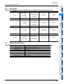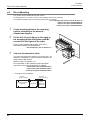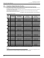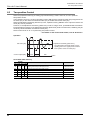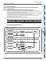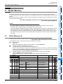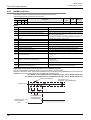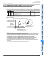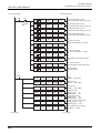
1
FX3U-4LC
USER'S MANUAL
Safety Precautions
(Read these precautions before using.)
Before installation, operation, maintenance or inspection of this product, thoroughly read through and
understand this manual and the associated manuals. Also, take care to handle the module properly and
safely.
This manual classifies the safety precautions into two categories:
and
.
Indicates that incorrect handling may cause hazardous conditions, resulting in death or severe
injury.
Indicates that incorrect handling may cause hazardous conditions, resulting in medium or slight
personal injury or physical damage.
Depending on the circumstances, procedures indicated by
may also cause severe injury.
It is important to follow all precautions for personal safety.
Store this manual in a safe place so that it can be taken out and read whenever necessary. Always forward it
to the end user.
1. DESIGN PRECAUTIONS
Reference
•
Make sure to include the following safety circuits outside the PLC to ensure safe system operation even during
external power supply problems or PLC failure.
Otherwise, malfunctions may cause serious accidents.
1) Above all, the following components should be included: an emergency stop circuit, a protection circuit, an
interlock circuit for opposite movements (such as normal vs. reverse rotation), and an interlock circuit (to prevent
damage to the equipment at the upper and lower positioning limits).
2) Note that when the PLC CPU detects an error, such as a watchdog timer error, during self-diagnosis, all outputs
are turned off. Also, when an error that cannot be detected by the PLC CPU occurs in an input/output control
block, output control may be disabled.
External circuits and mechanisms should be designed to ensure safe machinery operation in such a case.
3) Note that when an error occurs in a relay, triac or transistor output device, the output could be held either on or
off.
For output signals that may lead to serious accidents, external circuits and mechanisms should be designed to
ensure safe machinery operation in such a case.
17
Reference
•
•
•
Do not bundle the control line together with or lay it close to the main circuit or power line. As a guideline, lay the
control line at least 100mm (3.94") or more away from the main circuit or power line.
Noise may cause malfunctions.
Ground the shield wire or shield of the shielded cable at one point on the PLC. However, do not ground them at the
same point as the high-voltage lines.
Noise may cause malfunctions.
Install module so that excessive force will not be applied to the terminal blocks.
Failure to do so may result in wire damage/breakage or PLC failure.
(1)
17
Safety Precautions
(Read these precautions before using.)
2. INSTALLATION PRECAUTIONS
Reference
•
Make sure to shut down all phases of the power supply externally before installing.
Failure to do so may cause electric shock or damage to the product.
24
Reference
•
•
•
•
•
•
•
•
Use the product within the generic environment specifications described in PLC main unit manual (Hardware
Edition).
Never use the product in areas with excessive dust, oily smoke, conductive dusts, corrosive gas (salt air, Cl2, H2S,
SO2, or NO2), flammable gas, vibration or impacts, or expose it to high temperature, condensation, or rain and
wind.
If the product is used in such conditions, electric shock, fire, malfunctions, deterioration or damage may occur.
Do not touch the conductive parts of the product directly.
Doing so may cause device failures or malfunctions.
Install the product securely using a DIN rail or mounting screws.
Install the product on a flat surface.
If the mounting surface is rough, undue force will be applied to the PC board, thereby causing nonconformities.
When drilling screw holes or wiring, make sure that cutting and wiring debris do not enter the ventilation slits.
Failure to do so may cause fire, equipment failures or malfunctions.
Be sure to remove the dust proof sheet from the PLC's ventilation port when installation work is completed.
Failure to do so may cause fire, equipment failures or malfunctions.
Connect extension cables securely to their designated connectors.
Loose connections may cause malfunctions.
Turn off the power to the PLC before attaching or detaching the following devices.
Failure to do so may cause device failures or malfunctions.
- Peripheral devices, display modules, expansion boards and special adapters
- I/O extension units/blocks, FX Series terminal block and the special function units/blocks
- Battery and memory cassette
24
3. WIRING PRECAUTIONS
Reference
•
Make sure to cut off all phases of the power supply externally before attempting wiring work.
Failure to do so may cause electric shock.
27
Reference
•
•
•
•
•
•
Connect the AC power supply to the dedicated terminals specified in this manual.
If an AC power supply is connected to a DC input/output terminal or DC power supply terminal, the PLC will burn
out.
Do not wire vacant terminals externally.
Doing so may damage the product.
Use class D grounding (grounding resistance of 100 or less) with a wire of 2mm2 or thicker on the grounding
terminal of the PLC.
However, do not connect the ground terminal at the same point as a heavy electrical system.
When drilling screw holes or wiring, make sure cutting or wire debris does not enter the ventilation slits.
Failure to do so may cause fire, equipment failures or malfunctions.
Make sure to observe the following precautions in order to prevent malfunctions under the influence of noise.
- Do not bundle the power line or twisted shielded cable together with or lay it close to the main circuit, highvoltage line, or load line.
Otherwise, noise disturbance and/or surge induction are likely to take place. As a guideline, lay the control line
at least 100mm (3.94") or more away from the main circuit, high-voltage line, or load line.
- Ground the shield wire or shield of the shielded cable at one point on the PLC. However, do not use common
grounding with heavy electrical systems.
Make sure to properly wire to the terminal blocks in accordance with the following precautions.
Failure to do so may cause electric shock, equipment failures, a short-circuit, wire breakage, malfunctions, or
damage to the product.
- The disposal size of the cable end should follow the dimensions described in the manual.
- Tightening torque should follow the specifications in the manual.
(2)
27
Safety Precautions
(Read these precautions before using.)
4. STARTUP AND MAINTENANCE PRECAUTIONS
Reference
•
•
•
Do not touch any terminal while the PLC's power is on.
Doing so may cause electric shock or malfunctions.
Before cleaning or retightening terminals, cut off all phases of the power supply externally.
Failure to do so may cause electric shock.
Before modifying or disrupting the program in operation or running the PLC, carefully read through this manual and
the associated manuals and ensure the safety of the operation.
An operation error may damage the machinery or cause accidents.
125
141
Reference
•
•
•
Do not disassemble or modify the PLC.
Doing so may cause fire, equipment failures, or malfunctions.
For repair, contact your local Mitsubishi Electric distributor.
Turn off the power to the PLC before connecting or disconnecting any extension cable.
Failure to do so may cause equipment failures or malfunctions.
Turn off the power to the PLC before attaching or detaching the following devices.
Failure to do so may cause equipment failures or malfunctions.
- Peripheral devices, display modules, expansion boards and special adapters
- I/O extension units/blocks, FX Series terminal block and the special function units/blocks
- Battery and memory cassette
125
141
5. DISPOSAL PRECAUTIONS
Reference
•
Please contact a certified electronic waste disposal company for the environmentally safe recycling and disposal of
your device.
17
6. TRANSPORTATION PRECAUTIONS
Reference
•
The PLC is a precision instrument. During transportation, avoid impacts larger than those specified in the general
specifications of the PLC main unit manual.
Failure to do so may cause failures in the PLC.
After transportation, verify the operations of the PLC.
(3)
17
MEMO
(4)
FX3U-4LC User's Manual
FX3U-4LC
User's Manual
Manual number
JY997D39101
Manual revision
B
Date
5/2010
Foreword
This manual describes the FX3U-4LC temperature control block and should be read and understood before
attempting to install the hardware.
Store this manual in a safe place so that you can take it out and read it whenever necessary. Always forward
it to the end user.
This manual confers no industrial property rights or any rights of any other kind, nor does it confer any patent licenses. Mitsubishi
Electric Corporation cannot be held responsible for any problems involving industrial property rights which may occur as a result of
using the contents noted in this manual.
© 2010 MITSUBISHI ELECTRIC CORPORATION
1
FX3U-4LC User's Manual
Outline Precautions
• This manual provides information for the use of the FX3U-4LC temperature control block.
The manual has been written to be used by trained and competent personnel. The definition of such a
person or persons is as follows;
1) Any engineer who is responsible for the planning, design and construction of automatic equipment using
the product associated with this manual should be of a competent nature, trained and qualified to the
local and national standards required to fulfill that role. These engineers should be fully aware of all
aspects of safety with aspects regarding to automated equipment.
2) Any commissioning or maintenance engineer must be of a competent nature, trained and qualified to the
local and national standards required to fulfill the job. These engineers should also be trained in the use
and maintenance of the completed product. This includes being familiar with all associated manuals and
documentation for the product. All maintenance should be carried out in accordance with established
safety practices.
3) All operators of the completed equipment should be trained to use that product in a safe and coordinated
manner in compliance with established safety practices. The operators should also be familiar with
documentation that is connected with the actual operation of the completed equipment.
Note: the term 'completed equipment' refers to a third party constructed device that contains or uses the
product associated with this manual.
• This product has been manufactured as a general-purpose part for general industries, and has not been
designed or manufactured to be incorporated in a device or system used in purposes related to human life.
• Before using the product for special purposes such as nuclear power, electric power, aerospace, medicine
or passenger movement vehicles, consult with Mitsubishi Electric.
• This product has been manufactured under strict quality control. However when installing the product
where major accidents or losses could occur if the product fails, install appropriate backup or failsafe
functions into the system.
• When combining this product with other products, please confirm the standards and codes of regulation to
which the user should follow. Moreover, please confirm the compatibility of this product with the system,
machines, and apparatuses to be used.
• If there is doubt at any stage during installation of the product, always consult a professional electrical
engineer who is qualified and trained in the local and national standards. If there is doubt about the
operation or use, please consult the nearest Mitsubishi Electric distributor.
• Since the examples within this manual, technical bulletin, catalog, etc. are used as reference; please use it
after confirming the function and safety of the equipment and system. Mitsubishi Electric will not accept
responsibility for actual use of the product based on these illustrative examples.
• The content, specification etc. of this manual may be changed for improvement without notice.
• The information in this manual has been carefully checked and is believed to be accurate; however, if you
notice any doubtful point, error, etc., please contact the nearest Mitsubishi Electric distributor.
Registration
• The company name and the product name to be described in this manual are the registered trademarks or
trademarks of each company.
2
FX3U-4LC User's Manual
Table of Contents
SAFETY PRECAUTIONS .................................................................................................. (1)
Standards................................................................................................................................... 7
Certification of UL, cUL standards ....................................................................................................... 7
Compliance with EC directive (CE Marking) ........................................................................................ 7
Associated Manuals.................................................................................................................. 9
Generic Names and Abbreviations Used in the Manual ...................................................... 11
Reading the Manual ................................................................................................................ 13
1. Introduction
14
1.1 Outline........................................................................................................................................... 14
1.1.1 Major features of the FX3U-4LC .................................................................................................... 14
1.2 External Dimensions and Part Names .......................................................................................... 15
1.3 Terminal Layout ............................................................................................................................ 16
1.4 Power and Status LEDs ................................................................................................................ 16
2. Specification
2.1
2.2
2.3
2.4
17
General Specifications .................................................................................................................. 18
Power Supply Specifications......................................................................................................... 18
Performance Specifications .......................................................................................................... 18
Input Specifications ....................................................................................................................... 19
2.4.1 Temperature input specifications................................................................................................... 19
2.4.2 Measurement precision ................................................................................................................. 20
2.4.3 Current detector (CT) input specifications ..................................................................................... 20
2.5 Input Type ..................................................................................................................................... 21
2.6 Output Specifications .................................................................................................................... 21
3. System Configuration
22
3.1 General Configuration ................................................................................................................... 22
3.2 Applicable PLC.............................................................................................................................. 23
3.3 Connection with PLC..................................................................................................................... 23
4. Installation
24
4.1 DIN rail Mounting .......................................................................................................................... 25
4.2 Direct Mounting ............................................................................................................................. 26
5. Wiring
27
5.1 Power Supply Wiring..................................................................................................................... 28
5.1.1 Power supply wiring....................................................................................................................... 28
5.1.2 Grounding...................................................................................................................................... 28
5.2 Input Wiring ................................................................................................................................... 29
5.2.1 Wiring example of thermocouple ................................................................................................... 29
5.2.2 Wiring example of resistance thermometer ................................................................................... 29
5.2.3 Wiring example of micro voltage input........................................................................................... 30
5.3 Output Wiring ................................................................................................................................ 31
5.4 Terminal Screw and Tightening Torque ........................................................................................ 32
3
FX3U-4LC User's Manual
6. Introduction of Functions
6.1
6.2
6.3
6.4
33
Functions List ................................................................................................................................ 33
Control Mode Switch Function ...................................................................................................... 34
Transistor Output Selection Function............................................................................................ 36
PID control .................................................................................................................................... 38
6.4.1 Easy PID control with two degrees of freedom.............................................................................. 38
6.4.2 Overshoot prevention function....................................................................................................... 39
6.5 Two-position Control ..................................................................................................................... 40
6.6 Heating/cooling PID control........................................................................................................... 41
6.6.1
6.6.2
6.6.3
6.6.4
Heating/cooling PID control ........................................................................................................... 41
Overshoot prevention function....................................................................................................... 42
Overlap/dead band function .......................................................................................................... 43
Cooling method ............................................................................................................................. 44
6.7 Cascade control ............................................................................................................................ 45
6.7.1 Cascade control............................................................................................................................. 45
6.7.2 Tuning during cascade control ...................................................................................................... 47
6.7.3 SV tracking selection function ....................................................................................................... 48
6.8 Auto Tuning Function .................................................................................................................... 49
6.8.1 AT (Auto tuning) ............................................................................................................................ 49
6.8.2 Conditions for performing and aborting AT (auto tuning) .............................................................. 51
6.8.3 AT (auto tuning) bias ..................................................................................................................... 53
6.9 Startup Tuning Function................................................................................................................ 54
6.9.1 ST (startup tuning)......................................................................................................................... 54
6.9.2 Conditions for performing and aborting ST (startup tuning) .......................................................... 56
6.10 AUTO/MANUAL mode changeover ............................................................................................ 58
6.10.1 AUTO mode and MANUAL mode................................................................................................ 58
6.10.2 Balance-less, bump-less function................................................................................................ 59
6.11 Heater Disconnection Alarm Function (HBA).............................................................................. 60
6.11.1 Heater disconnection alarm function ........................................................................................... 60
6.11.2 Number of times of heater disconnection alarm delay ................................................................ 61
6.12 Loop Breaking Alarm Function (LBA).......................................................................................... 62
6.12.1 Loop breaking alarm function ...................................................................................................... 62
6.12.2 Loop breaking alarm dead zone (LBD)........................................................................................ 64
7. Alarm
65
7.1 Alarm List ...................................................................................................................................... 65
7.2 Alarm Functions ............................................................................................................................ 67
7.2.1
7.2.2
7.2.3
7.2.4
7.2.5
7.2.6
7.2.7
7.2.8
Upper limit input value alarm ......................................................................................................... 67
Lower limit input value alarm ......................................................................................................... 67
Upper limit deviation alarm ............................................................................................................ 68
Lower limit deviation alarm ............................................................................................................ 68
Upper/lower limit deviation ............................................................................................................ 68
Range alarm .................................................................................................................................. 69
Alarm wait operation...................................................................................................................... 69
Alarm re-wait operation ................................................................................................................. 70
7.3 Alarm Dead Zone Setting.............................................................................................................. 71
7.4 Number of Times of Alarm Delay .................................................................................................. 72
4
FX3U-4LC User's Manual
8. Buffer Memory
73
8.1 Buffer Memory List ........................................................................................................................ 73
8.2 Buffer Memory Details................................................................................................................... 77
8.2.1
8.2.2
8.2.3
8.2.4
[BFM#0] Flag ................................................................................................................................. 77
[BFM#1 to 4] Event........................................................................................................................ 78
[BFM#5 to 8] Measured value (PV) ............................................................................................... 79
[BFM#9 to 12] Control output value (MV) monitor/
Heating control output value (MV) monitor ............................................................................... 80
8.2.5 [BFM#13 to 16] Cooling control output value (MV) monitor........................................................... 80
8.2.6 [BFM#17 to 20] Control output flag................................................................................................ 81
8.2.7 [BFM#21 to 24] Heater current measured value ........................................................................... 82
8.2.8 [BFM#25 to 28] External input value ............................................................................................. 82
8.2.9 [BFM#29] Control start/stop changeover....................................................................................... 82
8.2.10 [BFM#30] FX Series model code................................................................................................. 82
8.2.11 [BFM#32 to 35] External output value/Heating external output value monitor ............................ 83
8.2.12 [BFM#36 to 39] Cooling external output value monitor ............................................................... 83
8.2.13 [BFM#40 to 43] Set value monitor ............................................................................................... 83
8.2.14 [BFM#44 to 47] Control mode monitor ........................................................................................ 84
8.2.15 [BFM#48][BFM#88][BFM#128][BFM#168] Set value (SV) .......................................................... 85
8.2.16 [BFM#49 to 52][BFM#89 to 92][BFM#129 to 132][BFM#169 to 172]
Alarm setting value 1 to 4 ......................................................................................................... 85
8.2.17 [BFM#53][BFM#93][BFM#133][BFM#173] Heater disconnection alarm set value ...................... 86
8.2.18 [BFM#54][BFM#94][BFM#134][BFM#174] AUTO/MANUAL mode changeover ......................... 86
8.2.19 [BFM#55][BFM#95][BFM#135][BFM#175] MANUAL output set value........................................ 87
8.2.20 [BFM#56][BFM#96][BFM#136][BFM#176] AT (auto tuning) execution command ...................... 87
8.2.21 [BFM#57][BFM#97][BFM#137][BFM#177] Operation mode ....................................................... 88
8.2.22 [BFM#58][BFM#98][BFM#138][BFM#178] Proportional band (P)/
Heating proportional band (P)................................................................................................... 89
8.2.23 [BFM#59][BFM#99][BFM#139][BFM#179] Cooling proportional band (P) .................................. 89
8.2.24 [BFM#60][BFM#100][BFM#140][BFM#180] Integral time (I) ....................................................... 90
8.2.25 [BFM#61][BFM#101][BFM#141][BFM#181] Derivative time (D) ................................................. 90
8.2.26 [BFM#62][BFM#102][BFM#142][BFM#182] Control response parameter .................................. 91
8.2.27 [BFM#63][BFM#103][BFM#143][BFM#183] Overlap/Dead band ................................................ 92
8.2.28 [BFM#64][BFM#104][BFM#144][BFM#184] Output limiter upper limit/
Heating upper output limiter...................................................................................................... 93
8.2.29 [BFM#65][BFM#105][BFM#145][BFM#185] Output limiter lower limit......................................... 94
8.2.30 [BFM#66][BFM#106][BFM#146][BFM#186] Cooling upper output limiter setting........................ 94
8.2.31 [BFM#67][BFM#107][BFM#147][BFM#187] Output change ratio limiter ..................................... 95
8.2.32 [BFM#68][BFM#108][BFM#148][BFM#188] Sensor correction value setting.............................. 96
8.2.33 [BFM#69][BFM#109][BFM#149][BFM#189] Adjustment sensitivity (dead zone) setting............. 97
8.2.34 [BFM#70][BFM#110][BFM#150][BFM#190] Control output cycle setting/
Heating control output period setting ........................................................................................ 98
8.2.35 [BFM#71][BFM#111][BFM#151][BFM#191] Cooling control output period setting...................... 98
8.2.36 [BFM#72][BFM#112][BFM#152][BFM#192] Primary delay digital filter setting ........................... 99
8.2.37 [BFM#73][BFM#113][BFM#153][BFM#193] Setting change ratio limiter................................... 100
8.2.38 [BFM#74][BFM#114][BFM#154][BFM#194] AT (auto tuning) bias............................................ 101
8.2.39 [BFM#75][BFM#115][BFM#155][BFM#195] Normal/reverse operation selection ..................... 102
8.2.40 [BFM#76][BFM#116][BFM#156][BFM#196] Setting limiter upper limit...................................... 103
8.2.41 [BFM#77][BFM#117][BFM#157][BFM#197] Setting limiter lower limit ...................................... 103
8.2.42 [BFM#78][BFM#118][BFM#158][BFM#198] Loop breaking alarm judgement time................... 104
8.2.43 [BFM#79][BFM#119][BFM#159][BFM#199] Loop breaking alarm dead zone........................... 105
8.2.44 [BFM#80][BFM#120][BFM#160][BFM#200] Micro voltage input scaling upper limit ................. 106
8.2.45 [BFM#81][BFM#121][BFM#161][BFM#201] Micro voltage input scaling lower limit.................. 106
8.2.46 [BFM#82][BFM#122][BFM#162][BFM#202] External input range upper limit ........................... 106
8.2.47 [BFM#83][BFM#123][BFM#163][BFM#203] External input range lower limit ............................ 106
8.2.48 [BFM#84][BFM#124][BFM#164][BFM#204] External output range upper limit ......................... 107
8.2.49 [BFM#85][BFM#125][BFM#165][BFM#205] External output range lower limit.......................... 107
8.2.50 [BFM#86][BFM#126][BFM#166][BFM#206] Transistor output selection ................................... 108
8.2.51 [BFM#87][BFM#127][BFM#167][BFM#207] ST (startup tuning) execution command .............. 109
8.2.52 [BFM#208][BFM#214][BFM#220][BFM#226] Input type ........................................................... 110
8.2.53 [BFM#209 to #212][BFM#215 to #218][BFM#221 to #224][BFM#227 to #230]
Alarm mode setting 1 to 4....................................................................................................... 111
5
FX3U-4LC User's Manual
8.2.54
8.2.55
8.2.56
8.2.57
8.2.58
8.2.59
8.2.60
8.2.61
8.2.62
8.2.63
8.2.64
8.2.65
8.2.66
8.2.67
8.2.68
8.2.69
8.2.70
8.2.71
[BFM#232] Cooling method setting ........................................................................................... 112
[BFM#233] Alarm dead band setting ......................................................................................... 113
[BFM#234] Alarm delay count ................................................................................................... 114
[BFM#235] Number of times of heater disconnection alarm delay/
Number of times of current error detection when output is OFF delay ................................... 115
[BFM#236] Temperature rise completion range setting ............................................................ 115
[BFM#237] Temperature rise completion soak time.................................................................. 116
[BFM#238] CT monitor method switch ...................................................................................... 117
[BFM#239] CT ratio setting........................................................................................................ 117
[BFM#240, #241] Control mode switch ..................................................................................... 118
[BFM#242, #243] SV tracking selection .................................................................................... 119
[BFM#244, #245] Cascade ON/OFF ......................................................................................... 120
[BFM#246, #247] Cascade gain ................................................................................................ 120
[BFM#248, #249] Cascade bias ................................................................................................ 121
[BFM#250, #251] Cascade monitor........................................................................................... 121
[BFM#252] Set value range error address ................................................................................ 122
[BFM#253] Error reset command .............................................................................................. 122
[BFM#254] Set value backup command.................................................................................... 123
[BFM#255] Initialization command ............................................................................................ 124
9. Program Examples
125
9.1 Reading/Writing Buffer Memory .................................................................................................. 126
9.1.1 Assigned unit number.................................................................................................................. 126
9.1.2 How to read/write from/to buffer memory .................................................................................... 126
9.2 Example of a Program for PID Control........................................................................................ 131
9.2.1
9.2.2
9.2.3
9.2.4
System configuration ................................................................................................................... 131
Conditions of operation................................................................................................................ 131
Device assignments .................................................................................................................... 132
Sequence program ...................................................................................................................... 133
9.3 Example of a Program for Heating/Cooling PID Control ............................................................. 136
9.3.1
9.3.2
9.3.3
9.3.4
System configuration ................................................................................................................... 136
Conditions of operation................................................................................................................ 136
Device assignments .................................................................................................................... 137
Sequence program ...................................................................................................................... 138
10. Troubleshooting
141
10.1 Troubleshooting Procedure....................................................................................................... 142
10.1.1 How to reset an error................................................................................................................. 142
10.2 Diagnostics on the PLC Main Unit ............................................................................................ 143
10.2.1 POWER (POW) LED [on/flashing/off]........................................................................................ 143
10.2.2 BATT (BAT) LED [on/off] ........................................................................................................... 143
10.2.3 ERROR (ERR) LED [on/flashing/off] ......................................................................................... 144
Appendix A: Version Information
145
Appendix A-1 Version Information ............................................................................................ 145
Appendix A-1-1 Version check method ................................................................................................ 145
Appendix A-1-2 Version upgrade history.............................................................................................. 145
Warranty................................................................................................................................. 147
Revised History ..................................................................................................................... 148
6
FX3U-4LC User's Manual
Standards
Standards
Certification of UL, cUL standards
FX3U-4LC units comply with the UL standards (UL, cUL).
UL, cUL File number :E95239
Regarding the standards that comply with the main unit, please refer to either the FX series product catalog or
consult with your nearest Mitsubishi product provider.
Compliance with EC directive (CE Marking)
This document does not guarantee that a mechanical system including this product will comply with the
following standards.
Compliance to EMC directive and LVD directive for the entire mechanical module should be checked by the
user / manufacturer. For more information please consult with your nearest Mitsubishi product provider.
Regarding the standards that comply with the main unit, please refer to either the FX series product catalog or
consult with your nearest Mitsubishi product provider.
Requirement for Compliance with EMC directive
The following products have shown compliance through direct testing (of the identified standards below) and
design analysis (through the creation of a technical construction file) to the European Directive for
Electromagnetic Compatibility (2004/108/EC) when used as directed by the appropriate documentation.
Attention
• This product is designed for use in industrial applications.
Note
• Manufactured by:
Mitsubishi Electric Corporation
2-7-3 Marunouchi, Chiyoda-ku, Tokyo, 100-8310 Japan
• Manufactured at:
Mitsubishi Electric Corporation Himeji Works
840 Chiyoda-machi, Himeji, Hyogo, 670-8677 Japan
• Authorized Representative in the European Community:
Mitsubishi Electric Europe B.V.
Gothaer Str. 8, 40880 Ratingen, Germany
Type: Programmable Controller (Open Type Equipment)
Models: MELSEC FX3U series manufactured
from December 1st, 2009
FX3U-4LC
Standard
EN61131-2:2007
Programmable controllers
- Equipment requirements and tests
Remark
Compliance with all relevant aspects of the standard.
EMI
• Radiated Emissions
• Conducted Emissions
EMS
• Radiated electromagnetic field
• Fast Transient burst
• Electrostatic discharge
• High-energy surge
• Voltage drops and interruptions
• Conducted RF
• Power frequency magnetic field
7
FX3U-4LC User's Manual
Standards
Caution to conform with EC Directives
The FX3U-4LC have been found to be compliant to the European standards in the aforesaid manual and
directive. However, for the very best performance from what are in fact delicate measuring and controlled
output device Mitsubishi Electric would like to make the following points;
As analog devices are sensitive by nature, their use should be considered carefully. For users of proprietary
cables (integral with sensors or actuators), these users should follow those manufacturers installation
requirements.
Mitsubishi Electric recommend that shielded cables should be used. If NO other EMC protection is provided,
then users may experience temporary loss or accuracy between ±10% in very heavy industrial areas.
However, Mitsubishi Electric suggest that if adequate EMC precautions are followed for the users complete
control system, users should expect accuracy as specified in this manual.
• Sensitive analog cable should not be laid in the same trunking or cable conduit as high voltage cabling.
Where possible users should run analog cables separately.
• Good cable shielding should be used. When terminating the shield at Earth - ensure that no earth loops are
accidentally created.
• When reading analog values, EMC accuracy can be improved out by averaging the readings. This can be
achieved either through functions on the analog special function blocks for or through a users program in
the FX3G/FX3U/FX3UC Series PLC main unit.
• Installation in Enclosure
Programmable logic controllers are open-type devices that must be installed and used within conductive
control cabinets. Please use the programmable logic controller while installed within a conductive shielded
control cabinet. Please secure the cabinet door to the control cabinet (for conduction).
Installation within a control cabinet greatly affects the safety of the system and aids in shielding noise from
the programmable logic controller.
8
FX3U-4LC User's Manual
Associated Manuals
Associated Manuals
Only the installation manual is packed together with the FX3U-4LC temperature control block.
For a detailed explanation of the FX3U-4LC temperature control block, refer to this manual.
For the hardware information and instructions on the PLC main unit, refer to the respective manuals.
Refer to these manuals
Refer to the appropriate equipment manual
For a detailed explanation, refer to an additional manual
Title of manual
Document
number
Description
Model code
Manual for the Main Unit
FX3G Series PLCs Main Unit
Supplied
Manual
FX3G Series
Hardware Manual
Describes FX3G Series PLC specification for I/O, wiring
and installation extracted from the FX3G User's Manual
JY997D33401 - Hardware Edition.
For details, refer to FX3G Series User's Manual Hardware Edition.
Additional
Manual
FX3G Series
User's Manual
- Hardware Edition
JY997D31301
Describes FX3G Series PLC specification details for I/O,
wiring, installation and maintenance.
-
09R521
FX3U Series PLCs Main Unit
Supplied
Manual
FX3U Series
Hardware Manual
Describes FX3U Series PLC specification for I/O, wiring
and installation extracted from the FX3U User's Manual JY997D18801 Hardware Edition.
For details, refer to FX3U Series User's Manual Hardware Edition.
Additional
Manual
FX3U Series
User's Manual
- Hardware Edition
JY997D16501
Describes FX3U Series PLC specification details for I/O,
wiring, installation and maintenance.
-
09R516
FX3UC Series PLCs Main Unit
Supplied
Manual
FX3UC(D,DSS) Series
Hardware Manual
Describes FX3UC(D,DSS) Series PLC specification for I/
O, wiring and installation extracted from the FX3UC
JY997D28601 Series User's Manual - Hardware Edition.
For details, refer to FX3UC Series User's Manual Hardware Edition.
Supplied
Manual
FX3UC-32MT-LT-2
Hardware Manual
Describes FX3UC-32MT-LT-2 specification for I/O,
wiring and installation extracted from the FX3UC User's
JY997D31601 Manual - Hardware Edition.
For details, refer to FX3UC Series User's Manual Hardware Edition.
-
Supplied
Manual
Describes FX3UC-32MT-LT specification for I/O, wiring
FX3UC-32MT-LT
and installation extracted from the FX3UC User's Manual
Hardware Manual
JY997D12701 - Hardware Edition.
(Only Japanese document)
For details, refer to FX3UC Series User's Manual Hardware Edition.
-
Additional
Manual
FX3UC Series
User's Manual
- Hardware Edition
-
JY997D28701
Describes FX3UC Series PLC specification details
for I/O, wiring, installation and maintenance.
09R519
JY997D16601
Describes FX3G/FX3U/FX3UC Series PLC
programming for basic/applied instructions and devices.
09R517
Programming for FX3G/FX3U/FX3UC Series
Additional
Manual
FX3G/FX3U/FX3UC Series
Programming Manual
- Basic & Applied
Instruction Edition
Manuals for analog control
Additional
Manual
FX3G/FX3U/FX3UC Series
User's Manual
- Analog Control Edition
Details of analog special function block
JY997D16701 (FX3U-4AD, FX3U-4DA, FX3UC-4AD) and
analog special adapter (FX3U-***-**-ADP)
09R619
9
FX3U-4LC User's Manual
Associated Manuals
Title of manual
Document
number
Description
Model code
Manuals for FX3U-4LC temperature control block
10
Supplied
Manual
FX3U-4LC
Installation Manual
JY997D38901
Describes installation specifications for the FX3U-4LC
temperature control block extracted from the FX3U-4LC
User's Manual.
For details, refer to FX3U-4LC User's Manual.
-
Additional
Manual
FX3U-4LC
User's Manual
(This Manual)
JY997D39101
Describes details of the FX3U-4LC temperature control
block.
09R625
FX3U-4LC User's Manual
Generic Names and Abbreviations Used in the Manual
Generic Names and Abbreviations Used in the Manual
Generic name or abbreviation
Description
PLC
FX3G series
FX3G PLC or main unit
FX3U series
FX3U PLC or main unit
FX3UC series
FX3UC PLC or main unit
Generic name for FX3G Series PLC
Generic name for FX3G Series PLC main unit
Generic name for FX3U Series PLC
Generic name for FX3U Series PLC main unit
Generic name for FX3UC Series PLC
Generic name for FX3UC Series PLC main unit
Expansion board
Expansion board
Generic name for expansion board
The number of connectable units, however, depends on the type of main unit.
To check the number of connectable units, refer to the User's Manual - Hardware Edition of the main
unit to be used for your system.
Special adapter
Special adapter
Generic name for high-speed input/output special adapter, communication special adapter, analog
special adapter, and CF card special adapter.
The number of connectable units, however, depends on the type of main unit.
To check the number of connectable units, refer to the User's Manual - Hardware Edition of the main
unit to be used for your system.
Extension equipment
I/O extension unit/block
Generic name for input/output powered extension unit and input/output extension block
The number of connectable units, however, depends on the type of main unit.
To check the number of connectable units, refer to the User's Manual - Hardware Edition of the main
unit to be used for your system.
Special function unit/block or
Special extension unit
Generic name for special function unit and special function block
The number of connectable units, however, depends on the type of main unit.
To check the number of connectable units, refer to the User's Manual - Hardware Edition of the main
unit to be used for your system.
Special function unit
Generic name for special function unit
Special function block
Generic name for special function block
The number of connectable units, however, depends on the type of main unit.
To check the number of connectable units, refer to the User's Manual - Hardware Edition of the main
unit to be used for your system.
4LC
Abbreviated name for FX3U-4LC
Optional unit
Memory cassette
Generic name for FX3U-FLROM-16, FX3U-FLROM-64, FX3U-FLROM-64L
Battery
Abbreviated name for FX3U-32BL
FX Series terminal block
FX-16E-TB, FX-32E-TB, FX-16EX-A1-TB, FX-16EYR-TB, FX-16EYT-TB, FX-16EYT-H-TB,
FX-16EYS-TB, FX-16E-TB/UL, FX-32E-TB/UL, FX-16EYR-ES-TB/UL, FX-16EYT-ES-TB/UL,
FX-16EYT-ESS-TB/UL, FX-16EYS-ES-TB/UL
Peripheral unit
Peripheral unit
Generic name for programming software, handy programming panel, and indicator
Programming tool
Programming tool
Generic name for programming software and handy programming panel
Programming software
Generic name for programming software
GX Developer
Generic name for SW
FX-PCS/WIN(-E)
Generic name for FX-PCS/WIN or FX-PCS/WIN-E programming software package
Handy programming panel (HPP)
D5C-GPPW-J/SW
D5C-GPPW-E programming software package
Generic name for FX-30P, FX-20P-SET0, FX-20P, FX-20P-E-SET0 and FX-20P-E
Indicator
GOT1000 series
Generic name for GT15, GT11 and GT10
GOT-900 series
Generic name for GOT-A900 series and GOT-F900 series
GOT-A900 series
Generic name for GOT-A900 series
GOT-F900 series
Generic name for GOT-F900 series
ET-940 series
Generic name for ET-940 series
Only manuals in Japanese are available for these products
11
FX3U-4LC User's Manual
Generic name or abbreviation
Generic Names and Abbreviations Used in the Manual
Description
Manual
12
FX3G Hardware Edition
FX3G Series User's Manual - Hardware Edition
FX3U Hardware Edition
FX3U Series User's Manual - Hardware Edition
FX3UC Hardware Edition
FX3UC Series User's Manual - Hardware Edition
Programming manual
FX3G/FX3U/FX3UC Series Programming Manual - Basic and Applied Instructions Edition
Communication control Edition
FX Series User's Manual - Data Communication Edition
Analog control Edition
FX3G/FX3U/FX3UC Series User's Manual - Analog Control Edition
Positioning control Edition
FX3G/FX3U/FX3UC Series User's Manual - Positioning Control Edition
FX3U-4LC User's Manual
Reading the Manual
Reading the Manual
In this manual, the following formats are used for describing the common items.
Shows the manual title.
Shows the title of the chapter and the title
Indexes the chapter number.
This area shows the
manual title for the current
page.
of the section.
This area shows the title of the chapter and the
title of the section for the current page.
The right side of each page
indexes the chapter number
for the page currently opened.
Shows the reference.
The " " mark indicates
a reference destination
and reference manual.
The above is different from the actual page, as it is provided for explanation only.
13
1 Introduction
FX3U-4LC User's Manual
1.
1.1
1.1 Outline
Introduction
Outline
The temperature control block FX 3U -4LC (hereinafter called 4LC) equipped with 4 channel input
(thermocouples, resistance thermometer and micro voltage input), 4 points output (open collector transistor)
and 4 points CT input is a special function block for thermometer control.
1.1.1
Major features of the FX3U-4LC
The 4LC has the following features.
1) Allows inputs from 4 channels.
The 4LC supports temperature sensor inputs from thermocouples and resistance thermometers as well
as micro voltage inputs.
2) Incorporates outputs from 4 channels.
The 4LC incorporates NPN open collector transistor outputs.
3) Performs heating/cooling PID control.
The 4LC handles two systems of outputs, heating output and cooling output, and performs heating/
cooling control.
4) Performs cascade control.
The 4LC performs cascade control through combination of two control loops, the master loop and slave
loop.
5) Performs control using external analog inputs/outputs.
The 4LC performs PID control using voltage/current inputs and voltage/current outputs when combined
with a special function block for analog input/output.
6) Performs auto tuning.
The 4LC can automatically measure, calculate and set optimal PID constants for the preset temperature.
7) Performs startup tuning.
The 4LC can automatically calculate and set PID constants based on the response characteristics of the
control target when control is started or when the set value (SV) is changed.
8) Detects heater disconnection.
The 4LC can detect heater disconnection using the current detector (CT).
9) Backs up set values using the EEPROM.
The 4LC can back up set values stored in buffer memories using the built-in EEPROM.
10) Connectable PLC
Connect the 4LC to the FX3G/FX3U/FX3UC Series PLC.
An FX2NC-CNV-IF or FX3UC-1PS-5V is necessary to connect the 4LC with the FX3UC PLC.
14
1 Introduction
FX3U-4LC User's Manual
1
External Dimensions and Part Names
2-Ø4.5mounting holes
[6]
[3] [4] [5]
[7]
2
[8]
Specification
82(3.23")
(mounting hole pitch)
90(3.55")
[1] [2]
Introduction
1.2
1.2 External Dimensions and Part Names
[9]
3
[4]
82(3.23")
(mounting hole pitch)
90(3.55")
System
Configuration
[3]
9(0.36")
86(3.39")
[Without cover]
[10]
[11]
4
[12]
Installation
[13]
[12]
Extension cable
[8]
DIN rail mounting groove
(DIN rail: DIN46277, 35mm (1.38") width)
[2]
Direct mounting hole
2 holes of 4.5 (0.18") (mounting screw: M4 screw)
[9]
DIN rail mounting hook
[3]
Terminal block covers
[10]
Power supply terminal block (M3 screw)
[4]
Terminal cover
[11]
Input terminal block (M3 screw)
[5]
Power LED (green)
[12]
Output terminal block (M3 screw)
[6]
Status LEDs (red)
[13]
Extension connector
[7]
Nameplate
→ Refer to Section 1.3.
7
→ Refer to Section 1.3.
Alarm
→ Refer to Section 1.4.
6
Introduction of
Functions
[1]
Wiring
[11]
5
Unit: mm(inches)
MASS(Weight): 0.4kg(0.88lbs)
Accessaries: Label for indication of special unit/block number,
Dust proof sheet,
Manual supplied with product
→ Refer to Section 1.3.
8
Buffer Memory
9
Program
Examples
10
Troubleshooting
15
1 Introduction
FX3U-4LC User's Manual
1.3
1.3 Terminal Layout
Terminal Layout
CT
FG
PTB/TC-/COM
24+
24-
PTA/ /
FG
PTB/TC+/VL+
PTB/TC-/COM
CT
OUT1
PTA/ /
FG
PTB/TC+/VL+
POWER
Color
Green
24V
Red
OUT1
Red
OUT2
Red
OUT3
Red
OUT4
Red
OUT2
PTB/TC-/COM
OUT3
COM1
OUT4
CH4
PTA/ /
PTB/TC+/VL+
CT
PTA/ /
PTB/TC+/VL+
Power and Status LEDs
LED display
16
CT
CT
CH3
1.4
PTB/TC-/COM
CH2
CT
CT
FG
CT
CH1
Status
Description
OFF
Power is not being supplied from the internal power supply (5V DC).
ON
Power is being supplied from the internal power supply (5V DC).
OFF
Power is not being supplied from the external power supply (24V DC).
ON
Power is being supplied from the external power supply (24V DC).
OFF
OUT1 output OFF
ON
OUT1 output ON
OFF
OUT2 output OFF
ON
OUT2 output ON
OFF
OUT3 output OFF
ON
OUT3 output ON
OFF
OUT4 output OFF
ON
OUT4 output ON
COM2
2 Specification
FX3U-4LC User's Manual
1
Introduction
2.
Specification
2
•
•
Do not bundle the control line together with or lay it close to the main circuit or power line. As a guideline, lay the control line at least
100mm (3.94") or more away from the main circuit or power line.
Noise may cause malfunctions.
Ground the shield wire or shield of the shielded cable at one point on the PLC. However, do not ground them at the same point as the
high-voltage lines.
Noise may cause malfunctions.
Install module so that excessive force will not be applied to the terminal blocks.
Failure to do so may result in wire damage/breakage or PLC failure.
6
Introduction of
Functions
DISPOSAL PRECAUTIONS
•
Please contact a certified electronic waste disposal company for the environmentally safe recycling and disposal of your device.
7
TRANSPORTATION PRECAUTIONS
The PLC is a precision instrument. During transportation, avoid impacts larger than those specified in the general specifications of the
PLC main unit manual.
Failure to do so may cause failures in the PLC.
After transportation, verify the operations of the PLC.
Alarm
•
5
Wiring
•
4
Installation
DESIGN PRECAUTIONS
•
3
System
Configuration
Make sure to include the following safety circuits outside the PLC to ensure safe system operation even during external power supply
problems or PLC failure.
Otherwise, malfunctions may cause serious accidents.
1) Above all, the following components should be included: an emergency stop circuit, a protection circuit, an interlock circuit for
opposite movements (such as normal vs. reverse rotation), and an interlock circuit (to prevent damage to the equipment at the
upper and lower positioning limits).
2) Note that when the PLC CPU detects an error, such as a watchdog timer error, during self-diagnosis, all outputs are turned off.
Also, when an error that cannot be detected by the PLC CPU occurs in an input/output control block, output control may be
disabled.
External circuits and mechanisms should be designed to ensure safe machinery operation in such a case.
3) Note that when an error occurs in a relay, triac or transistor output device, the output could be held either on or off.
For output signals that may lead to serious accidents, external circuits and mechanisms should be designed to ensure safe
machinery operation in such a case.
Specification
DESIGN PRECAUTIONS
8
Buffer Memory
9
Program
Examples
10
Troubleshooting
17
2 Specification
FX3U-4LC User's Manual
2.1
2.1 General Specifications
General Specifications
For items not listed below, specifications are the same as the of the PLC main unit.
For general specifications, refer to the manual of the PLC main unit.
→ Refer to FX3G Hardware Edition.
→ Refer to FX3U Hardware Edition.
→ Refer to FX3UC Hardware Edition.
Item
Specification
Dielectric withstand voltage
Insulation resistance
2.2
500V AC for one minute
5M
or more by 500V DC Megger
Power Supply Specifications
Item
2.3
Specification
Interface driving power
24V DC +20% -15% 50mA
Connect a 24V DC power supply to the terminal block.
CPU driving power
5V DC 160mA
5V DC power is supplied internally from the main unit.
Performance Specifications
Item
Control method
Control operation period
Set temperature range
Heater disconnection detection
Operation mode
Self-diagnosis function
Memory
Insulation method
Specification
Two-position control
PID control
Heating/cooling PID control
Cascade control
250ms/4ch
Equivalent to input range (Refer to Subsection 8.2.52.)
Alarm is detected by buffer memory
(Variable within range from 0.0 to 100.0A.)
0 : Not used
1 : Monitor
2 : Monitor + Alarm
3 : Monitor + Alarm + Control
(Selected by buffer memory)
Adjustment data check, input value check, watch dog timer check.
When abnormality is detected, transistor output turns OFF.
Built-in EEPROM (Number of times of overwrite : 100,000 times)
•
•
•
Number of I/O occupied points
18
Between all terminals and ground terminal
The photocoupler is used to insulate the analog input area from the PLC.
The DC/DC converter is used to insulate the power supply from the analog
inputs.
Channels are insulated from each other.
8 points
(Taken from either the input or output points of the PLC.)
2 Specification
FX3U-4LC User's Manual
2.4 Input Specifications
1
Introduction
2.4
Input Specifications
2.4.1
Temperature input specifications
Number of input points
Input type*1
2
Specification
Thermocouple
K, J, R, S, E, T, B, N JIS C 1602-1995
PLII, W5Re/W26Re, U, L
Specification
Item
Resistance thermometer
3-wire Pt100 JIS C 1604-1997
3-wire JPt100 JIS C 1604-1981
2-wire or 3-wire Pt1000 JIS C 1604-1997
3
4 points
Measurement precision
Resolution
Sampling period
Effect of input lead wire resistance
(When resistance thermometer is used)
Input impedance
Within ±1.0 C (When ambient temperature is 0 to 55 C)
However, within ± 2.0 °C while input value is
-150 to -100 C / within ± 3.0 C while input value is -200 to -150 °C
0.1 C (0.1 F), 1 C (1 F), 0.5 V or 5.0 V
Varies depending on input range of used sensors.
5
250ms/4ch
Approx.0.125 V/
3-wire type
Approx. 0.03%/ of full scale.
10 or less per 1-wire
2-wire type
Approx. 0.04%/ of full scale.
7.5 or less per 1-wire
1M
Approx.0.25mA (When resistance thermometer is used)
Operation when input is disconnected
Upscale
Operation when input is short-circuited
Downscale (When resistance thermometer is used)
*1.
6
or more
Introduction of
Functions
Sensor current
4
Wiring
Effect of external resistance
(When thermocouple is used)
Measurement accuracy differs depending on the type of
When ambient temperature
input, and the input range.
is 0 to 55 C
For specification details, refer to Subsection 2.4.2.
Installation
Cold contact temperature compensation error
Measurement accuracy differs depending on the type of
When ambient temperature
input, and the input range.
is 25 C±5 C
For specification details, refer to Subsection 2.4.2.
System
Configuration
Micro voltage input
A different input can be selected for each channel.
7
Alarm
8
Buffer Memory
9
Program
Examples
10
Troubleshooting
19
2 Specification
FX3U-4LC User's Manual
2.4.2
2.4 Input Specifications
Measurement precision
The measurement precision is as shown below. The measurement precision of the thermocouple does not
include the cold contact temperature compensation error. For the cold contact temperature compensation
error, refer to Subsection 2.4.1.
Digits below the minimum resolution (shown in the measurement precision below) of the input value are
rounded up.
1. When ambient temperature is 25 C±5 C
Input type
K, J, E, T, PLII, U, L
R, S, N, W5Re/W26Re
B
Pt100, JPt100, Pt1000
Input range
Measurement precision
Less than -100 C
±3.0 C±1digit
-100 C to less than 500 C
±1.5 C±1digit
500 C or more
±(0.3% of input value)±1digit
Less than 1000 C
±3.0 C±1digit
1000 C or more
±(0.3% of input value)±1digit
Less than 400 C
±70 C±1digit
400 C to less than 1000 C
±3 C±1digit
1000 C or more
±(0.3% of input value)±1digit
Less than 200 C
±0.6 C±1digit
±(0.3% of input value)±1digit
200 C or more
Micro voltage input
-
±(0.3% of span)±1digit
2. When ambient temperature is 0 to 55 C
Input type
K, J, E, T, PLII, U, L
R, S, N, W5Re/W26Re
B
Pt100, JPt100, Pt1000
Input range
Less than -100 C
±7.0 C±1digit
-100 C to less than 500 C
±3.5 C±1digit
500 C or more
±(0.7% of input value)±1digit
Less than 1000 C
±3.0 C±1digit
1000 C or more
±(0.7% of input value)±1digit
Less than 400 C
±140 C±1digit
400 C to less than 1000 C
±7 C±1digit
1000 C or more
±(0.7% of input value)±1digit
Less than 200 C
±1.4 C±1digit
200 C or more
±(0.7% of input value)±1digit
Micro voltage input
2.4.3
-
±(0.7% of span)±1digit
Current detector (CT) input specifications
Item
Number of input points
Current detector
Heater current measured value
Measurement precision
Sampling period
20
Measurement precision
Specification
4 points
CTL-12-S36-8, CTL-12-S56-10, CTL-6-P-H
(manufactured by U.R.D. Co., Ltd.)
When CTL-12-S36-8 is used
0.0 to 100.0A
When CTL-12-S56-10 is used
0.0 to 100.0A
When CTL-6-P-H is used
0.0 to 30.0A
Larger one between ±5% of input value and ±2A
(Excluding precision of current detector)
0.5 sec.
2 Specification
FX3U-4LC User's Manual
2.5 Input Type
1
Input Type
Input type
K
J
R
S
Input range
-200.0 to 200.0 C
-100.0 to 400.0 C
-100 to 1300 C
-100 to 800 F
-100 to 2400 F
-200.0 to 200.0 C
-100.0 to 400.0 C
-100.0 to 800.0 C
-100 to 1200 C
-100 to 1600 F
-100 to 2100 F
0 to 1700 C
0 to 3200 F
0 to 1700 C
0 to 3200 F
Input type
E
T
B
N
Input range
-200.0 to 200.0 C
0 to 1000 C
0 to 1800 F
-200.0 to 200.0 C
-200.0 to 400.0 C
0.0 to 400.0 C
-300.0 to 400.0 F
-300.0 to 700.0 F
0 to 700.0 F
0 to 1800 C
0 to 3000 F
0 to 1300 C
0 to 2300 F
Input type
PLII
W5Re/W26Re
U
L
Input range
0 to 1200 C
0 to 2300 F
0 to 2300 C
0 to 3000 F
-200.0 to 600.0 C
-300.0 to 700.0 F
0.0 to 900.0 C
0 to 1600 F
Input type
Pt100
JPt100
Pt1000
Micro voltage input
Input range
-50.0 to 150.0 C
-200.0 to 600.0 C
-300.0 to 300.0 F
-300 to 1100 F
-50.0 to 150.0 C
-200.0 to 500.0 C
-300.0 to 300.0 F
-300 to 900 F
-200.0 to 650.0 C
-328 to 1184 F
0 to 10mV
0 to 100mV
2
Specification
3
System
Configuration
4
Installation
5
Wiring
2.6
Introduction
2.5
Output Specifications
6
Output method
Rated load voltage
Specification
4 points
NPN open collector transistor output
5 to 24V DC
30V DC or less
Maximum load current
100mA
ON voltage
Control output cycle
7
Alarm
Maximum load voltage
Leak current in OFF status
Introduction of
Functions
Item
Number of output points
0.1mA or less
1.5V (When the maximum load current)
0.5 to 100.0 sec.
8
Buffer Memory
9
Program
Examples
10
Troubleshooting
21
3 System Configuration
FX3U-4LC User's Manual
3.
3.1
3.1 General Configuration
System Configuration
General Configuration
PC
FX3G/FX3U PLC
Up to 8*1 can be connected
FX3U-4LC
Analog Input/
analog output
special function blocks
GX Developer
FX3UC PLC
USB cable
RS-232C cable
FX2NC-CNV-IF or
FX3UC-1PS-5V
*1.
For the maximum number, refer to Section 3.2.
Component list
Part name
Model name
Remarks
An FX2NC-CNV-IF or FX3UC-1PS-5V is necessary to connect
the 4LC with the FX3UC PLC.
Temperature control block
FX3U-4LC
PLC
FX3G/FX3U/FX3UC PLC
The special function block for
FX3U-4AD,FX3U-4DA etc.
an analog input/output
Special function block used for control using external inputs/
outputs.
For connectable equipment, refer to the following manual
corresponding to the connected PLC.
→ Refer to FX3G Hardware Edition.
→ Refer to FX3U Hardware Edition.
→ Refer to FX3UC Hardware Edition.
PC software
GX Developer
PC
USB cable
PLC programming software
-
FX-USB-AW
Cable with RS-422/USB converter between a FX PLC and PC.
F2-232CAB-1
RS-232C cable
FX-232AWC-H
FX-422CAB0
22
PC connection cable and interface
3 System Configuration
FX3U-4LC User's Manual
3.2 Applicable PLC
1
Introduction
3.2
Applicable PLC
Model name
Applicability
FX3U Series PLC
Ver. 2.20 and later
(Up to 8 blocks can be connected)
2
Specification
FX3G Series PLC
Ver. 1.00 and later
(Up to 8 blocks can be connected)
Ver. 2.20 and later
FX3UC Series PLC*1
(Up to 8 blocks can be connected*2)
3
The version number can be checked by reading the last three digits of device D8001.
An FX2NC-CNV-IF or FX3UC-1PS-5V is necessary to connect the 4LC with the FX3UC PLC.
*2.
Up to 7 units can be connected to the FX3UC-32MT-LT(-2) PLC.
System
Configuration
3.3
*1.
Connection with PLC
MOTOR-Y
START
DOG
INT0
INT1
A
B
6
X-READY
Y-READY
X-ERROR
Y-ERROR
Introduction of
Functions
MOTOR-X
START
DOG
INT0
INT1
A
B
FX3U-4LC
5
Wiring
Other
extension
units/blocks
FX3G/FX3U PLC
4
Installation
The 4LC connects with a PLC via an extension cable.
The 4LC is handled as a special extension block of the PLC. The unit number of the 4LC is automatically
assigned No.0 to No.7 (Unit No.1 to No.7 is assigned when the main unit is an FX3UC-32MT-LT(-2).) starting
from the special function unit/block closest to the PLC main unit.
(This unit number is used for the designation of a FROM/TO instruction.)
For details on the assignment of the I/O number and unit number of the PLC, refer to the following manual
corresponding to the connected PLC.
→ Refer to FX3G Hardware Edition.
→ Refer to FX3U Hardware Edition.
→ Refer to FX3UC Hardware Edition.
POWER
7
Alarm
Other
FX3UC PLC extension
units/blocks
FX3U-4LC
8
Buffer Memory
RUN
ERR.
L RUN
L ERR.
SD
RD
POWER
FX3U-64CCL
9
Program
Examples
FX2NC-CNV-IF
• An FX2NC-CNV-IF or FX3UC-1PS-5V is necessary to connect the 4LC with the FX3UC PLC.
23
10
Troubleshooting
• The number of I/O points occupied by the 4LC is eight. Make sure that the total number of I/O points
(occupied I/O points) of the main unit, extension unit(s), extension block(s) and the number of points
occupied by special function blocks does not exceed the maximum number of I/O points of the PLC.
For information on the maximum number of I/O points of the PLC, refer to the respective product manual.
→ Refer to FX3G Hardware Edition.
→ Refer to FX3U Hardware Edition.
→ Refer to FX3UC Hardware Edition.
4 Installation
FX3U-4LC User's Manual
4.
Installation
INSTALLATION PRECAUTIONS
•
Make sure to shut down all phases of the power supply externally before installing.
Failure to do so may cause electric shock or damage to the product.
INSTALLATION PRECAUTIONS
•
•
•
•
•
•
•
•
Use the product within the generic environment specifications described in PLC main unit manual (Hardware Edition).
Never use the product in areas with excessive dust, oily smoke, conductive dusts, corrosive gas (salt air, Cl2, H2S, SO2, or NO2),
flammable gas, vibration or impacts, or expose it to high temperature, condensation, or rain and wind.
If the product is used in such conditions, electric shock, fire, malfunctions, deterioration or damage may occur.
Do not touch the conductive parts of the product directly.
Doing so may cause device failures or malfunctions.
Install the product securely using a DIN rail or mounting screws.
Install the product on a flat surface.
If the mounting surface is rough, undue force will be applied to the PC board, thereby causing nonconformities.
When drilling screw holes or wiring, make sure that cutting and wiring debris do not enter the ventilation slits.
Failure to do so may cause fire, equipment failures or malfunctions.
Be sure to remove the dust proof sheet from the PLC's ventilation port when installation work is completed.
Failure to do so may cause fire, equipment failures or malfunctions.
Connect extension cables securely to their designated connectors.
Loose connections may cause malfunctions.
Turn off the power to the PLC before attaching or detaching the following devices.
Failure to do so may cause device failures or malfunctions.
- Peripheral devices, display modules, expansion boards and special adapters
- I/O extension units/blocks, FX Series terminal block and the special function units/blocks
- Battery and memory cassette
The 4LC unit can be connected to the right side of the main unit, extension unit or extension block.
To connect to an FX 3UC PLC or FX 2NC PLC extension block, the FX 2NC -CNV-IF or FX 3UC -1PS-5V is
necessary.
For details, refer to the respective PLC manual.
→ Refer to the FX3G Hardware Edition.
→ Refer to the FX3U Hardware Edition.
→ Refer to the FX3UC Hardware Edition.
The 4LC may be installed in a control cabinet with a 35mm wide DIN46277 DIN rail mounting or M4 screw
direct mounting.
Cautions in examining installing method
When the system is laid out in two stages, do not mount 4LC at the top of the second stage, or FX2N-CNV-BC
cannot be installed directly.
24
4 Installation
FX3U-4LC User's Manual
4.1 DIN rail Mounting
1
Introduction
4.1
DIN rail Mounting
The product may be mounted on a 35mm wide DIN46277 (DIN rail).
1
Specification
2
2
Fit the upper edge (A in the figure to the right) of the DIN
rail mounting groove onto the DIN rail.
Push the product onto the DIN rail.
• An interval space of 1 to 2mm (0.04" to 0.08") between each unit is necessary.
3
Connect the extension cable.
B
4
Installation
Connect the extension cable (B in the figure to the right) to
the main unit, I/O extension unit/block or special function
unit/block on the left side of the product.
For information on the extension cable connection
procedure, refer to the respective product PLC manual.
System
Configuration
3
→ Refer to the FX3G Hardware Edition.
→ Refer to the FX3U Hardware Edition.
→ Refer to the FX3UC Hardware Edition.
5
Wiring
• Example of installation on DIN rail
- In the case of the FX3G/FX3U PLC
FX3U-4LC
Introduction of
Functions
FX3G/FX3U Series
main unit
6
1 to 2mm
(0.04" to 0.08")
1 to 2mm
(0.04" to 0.08")
Other
extension
equipment
7
Alarm
DIN rail
- In the case of the FX3UC PLC
1 to 2mm
(0.04" to 0.08")
1 to 2mm
(0.04" to 0.08")
FX3U-4LC
Buffer Memory
FX3UC Series
main unit
8
Other
extension
equipment
DIN rail
9
Program
Examples
FX2NC-CNV-IF or
FX3UC-1PS-5V
10
Troubleshooting
25
4 Installation
FX3U-4LC User's Manual
4.2
4.2 Direct Mounting
Direct Mounting
The product can be installed directly with screws.
An interval space of 1 to 2mm (0.04" to 0.08") between each unit is necessary.
For installation details, refer to the following respective PLC manual.
→ For mounting hole pitches, refer to Section 1.2.
→ Refer to the FX3G Hardware Edition.
→ Refer to the FX3U Hardware Edition.
→ Refer to the FX3UC Hardware Edition.
1
2
Create mounting holes in the mounting
surface according to the external
dimensions diagram.
Fit the 4LC (A in the figure to the right) to
the mounting holes and tighten with M4
screws (B in the figure to the right).
For the screw position and quantity, refer to the
dimensioned drawing specified below.
→ For dimensions, refer to Section 1.2.
3
Connect the extension cable.
Connect the extension cable to the main unit, I/O
extension unit/block or special function unit/block on
the left side of the product.
(Refer to Step 3 in Section 4.1.)
For information on the extension cable connection
procedure, refer to the respective PLC manual.
→ Refer to the FX3G Hardware Edition.
→ Refer to the FX3U Hardware Edition.
→ Refer to the FX3UC Hardware Edition.
• Example of direct installation
1 to 2mm
(0.04" to 0.08")
FX3G/FX3U Series
main unit
1 to 2mm
(0.04" to 0.08")
FX3U-4LC
Other
extension
equipment
(+ shows the M4 screw)
26
5 Wiring
FX3U-4LC User's Manual
1
Introduction
5.
Wiring
2
•
Specification
WIRING PRECAUTIONS
Make sure to cut off all phases of the power supply externally before attempting wiring work.
Failure to do so may cause electric shock.
3
•
•
•
•
Use class D grounding (grounding resistance of 100 or less) with a wire of 2mm2 or thicker on the grounding terminal of the PLC.
However, do not connect the ground terminal at the same point as a heavy electrical system.
When drilling screw holes or wiring, make sure cutting or wire debris does not enter the ventilation slits.
Failure to do so may cause fire, equipment failures or malfunctions.
Make sure to observe the following precautions in order to prevent malfunctions under the influence of noise.
- Do not bundle the power line or twisted shielded cable together with or lay it close to the main circuit, high-voltage line, or load line.
Otherwise, noise disturbance and/or surge induction are likely to take place. As a guideline, lay the control line at least 100mm
(3.94") or more away from the main circuit, high-voltage line, or load line.
- Ground the shield wire or shield of the shielded cable at one point on the PLC. However, do not use common grounding with
heavy electrical systems.
Make sure to properly wire to the terminal blocks in accordance with the following precautions.
Failure to do so may cause electric shock, equipment failures, a short-circuit, wire breakage, malfunctions, or damage to the product.
- The disposal size of the cable end should follow the dimensions described in the manual.
- Tightening torque should follow the specifications in the manual.
4
5
Wiring
•
Connect the AC power supply to the dedicated terminals specified in this manual.
If an AC power supply is connected to a DC input/output terminal or DC power supply terminal, the PLC will burn out.
Do not wire vacant terminals externally.
Doing so may damage the product.
Installation
•
System
Configuration
WIRING PRECAUTIONS
6
Introduction of
Functions
7
Alarm
8
Buffer Memory
9
Program
Examples
10
Troubleshooting
27
5 Wiring
FX3U-4LC User's Manual
5.1 Power Supply Wiring
5.1
Power Supply Wiring
5.1.1
Power supply wiring
Grounding
(Ground resistance:
100Ω or less)
Stabilized
power supply
Grounding
24V DC
(Ground resistance:
100Ω or less)
FX2NC-CNV-IF Stabilized
power supply
Grounding
or
24V DC (Ground resistance:
FX3UC-1PS-5V
100Ω or less)
24+ 24-
24+ 24-
4LC
FX3U PLC [Main unit]
FX3UC PLC
[Main unit]
4LC
Grounding
(Ground resistance:
100Ω or less)
Power-on/off timing
The 4LC power supply should be turned ON simultaneously with or before the power supply of the PLC main
unit. Before turning the power OFF, ensure the safety of the system and then simultaneously turn the main
unit, 4LC, and other extension equipment (the special extension equipment is included) OFF.
For details, refer to the respective PLC manual.
→ Refer to the FX3G Hardware Edition.
→ Refer to the FX3U Hardware Edition.
→ Refer to the FX3UC Hardware Edition.
5.1.2
Grounding
Ground the cables as follows
• The grounding resistance should be 100 or less.
• Independent grounding should be established whenever possible.
Independent grounding should be performed for best results.
When independent grounding is not configured, perform "shared grounding" as shown in the following
figure.
For details, refer to the respective PLC manual.
→ Refer to the FX3G Hardware Edition.
→ Refer to the FX3U Hardware Edition.
→ Refer to the FX3UC Hardware Edition.
4LC
Other
equipment
Independent grounding
Best condition
4LC
Other
equipment
Shared grounding
Good condition
4LC
Other
equipment
Shared grounding
Not allowed
• The grounding point should be close to the 4LC, and all grounding wires should be as short as possible.
28
5 Wiring
FX3U-4LC User's Manual
5.2 Input Wiring
1
Introduction
5.2
Input Wiring
5.2.1
Wiring example of thermocouple
2
→ Refer to the Section 2.4.
FX3U-4LC
24V DC
24+
3
24-
System
Configuration
Grounding
(Ground resistance:
100Ω or less)
Thermocouple
Compensating
lead wire
4
TC+
Installation
TCShielded cable
FG
5
Wiring
Caution
When using a thermocouple, use specified compensating lead wires.
5.2.2
Specification
For thermocouples applicable to the 4LC, refer to the following.
Wiring example of resistance thermometer
For resistance thermometers applicable to the 4LC, refer to the following.
• When used the Pt100 (3-wire) or Pt1000 (3-wire)
FX3U-4LC
24V DC
7
24+
Alarm
24Grounding
(Ground resistance:
100Ω or less)
Pt100 or
Pt1000
8
PTA
Buffer Memory
PTB
PTB
Shielded cable
6
Introduction of
Functions
→ Refer to the Section 2.4.
FG
9
When you use a resistance temperature sensor, the resistance of the leadwire is low, use a wire without a
resistance difference between the leadwire.
Program
Examples
Caution
10
Troubleshooting
29
5 Wiring
FX3U-4LC User's Manual
5.2 Input Wiring
• When used the Pt1000 (2-wire)
FX3U-4LC
24V DC
24+
24-
Grounding
(Ground resistance:
100Ω or less)
Pt1000
PTA
PTB
Shielded cable
PTB
FG
Caution
• When you use a resistance temperature sensor, the resistance of the leadwire is low, use a wire without a
resistance difference between the leadwire.
• Make sure to short-circuit the 'PTB' and 'PTB' terminals when 2-wire of a resistance thermometer sensor is
input.
5.2.3
Wiring example of micro voltage input
For the input range of micro voltage inputs applicable to the 4LC, refer to the following.
→ Refer to the Section 2.5.
FX3U-4LC
24V DC
24+
24-
Grounding
(Ground resistance:
100Ω or less)
Voltage input
VL+
COM
Shielded cable
30
FG
5 Wiring
FX3U-4LC User's Manual
5.3 Output Wiring
1
Introduction
5.3
Output Wiring
The 4LC incorporates NPN open collector transistor outputs.
For the output specifications, refer to the following.
→ Refer to the Section 2.6.
Specification
FX3U-4LC
24+
24V DC
2
24-
3
System
Configuration
Grounding
(Ground resistance:
100Ω or less)
COM1
Load
OUT1
Load
OUT2
4
Installation
COM2
Load
OUT3
Load
OUT4
5
Wiring
6
Introduction of
Functions
7
Alarm
8
Buffer Memory
9
Program
Examples
10
Troubleshooting
31
5 Wiring
FX3U-4LC User's Manual
5.4
5.4 Terminal Screw and Tightening Torque
Terminal Screw and Tightening Torque
The terminals on the 4LC use M3 screws.
Refer to the figures below for cable end treatment.
Tighten the terminals to a torque of 0.5 to 0.8 N•m.
Do not tighten terminal screws with a torque exceeding the regulation torque. Failure to do so may cause
equipment failures or malfunctions.
• When one wire is connected to one terminal
3.2(0.13")
Terminal Crimp
screw
terminal
6.2mm(0.24")
or less
3.2(0.13")
6.2mm(0.24")
or less
Terminal
• When two wires are connected to one terminal
3.2(0.13")
6.2mm(0.24")
or less
Terminal Crimp
screw
terminal
6.3mm(0.25")
or more
3.2(0.13")
6.2mm(0.24")
or less
32
Terminal
6.3mm(0.25")
or more
6 Introduction of Functions
FX3U-4LC User's Manual
6.1 Functions List
1
Introduction of Functions
2
Functions List
Specification
6.1
Introduction
6.
The list below describes functions of the 4LC.
Functions
Description
Reference
Section 6.3
PID control
Offers stable control results by presetting constants, P (proportional band),
I (integral time) and D (derivative time).
Section 6.4
Overshoot prevention function
Prevents overshoot of the control output (MV).
Subsection
6.4.2
Two-position control
Turns ON or OFF the control output (MV) depending on whether the measured
value (PV) is larger or smaller than the set value (SV).
Section 6.5
Heating/cooling PID control
Handles two systems of outputs, heating control output and cooling control
output.
Section 6.6
Overlap/Dead band function
Switches the significant point between control stability and energy saving by
shifting the temperature at which cooling control is started.
Subsection
6.6.3
Cooling method
Switches the cooling method (among "air cooling type", "water cooling type"
and "cooling gain linear type") in accordance with the cooling unit type.
Subsection
6.6.4
Cascade control
Performs cascade control by combining two control loops, the master loop and
slave loop.
Section 6.7
SV tracking selection function
Makes the slave channel set value (SV) track the set value (value stored in the
set value monitor buffer memory) just before changeover to cascade OFF when
the cascade control function is changed from ON to OFF.
Subsection
6.7.3
Auto tuning function
Automatically measures, calculates and sets optimal PID constants for the
preset temperature.
Section 6.8
AT (Auto tuning) bias
Changes the auto tuning set value (SV).
Set to prevent the measured value (PV) from exceeding the set value (SV)
when performing auto tuning.
Subsection
6.8.2
Startup tuning function
Automatically calculates and sets PID constants based on the response
characteristics of the control target when control is started or when the set
value (SV) is changed.
Section 6.9
AUTO mode/MANUAL mode
Switches the mode between the AUTO mode (in which the control output value
(MV) is automatically calculated based on the set value (SV)) and the MANUAL Section 6.10
mode (in which the control output value (MV) is set arbitrarily and manually).
Balance-less, bump-less function
Prevents overload caused by drastic change in the control output (MV) when
the mode is changed over between the AUTO mode and the MANUAL mode.
Heater disconnection alarm function
Detects the current flowing using the current detector (CT), and detects heater
Section 6.11
disconnection.
Number of times of heater disconnection Sets the continuous number of times of detecting a heater disconnection or
alarm delay
detecting abnormal current while the output is OFF to be judged as an alarm.
Detects abnormalities in the control target, input sensors, etc.
Loop breaking alarm dead zone
Sets the area to be excluded from the loop breaking alarm status.
Subsection
6.11.2
Section 6.12
Subsection
6.12.2
4
5
6
7
8
Buffer Memory
Loop breaking alarm function
Subsection
6.10.2
3
Alarm
Selects the function of transistor outputs built into the 4LC.
Introduction of
Functions
Transistor output selection function
Wiring
Section 6.2
Installation
Selects the control type and used input/output for each control group.
System
Configuration
Control mode switch function
9
Program
Examples
10
Troubleshooting
33
6 Introduction of Functions
FX3U-4LC User's Manual
6.2
6.2 Control Mode Switch Function
Control Mode Switch Function
The control mode switch function sets the control type (PID control, two-position control, manual control,
cascade control or heating/cooling control) and used input/output (external or internal) for each control group.
Make sure to set the control mode before performing control.
Up to 4 loops are available for each control type. However, only up to 2 loops are available for cascade
control.
Control groups are classified into the group 1 (CH1 and CH2) and group 2 (CH3 and CH4).
Control mode
Control mode
0
1
2
3
Control type
PID control
Two-position control
Manual control
Cascade control
4
5
6
7
Input
Internal
External
Internal
External
Internal
Heating/cooling PID
control
Two-position control
External
Internal
External
Output
Internal
External
Internal
External
• When internal input is selected
The 4LC performs control using measured values detected through inputs built into the 4LC.
• When external input is selected
The 4LC performs control using values stored in external input value buffer memories (BFM#25 to
BFM#28) without using inputs built into the 4LC.
• When internal output is selected
The 4LC performs control using transistor outputs built into the 4LC. However, in heating/cooling PID
control, the control output of CH2 and CH4 should use an external output.
• When external output is selected
The 4LC performs control using values stored in external output value monitor/heating external output
value monitor buffer memories (BFM#32 to BFM#35) and cooling external output value monitor buffer
memories (BFM#36 to BFM#39) without using transistor outputs built into the 4LC. The transistor output
built into the 4LC is controllable when transistor output selections 1 and 2 are chosen. Additionally the
outputs can also be used as alarm outputs.
→ For details on the external input value, refer to Subsection 8.2.8.
→ For details on the external output value, refer to Subsection 8.2.11 or 8.2.12.
→ For details on the transistor output selection, refer to Subsection 8.2.50.
34
6 Introduction of Functions
FX3U-4LC User's Manual
6.2 Control Mode Switch Function
1
Introduction
Point
When external input is selected, the following results are given.
• Input range setting
- The input span is "external input range upper limit"-"external input range lower limit".
- The input range is from "external input range lower limit" to "external input range upper limit".
2
4
Installation
• Input error
- When a value equivalent to or larger than "external input range upper limit +5%/input span" is set to the
external input value, it is regarded as an input error (upper limit), and b0 of the event buffer memory for
the corresponding channel turns ON.
- When a value equivalent to or smaller than "external input range lower limit -5%/input span" is set to the
external input value, it is regarded as an input error (lower limit), and b1 of the event buffer memory for
the corresponding channel turns ON.
3
System
Configuration
• Set value (SV)
- The set value range is from "setting limiter lower limit" to "setting limiter upper limit".
Specification
• Setting limiter
- The setting range of the setting limiter upper limit is from "setting limiter lower limit +1" to "external input
range upper limit".
- The setting range of the setting limiter lower limit is from "external input range lower limit" to "setting
limiter upper limit -1".
When external output is selected, the following results are given
Associated buffer memory
BFM No.
CH1
CH2
CH3
CH4
#1
#2
#3
#4
Event
(b0 : Input error (upper limit))
(b1 : Input error (lower limit))
Subsection 8.2.2
#6
#7
#8
Measured value (PV)
Subsection 8.2.3
#26
#27
#28
External input value
Subsection 8.2.8
#32
#33
#34
#35
External output value/Heating external output value monitor
Subsection 8.2.11
#36
#37
#38
#39
Cooling external output value monitor
Subsection 8.2.12
#44
#45
#46
#47
Control mode monitor
Subsection 8.2.14
#48
#88
#128 #168 Set value (SV)
#76
#116 #156 #196 Setting limiter upper limit
Subsection 8.2.40
#77
#117 #157 #197 Setting limiter lower limit
Subsection 8.2.41
#82
#122 #162 #202 External input range upper limit
Subsection 8.2.46
#83
#123 #163 #203 External input range lower limit
Subsection 8.2.47
#84
#124 #164 #204 External output range upper limit
Subsection 8.2.48
#85
#125 #165 #205 External output range lower limit
Subsection 8.2.49
#86
#126 #166 #206 Transistor output selection
Control mode switch
Subsection 8.2.15
8
Buffer Memory
#241
7
Alarm
#5
#25
#240
6
Reference
Introduction of
Functions
Description
5
Wiring
• External output value/heating external output value and cooling external output value
- The control output value is written to the external output value/heating external output value and cooling
external output value, and the scaled value is written to the range from "external output range lower
limit" to "external output range upper limit" without regard to the setting of the control mode switch
function.
Subsection 8.2.50
9
Subsection 8.2.62
It is not possible to change the control mode while control is being performed. If the control mode is changed
while control is being performed, the contents of setting are changed when control is stopped.
Program
Examples
Caution
10
Troubleshooting
35
6 Introduction of Functions
FX3U-4LC User's Manual
6.3
6.3 Transistor Output Selection Function
Transistor Output Selection Function
The transistor output selection function selects either one among control output, alarm output and loop
breaking alarm output for transistor outputs built into the 4LC.
For example, when external outputs are used for control, transistor outputs built into the 4LC are not required,
and can be used as alarm outputs.
The transistor output selection function varies depending on the control mode setting as shown below.
Set the transistor output for each channel.
→ For details on the control mode switch, refer to Section 6.2.
Transistor output selection
Transistor
output
selection
set value
0
1
2
3
4
5
6
7
*1.
Control mode [BFM#240 (CH1, CH2), BFM#241 (CH3, CH4)]
0, 1 : PID control
(Internal output)
2, 3 : PID control
(External output)
4, 5 : Heating/cooling
PID control
6, 7 : Heating/cooling
PID control
(External output)
(Internal output)*1
OUT1
CH1 control output
Normally OFF
CH1 heating control output
Normally OFF
OUT2
CH2 control output
Normally OFF
CH1 cooling control output
Normally OFF
OUT3
CH3 control output
Normally OFF
CH3 heating control output
Normally OFF
OUT4
CH4 control output
Normally OFF
CH3 cooling control output
Normally OFF
OUT1
CH1 control output
CH1 control output
CH1 heating control output
CH1 heating control output
OUT2
CH2 control output
CH2 control output
CH1 cooling control output
CH2 heating control output
OUT3
CH3 control output
CH3 control output
CH3 heating control output
CH3 heating control output
OUT4
CH4 control output
CH4 control output
CH3 cooling control output
CH4 heating control output
OUT1
CH1 control output
CH1 control output
CH1 heating control output
CH1 cooling control output
OUT2
CH2 control output
CH2 control output
CH1 cooling control output
CH2 cooling control output
OUT3
CH3 control output
CH3 control output
CH3 heating control output
CH3 cooling control output
OUT4
CH4 control output
CH4 control output
CH3 cooling control output
CH4 cooling control output
OUT1
CH1 control output
CH1 alarm 1 state
CH1 heating control output
CH1 alarm 1 state
OUT2
CH2 control output
CH2 alarm 1 state
CH1 cooling control output
CH2 alarm 1 state
OUT3
CH3 control output
CH3 alarm 1 state
CH3 heating control output
CH3 alarm 1 state
OUT4
CH4 control output
CH4 alarm 1 state
CH3 cooling control output
CH4 alarm 1 state
OUT1
CH1 control output
CH1 alarm 2 state
CH1 heating control output
CH1 alarm 2 state
OUT2
CH2 control output
CH2 alarm 2 state
CH1 cooling control output
CH2 alarm 2 state
OUT3
CH3 control output
CH3 alarm 2 state
CH3 heating control output
CH3 alarm 2 state
OUT4
CH4 control output
CH4 alarm 2 state
CH3 cooling control output
CH4 alarm 2 state
OUT1
CH1 control output
CH1 alarm 3 state
CH1 heating control output
CH1 alarm 3 state
OUT2
CH2 control output
CH2 alarm 3 state
CH1 cooling control output
CH2 alarm 3 state
OUT3
CH3 control output
CH3 alarm 3 state
CH3 heating control output
CH3 alarm 3 state
OUT4
CH4 control output
CH4 alarm 3 state
CH3 cooling control output
CH4 alarm 3 state
OUT1
CH1 control output
CH1 alarm 4 state
CH1 heating control output
CH1 alarm 4 state
OUT2
CH2 control output
CH2 alarm 4 state
CH1 cooling control output
CH2 alarm 4 state
OUT3
CH3 control output
CH3 alarm 4 state
CH3 heating control output
CH3 alarm 4 state
OUT4
CH4 control output
CH4 alarm 4 state
CH3 cooling control output
CH4 alarm 4 state
OUT1
CH1 control output
CH1 loop breaking alarm state
CH1 heating control output
Normally OFF
OUT2
CH2 control output
CH2 loop breaking alarm state
CH1 cooling control output
Normally OFF
OUT3
CH3 control output
CH3 loop breaking alarm state
CH3 heating control output
Normally OFF
OUT4
CH4 control output
CH4 loop breaking alarm state
CH3 cooling control output
Normally OFF
When selecting control mode "4" or "5", use external output for CH2 and CH4.
Caution
It is not possible to change the setting while control is being performed. If the setting is changed while control
is being performed, the contents of setting are reflected when control is stopped.
36
6 Introduction of Functions
FX3U-4LC User's Manual
6.3 Transistor Output Selection Function
1
BFM No.
Description
Reference
CH2
CH3
CH4
#1
#2
#3
#4
Event
(b4 to b7 Alarm 1 to Alarm 4)
(b8 Loop breaking alarm)
Subsection 8.2.2
#9
#10
#11
#12
Control output value (MV) monitor/
Heating control output value (MV) monitor
Subsection 8.2.4
Subsection 8.2.5
#14
#15
#16
Cooling control output value (MV) monitor
#17
#18
#19
#20
Control output flag
#86
#126 #166 #206 Transistor output selection
#240
#241
Control mode switch
2
Specification
CH1
#13
Introduction
Associated buffer memory
Subsection 8.2.6
Subsection 8.2.50
3
Subsection 8.2.62
System
Configuration
4
Installation
5
Wiring
6
Introduction of
Functions
7
Alarm
8
Buffer Memory
9
Program
Examples
10
Troubleshooting
37
6 Introduction of Functions
FX3U-4LC User's Manual
6.4 PID control
6.4
PID control
6.4.1
Easy PID control with two degrees of freedom
PID control is a control method to obtain stable control result by setting each of the constants "P (proportional
band)", "I (integral time)" and "D (derivative time)".
However, if each PID constant is so set that the "response to setting" becomes good, the "response to
disturbance" becomes deteriorated in PID control.
On the contrary, if each PID constant is so set that the "response to disturbance" becomes good, the
"response to setting" becomes deteriorated.
The 4LC performs easy PID control with two degrees of freedom in which PID constants realizing good
response to disturbance are adopted and the shape of the "response to setting" can be selected as either
"fast", "medium" or "slow".
Select "fast", "medium" or "slow" using the control response parameter.
Select control mode "0" to "3" for performing PID control.
→ For details on the control mode switch, refer to Section 6.2.
Conventional PID control
• When PID constants are set so that the response to changes in set value becomes good
Response to changes in set value (SV)
Set value (SV)
Response to disturbance
Set value (SV)
• When PID constants are so set that the response to disturbance becomes good
Response to changes in set value (SV)
Response to disturbance
Set value (SV)
Set value (SV)
Easy PID control with two degrees of freedom
Response to changes in set value (SV)
Response to disturbance
Fast
Medium
Set value (SV)
Set value (SV)
Slow
38
6 Introduction of Functions
FX3U-4LC User's Manual
6.4 PID control
1
BFM No.
Reference
CH1
CH2
CH3
#58
#98
#138 #178 Proportional band (P)/Heating proportional band (P)
#60
#100 #140 #180 Integral time (I)
Subsection 8.2.24
#61
#101 #141 #181 Derivative time (D)
Subsection 8.2.25
#62
#102 #142 #182 Control response parameter
Subsection 8.2.26
#64
#104 #144 #184 Output limiter upper limit/Heating upper output limiter setting
Subsection 8.2.28
#65
#105 #145 #185 Output limiter lower limit
Subsection 8.2.29
#67
#107 #147 #187 Output change ratio limiter
Subsection 8.2.31
#241
Control mode switch
Subsection 8.2.22
2
Specification
#240
3
Subsection 8.2.62
Overshoot prevention function
4
Installation
5
Wiring
When a deviation continues for a long time, the PID arithmetic operation result exceeds the effective range of
the control output. At this time, even if the deviation becomes smaller, it takes some time until the output
comes within the effective range because of the integral operation. As a result, execution of an actual
correction operation is delayed, and overshoot/undershoot occurs.
In order to prevent overshoot, the 4LC is equipped with the RFB (reset-feedback) limiter function.
The RFB limiter function feeds back the excessive quantity to the integral value and makes the arithmetic
operation result be held at the limit point when the PID arithmetic operation result exceeds the limit point
(upper/lower limit of the output limiter) so that the PID arithmetic operation result always remains inside the
effective range. Accordingly, when a deviation becomes small, the correction operation is immediately
performed.
The RFB limiter function is automatically activated while PID control is performed, and does not require
setting.
System
Configuration
6.4.2
Description
CH4
Introduction
Associated buffer memory
Operation
(When the RFB limiter function is not provided)
(When the RFB limiter function is provided)
6
Introduction of
Functions
The excessive quantity above the output limiter
upper limit is fed back to the integral value, and
the arithmetic operation result is held at the
upper limit value.
Control output
Control output
7
Output limiter upper limit
Alarm
Output limiter upper limit
8
Output limiter lower limit
9
Temperature
Temperature
Program
Examples
Large overshoot
Set value
(SV)
Buffer Memory
Output limiter lower limit
Set value
(SV)
10
Troubleshooting
39
6 Introduction of Functions
FX3U-4LC User's Manual
6.5
6.5 Two-position Control
Two-position Control
When the proportional band (P) or heating proportional band (P) value is set to "0", the 4LC performs
two-position control.
In two-position control, the control output (MV) is set to ON when the measured value (PV) is larger than the
set value (SV) or OFF when the measured value (PV) is smaller than the set value (SV).
When the adjustment sensitivity (dead zone) is set, repetitious turning ON/OFF of the output around the set
value (SV) can be prevented.
However, if the adjustment sensitivity (dead zone) is set to a large value, upward/downward fluctuation
becomes large accordingly. If the adjustment sensitivity (dead zone) is set to a small value, chattering may be
caused by small oscillations of measured values (PV).
Select control mode "0" to "7" for performing two-position control.
→ For details on the control mode switch, refer to Section 6.2.
Operation
Adjustment sensitivity (dead zone)
Set value (SV)
The adjustment sensitivity (dead zone) is
equally given to the upper portion and the
lower portion of the set value (SV).
Control output (MV) ON
OFF
ON
OFF
Time
Associated buffer memory
BFM No.
Reference
CH2
CH3
CH4
#9
#10
#11
#12
Control output value (MV) monitor/
Heating control output value (MV) monitor
#13
#14
#15
#16
Cooling control output value (MV) monitor
#48
#88
#128 #168 Set value (SV)
Subsection 8.2.15
#58
#98
#138 #178 Proportional band (P)/Heating proportional band (P)
Subsection 8.2.22
#69
#109 #149 #189 Adjustment sensitivity (dead zone) setting
#240
40
Description
CH1
#241
Control mode switch
Subsection 8.2.4
Subsection 8.2.5
Subsection 8.2.23
Subsection 8.2.62
6 Introduction of Functions
FX3U-4LC User's Manual
6.6 Heating/cooling PID control
1
Heating/cooling PID control
6.6.1
Heating/cooling PID control
Introduction
6.6
4
Installation
Control output value (MV)
3
System
Configuration
Operation
2
Specification
Heating/cooling PID control handles two systems of outputs, heating control output and cooling control
output.
The heating side performs the reverse operation in which the control output (MV) decreases as the measured
value (PV) increases, and the cooling side performs the normal operation in which the control output (MV)
increases as the measured value (PV) increases.
With regard to PID constants for heating/cooling control, set the proportional band (P) respectively for each of
the heating side and the cooling side, and set a common value to the integral time (I) and derivative time (D)
for both the heating side and the cooling side.
It means that the 4LC performs arithmetic operation using four PID constants, proportional band for the
heating side, proportional band for the cooling side, common integral time and common derivative time.
It is possible to provide the dead band and overlap area at the point at which heating control and cooling
control switch each other.
Select control mode "4" to "7" for performing heating/cooling PID control.
→ For details on the overlap/dead band, refer to Subsection 6.6.3.
→ For details on the control mode switch, refer to Section 6.2.
5
Wiring
Cooling
Heating
proportional proportional
band
band
100%
Heating output value
6
Cooling output value
Introduction of
Functions
Measured
value (PV)
0%
Set value(SV)
7
BFM No.
Description
Reference
CH3
CH4
#9
#10
#11
#12
Control output value (MV) monitor/
Heating control output value (MV) monitor
Subsection 8.2.4
#13
#14
#15
#16
Cooling control output value (MV) monitor
Subsection 8.2.5
#58
#98
#138 #178 Proportional band (P)/Heating proportional band (P)
Subsection 8.2.22
#59
#99
#139 #179 Cooling proportional band (P)
Subsection 8.2.23
#60
#100 #140 #180 Integral time (I)
Subsection 8.2.24
#61
#101 #141 #181 Derivative time (D)
Subsection 8.2.25
#62
#102 #142 #182 Control response parameter
Subsection 8.2.26
#63
#103 #143 #183 Overlap/Dead band
Subsection 8.2.27
#64
#104 #144 #184 Heating upper output limiter setting
Subsection 8.2.28
#66
#106 #146 #186 Cooling upper output limiter setting
Subsection 8.2.30
#70
#110 #150 #190 Heating control output period setting
Subsection 8.2.34
#71
#111 #151 #191 Cooling control output period setting
Subsection 8.2.35
#232
#241
Cooling method setting
Subsection 8.2.54
Control mode switch
Subsection 8.2.62
8
9
Program
Examples
CH2
Buffer Memory
CH1
#240
Alarm
Associated buffer memory
10
Troubleshooting
41
6 Introduction of Functions
FX3U-4LC User's Manual
6.6 Heating/cooling PID control
Caution
• Cascade control is disabled when heating/cooling PID control is selected.
• The loop breaking alarm function is disabled in heating/cooling PID control.
• The loop breaking alarm dead zone is invalid in heating/cooling PID control.
• The MANUAL mode is not available in heating/cooling PID control.
• The output limiter lower limit is invalid in heating/cooling PID control.
6.6.2
Overshoot prevention function
The overshoot prevention function is enabled in heating/cooling PID control.
→ For details on the Overshoot prevention function, refer to Subsection 6.4.2.
42
6 Introduction of Functions
FX3U-4LC User's Manual
6.6 Heating/cooling PID control
1
Overlap/dead band function
The overlap/dead band function switches the significant point between control stability and energy saving by
shifting the temperature at which cooling control is started.
Operation example 1 (When the overlap area is set)
3
System
Configuration
Cooling
proportional
band
Control output value (MV)
2
Specification
Overlap
The overlap area indicates the temperature area where both heating output and cooling output are given.
Control stability is improved in the overlap area where the temperature change caused by outputs is small
due to trade-off between two outputs.
For setting the overlap area, set a negative value to the overlap/dead band buffer memory.
Introduction
6.6.3
Heating
proportional
band
4
Installation
100%
Heating output value
Cooling output value
5
0%
Wiring
Measured
value (PV)
Set value(SV)
Overlap
6
Introduction of
Functions
Dead band
The dead band is located between the proportional band on the heating side and the proportional band on the
cooling side. Both the control output on the heating side and the control output on the cooling side are not
output when the measured value (PV) is located in the dead band. As a result, the energy-saving effect is
given.
For setting the dead band, set a positive value to the overlap/dead band buffer memory.
7
Alarm
Operation example 2 (When the dead band is set)
Control output value (MV)
Cooling
proportional
band
Heating
proportional
band
8
Buffer Memory
100%
Heating output value
Cooling output value
9
0%
Set value(SV)
Program
Examples
Measured
value (PV)
Dead
band
10
Troubleshooting
43
6 Introduction of Functions
FX3U-4LC User's Manual
6.6 Heating/cooling PID control
Associated buffer memory
BFM No.
Description
CH4
Reference
CH1
CH2
CH3
#58
#98
#138 #178 Proportional band (P)/Heating proportional band (P)
Subsection 8.2.22
#59
#99
#139 #179 Cooling proportional band (P)
Subsection 8.2.23
#63
#103 #143 #183 Overlap/Dead band
Subsection 8.2.27
Caution
• The overlap/dead band buffer memories are invalid in two-position control.
• The overlap/dead band buffer memories store "0" in PID control.
• Set the overlap area within the proportional band.
6.6.4
Cooling method
This function switches the cooling method (among "air cooling type", "water cooling type" and "cooling gain
linear type") in accordance with the cooling unit type for heating/cooling PID control.
Because cooling characteristics are considerably different between the air cooling method and the water
cooling method, PID constants suitable to the cooling unit can be obtained by auto tuning if the correct cooling
method is selected.
Air cooling type/water cooling type
The adopted algorithm postulates heating/cooling control for plastic molding machines.
This algorithm offers good response to the set value also in units having a cooling mechanism with nonlinear
characteristics, and achieves response characteristics to the set value with a small overshoot.
Cooling gain linear type
The adopted algorithm postulates for applications without nonlinear cooling capacity.
An algorithm is used for applications without nonlinear cooling capacity such as an electronic cooler using a
Peltier device is adopted.
Associated buffer memory
BFM No.
CH1
CH2
CH3
#232
Description
CH4
Cooling method setting
Reference
Subsection 8.2.54
Caution
Set this buffer memory before performing auto tuning because the setting affects arithmetic operation results
of PID constants acquired by auto tuning.
44
6 Introduction of Functions
FX3U-4LC User's Manual
6.7 Cascade control
1
Cascade control
6.7.1
Cascade control
Introduction
6.7
Slave channel
Control output
Channel 1
Channel 2
OUT2
2
Channel 3
Channel 4
OUT4
4
→ For details on the control mode switch, refer to Section 6.2.
Cascade control block diagram (reference)
This diagram shows an example of the control loop 1.
5
Wiring
Control loop1
Master channel side (channel 1)
-
PID arithmetic
operation
Control output (MV)
Cascade OFF
6
Control output
OUT 1
+
Introduction of
Functions
Measured value (PV)
or
External input value
Installation
Master channel
1
3
System
Configuration
Control loop
2
Specification
Cascade control combines master channel control and slave channel control into one control loop.
Cascade control is suitable for situations where there is a large time delay between the temperature near a
heat source and the temperature of the object to be controlled.
The master channel performs PID arithmetic operation using the measured value (PV) of the control target or
an external input value as the input, converts the control output into the cascade signal using the cascade
bias and cascade gain, and then corrects the set value (SV) of the slave channel.
The slave channel performs PID control using the set value (SV) converted into the cascade signal.
Up to 2 control loops are available in the 4LC.
Set the control mode to "0" to "3" for performing cascade control.
The combination of available master channel and slave channel is determined for each control loop as shown
below.
Cascade ON
Set value monitor
Set value (SV)
7
Alarm
Slave channel side (channel 2)
Measured value (PV)
or
External input value
-
PID arithmetic
operation
Control output (MV)
8
Buffer Memory
Control output
OUT 2
+
Set value monitor
Cascade bias
Set value (SV)
+
Cascade gain
9
+
Program
Examples
Cascade monitor
10
Troubleshooting
45
6 Introduction of Functions
FX3U-4LC User's Manual
6.7 Cascade control
Conditions for enabling cascade control
• The master channel is separated from the slave channel, and the proper intermediate control quantity can
be selected.
• The response speed of the control target in the slave channel is sufficiently faster than the response speed
of the control target in the master channel.
Associated buffer memory
BFM No.
Description
Reference
CH1
CH2
CH3
CH4
#5
#6
#7
#8
Measured value (PV)
Subsection 8.2.3
#9
#10
#11
#12
Control output value (MV) monitor/
Heating control output value (MV) monitor
Subsection 8.2.4
#25
#26
#27
#28
External input value
Subsection 8.2.8
#40
#41
#42
#43
Set value monitor
Subsection 8.2.13
#44
#45
#46
#47
Control mode monitor
Subsection 8.2.14
#48
#88
#128 #168 Set value (SV)
Subsection 8.2.15
#58
#98
#138 #178 Proportional band (P)/Heating proportional band (P)
Subsection 8.2.22
#60
#100 #140 #180 Integral time (I)
Subsection 8.2.24
#61
#101 #141 #181 Derivative time (D)
Subsection 8.2.25
#62
#102 #142 #182 Control response parameter
Subsection 8.2.26
#240
#241
Control mode switch
#242
#243
SV tracking selection
Subsection 8.2.62
Subsection 8.2.63
#244
#245
Cascade ON/OFF
Subsection 8.2.64
#246
#247
Cascade gain
Subsection 8.2.65
#248
#249
Cascade bias
Subsection 8.2.66
#250
#251
Cascade monitor
Subsection 8.2.67
Caution
• Cascade control is enabled only when PID control is selected. (Cascade control is also enabled also in the
MANUAL mode.)
• Auto tuning and startup tuning are disabled while cascade control is being performed.
• The alarm waiting operation is disabled on the slave channel side when the set value (SV) is changed.
46
6 Introduction of Functions
FX3U-4LC User's Manual
6.7 Cascade control
1
Tuning during cascade control
4) Turn OFF cascade control, and control only the slave channel.
Set the operation mode of the master channel to "1 : Monitor" or "2 : Monitor + Alarm", and the control
output should only be wired to a slave channel.
6) The span of the set value monitor of a slave channel is determined to be about 4 times of the measured
value (PV) difference En of the master channel from Procedure 5) and slave channel, the cascade gain is
set up as follows.
7
Normal operation :
Span of the set value monitor of slave channel
(number of times)
Input span of slave channel
Alarm
Cascade gain = -
6
Introduction of
Functions
5) When the measured value (PV) becomes stable in both the master channel and the slave channel, obtain
the measured value (PV) difference En between the master channel and the slave channel.
En = Measured value (PV) of master channel - Measured value (PV) of slave channel
5
Wiring
3) Set a same set value (SV) for both the master channel and the slave channel.
4
Installation
2) Turn ON control of only the master channel, perform auto tuning, and obtain PID constants for the master
channel.
Set the operation mode of the slave channel to "1 : Monitor" or "2 : Monitor + Alarm", and the control
output should only be wired to a master channel.
3
System
Configuration
When both the master channel and the slave channel mainly perform PID control in cascade control, the
integral operation is performed in each channel, the low frequency gain increases too much, and an
oscillating low-frequency response may occur.
Accordingly, it is generally recommended to avoid the above phenomenon by selecting P control (I = 0, D
= 0) or PD control (I = 0) for the slave channel.
Determine P control constants or PD control constants based on the auto tuning result performed in the
slave channel, and reduce the proportional band by 60 to 70%.
2
Specification
Auto tuning and startup tuning are disabled while cascade control is being performed.
Perform tuning in advance while cascade control is OFF, and then set PID constants regarded as
approximate values.
Perform tuning respectively for each channel, and stop control of the channel where tuning is not performed
(by setting the operation mode to "0 : Unused", "1 : Monitor" or "2 : Monitor + Alarm").
Example of tuning procedure
1) Turn ON control of only the slave channel, perform auto tuning, and obtain PID constants for the slave
channel.
Set the operation mode of the master channel to "1 : Monitor" or "2 : Monitor + Alarm", and the control
output should only be wired to a slave channel.
Point
Introduction
6.7.2
Reverse operation :
Cascade gain = +
Span of the set value monitor of slave channel
(number of times)
Input span of slave channel
7) Cascade bias is set up as follows.
8
Cascade bias = +
Span of the set value monitor of slave channel / 2
Input span of slave channel
× 100 (%)
Span of the set value monitor of slave channel / 2
Input span of slave channel
× 100 (%)
Buffer Memory
Normal operation :
Reverse operation :
Cascade bias = -
Normal operation :
Set value (SV) of the slave channel = En - Set value (SV) of master channel (SV)
Reverse operation :
Set value (SV) of the slave channel = Set value (SV) of master channel (SV) - En
47
10
Troubleshooting
9) Set the operation mode of the master channel to "3 : Monitor + Alarm + Control", and perform cascade
control (cascade ON).
While checking the control status, manually adjust PID constants for the master channel.
The control output should only be wired to a master channel.
9
Program
Examples
8) The set value (SV) of the slave channel is set up as follows. After the measured value (PV) becomes
stable in both the master channel and the slave channel.
6 Introduction of Functions
FX3U-4LC User's Manual
6.7.3
6.7 Cascade control
SV tracking selection function
The SV tracking selection function makes the slave channel set value (SV) track the set value (value stored in
the set value monitor buffer memory) just before changeover to cascade OFF when the cascade control
function is changed from ON to OFF.
Control group 1 (GR1) : The setting is applied to CH1 and CH2.
Control group 2 (GR2) : The setting is applied to CH3 and CH4.
Example of operation 1 (When SV tracking is provided)
Set value (SV) of slave
channel
Value stored in set
value monitor buffer
memory for slave
channel
Time
Cascade control
ON -> OFF changeover point
Example of operation 2 (When SV tracking is not provided)
Set value (SV) of slave
channel
Value stored in set
value monitor buffer
memory for slave
channel
Time
Cascade control
ON -> OFF changeover point
Associated buffer memory
BFM No.
CH1
CH2
#40
#48
Description
CH3
CH4
#41
#42
#43
#88
#128 #168 Set value (SV)
Set value monitor
Reference
Subsection 8.2.13
Subsection 8.2.15
#242
#243
SV tracking selection
Subsection 8.2.63
#244
#245
Cascade ON/OFF
Subsection 8.2.64
Point
This function prevents drastic change in the set value (SV) caused when the cascade control function is
changed from ON to OFF.
48
6 Introduction of Functions
FX3U-4LC User's Manual
6.8 Auto Tuning Function
1
Auto Tuning Function
6.8.1
AT (Auto tuning)
Introduction
6.8
Proportional band (P)/
Heating proportional band (P)
Integral time (I)
Loop breaking alarm judgement time
Less than 0.1%
Value to be set
0.1%
1000.0% or more
Less than 1 sec.
1000.0%
1 sec.
3600 sec. or more
3600 sec.
3600 sec. or more
3600 sec.
4
Installation
Derivative time (D)
Calculated value
3
System
Configuration
Applicable buffer memory
2
Specification
The auto tuning function automatically measures, calculates and sets optimal PID constants in accordance
with the set temperature.
The auto tuning function is available in PID control and heating/cooling PID control.
Write "1" to the AT execution command buffer memory to perform auto tuning.
When auto tuning starts, two-position control is performed using the set value (SV). By two-position control,
the output is forcedly hunted and its amplitude and oscillation cycle are measured. PID constants are
calculated based on the measured values, and stored in each buffer memory.
The buffer memories shown below store calculated values.
The calculated integral time multiplied by "2" is automatically written.
However, "0" remains stored when the loop breaking alarm judgment time is set to
"0" when auto tuning is finished.
When auto tuning finishes normally, control continues with new calculated PID constants.
The AT bias can be set for auto tuning.
5
Wiring
Example of operation (When AT is performed while the temperature is rising)
Measured value (PV)
6
Introduction of
Functions
Set value (SV)
AT starts
AT finishes
7
Time
Alarm
Point
• Before starting auto tuning, confirm that all conditions for performing and aborting auto tuning (refer to
Subsection 6.8.2) are satisfied.
• When auto tuning is finished normally, write newly calculated PID constants to the EEPROM using the set
value backup command so that auto tuning becomes unnecessary from the next power ON.
9
Program
Examples
• When auto tuning is finished normally, PID constants and loop breaking alarm judgment time are written to
the buffer memory, and then the AT execution flag turns OFF. Because the AT execution command buffer
memory does not become "0" automatically, write "0" manually.
8
Buffer Memory
• Before starting auto tuning, set the output limiter upper limit/heating output limiter upper limit to "100%", set
the output limiter lower limit to "0%", and set the output change ratio limiter function to OFF so that optimal
PID constants can be calculated by auto tuning.
10
Troubleshooting
49
6 Introduction of Functions
FX3U-4LC User's Manual
6.8 Auto Tuning Function
Associated buffer memory
BFM No.
CH1
CH2
CH3
Description
CH4
#0
Reference
Flag (b4 to b7 AT/ST abnormal end flag)
Subsection 8.2.1
Subsection 8.2.2
#1
#2
#3
#4
Event (b14 AT (auto tuning) being performed)
#5
#6
#7
#8
Measured value (PV)
#48
#88
#128 #168 Set value (SV)
Subsection 8.2.15
#56
#96
#136 #176 AT (auto tuning) execution command
Subsection 8.2.20
#58
#98
#138 #178 Proportional band (P)/Heating proportional band (P)
Subsection 8.2.22
#59
#99
#139 #179 Cooling proportional band (P)
Subsection 8.2.23
#60
#100 #140 #180 Integral time (I)
Subsection 8.2.24
#61
#101 #141 #181 Derivative time (D)
Subsection 8.2.25
#64
#104 #144 #184 Output limiter upper limit/Heating upper output limiter
Subsection 8.2.28
#65
#105 #145 #185 Output limiter lower limit
Subsection 8.2.29
#67
#107 #147 #187 Output change ratio limiter
Subsection 8.2.31
#73
#113 #153 #193 Setting change ratio limiter
Subsection 8.2.37
#74
#114 #154 #194 AT (auto tuning) bias
Subsection 8.2.38
#78
#118 #158 #198 Loop breaking alarm judgement time
Subsection 8.2.42
#254
Set value backup command
Subsection 8.2.3
Subsection 8.2.70
Caution
• While the setting change ratio limiter is operating, auto tuning is started when the set value (SV) reaches
the auto tuning point.
• If control is started while both the AT execution command buffer memory and ST execution command
buffer memory are set to "1", auto tuning is performed.
• If the AT execution command buffer memory is set to "1" while startup tuning is being performed, startup
tuning is aborted and auto tuning is started.
• If auto tuning is performed while the output change ratio limiter is set to any value other than "0", optimal
PID constants may not be acquired.
Do not use the output change ratio limiter when performing auto tuning.
• The loop breaking alarm function is disabled while auto tuning is being performed.
50
6 Introduction of Functions
FX3U-4LC User's Manual
6.8 Auto Tuning Function
1
Conditions for performing and aborting AT (auto tuning)
Introduction
6.8.2
1. Conditions for performing AT (auto tuning)
Auto tuning can be performed when all the following conditions are satisfied.
2
• The control start/stop changeover set to "1 : Starts control".
• The AUTO/MANUAL mode changeover set to "0 : AUTO mode".
• The value stored in the output limiter upper limit/heating output limiter upper limit buffer memory is not the
same as the value stored in the output limiter lower limit buffer memory.
• The value stored in the output limiter lower limit buffer memory is "999 (99.9%)" or less.
• Input value error (upper limit or lower limit) has not occurred.
3
System
Configuration
• The value stored in the output limiter upper limit/heating output limiter upper limit buffer memory and the
value stored in the cooling output limiter upper limit buffer memory are "1 (0.1%)" or more.
Specification
• The operation mode set to "3 : Monitor + alarm + Control".
• The proportional band setting is not "0.0 (two-position control)".
4
• The cascade ON/OFF set to "0 : Cascade OFF".
2. Conditions for aborting AT (auto tuning)
If any of the following conditions are satisfied while auto tuning is being performed, auto tuning is forcibly
aborted and the AT/ST abnormal end flag turns ON.
• Input value error (upper limit or lower limit) occurs.
5
Wiring
• The set value (SV) is changed.
Installation
• The AT/ST abnormal end flag is "0 (OFF)".
• The control start/stop changeover function is changed to "0 : Stops control".
• The AUTO/MANUAL mode changeover function is changed to "1 : MANUAL mode".
• The operation mode is changed to any setting other than "3 : Monitor + Alarm + Control".
6
• The AT bias is changed.
• The primary delay digital filter setting is changed.
• The value stored in the output limiter upper limit/heating output limiter upper limit buffer memory, the value
stored in the cooling output limiter upper limit buffer memory or the value stored in the output limiter lower
limit buffer memory is changed.
7
Alarm
• The proportional band setting is changed to "0.0 : two-position control".
Introduction of
Functions
• The sensor correction value is changed.
• A calculated PID constant acquired by auto tuning exceeds the setting range.
- Proportional band/heating proportional band and cooling proportional band : 0.1 to 1000.0
- Integral time : 1 to 3600
- Derivative time : 0 to 3600
8
Buffer Memory
• The AT execution command buffer memory is set to "0 : Stops AT".
(AT/ST abnormal end flag does not turn ON.)
• Power failure occurs.
(AT/ST abnormal end flag does not turn ON.)
• The cascade control ON/OFF function is set to "1 : Cascade ON".
9
• The cooling method setting is changed.
Program
Examples
• Auto tuning is not finished in approximately 2 hours.
• Hardware error is detected.
- Sum check error caused by 24V DC power supply error or adjustment data error
- Cold contact temperature compensation data error
- A/D converter error
10
Troubleshooting
51
6 Introduction of Functions
FX3U-4LC User's Manual
6.8 Auto Tuning Function
Associated buffer memory
BFM No.
CH1
CH2
CH3
#0
#1
#2
#5
#6
Description
CH4
Flag
(b2 24V DC power supply error)
(b4 to b7 AT/ST abnormal end flag)
(b8 Adjustment data error)
(b9 Cold contact temperature compensation data error)
(b10 A/D converted value error)
Subsection 8.2.1
Subsection 8.2.2
#3
#4
Event
(b0 Input error (upper limit))
(b1 Input error (lower limit))
(b14 AT (auto tuning) being performed)
#7
#8
Measured value (PV)
Subsection 8.2.3
Control start/stop changeover
Subsection 8.2.9
#29
#48
#88
#128 #168 Set value (SV)
Subsection 8.2.15
#54
#94
#134 #174 AUTO/MANUAL mode changeover
Subsection 8.2.18
#56
#96
#136 #176 AT (auto tuning) execution command
Subsection 8.2.20
#57
#97
#137 #177 Operation mode
Subsection 8.2.21
#58
#98
#138 #178 Proportional band (P)/Heating proportional band (P)
Subsection 8.2.22
#59
#99
#139 #179 Cooling proportional band (P)
Subsection 8.2.23
#60
#100 #140 #180 Integral time (I)
Subsection 8.2.24
#61
#101 #141 #181 Derivative time (D)
Subsection 8.2.25
#64
#104 #144 #184 Output limiter upper limit/Heating upper output limiter
Subsection 8.2.28
#65
#105 #145 #185 Output limiter lower limit
Subsection 8.2.29
#66
#106 #146 #186 Cooling upper output limiter setting
Subsection 8.2.30
#67
#107 #147 #187 Output change ratio limiter
Subsection 8.2.31
#68
#108 #148 #188 Sensor correction value setting
Subsection 8.2.32
#72
#112 #152 #192 Primary delay digital filter setting
Subsection 8.2.36
#74
#114 #154 #194 AT (auto tuning) bias
Subsection 8.2.38
#78
#118 #158 #198 Loop breaking alarm judgement time
Subsection 8.2.42
#208 #214 #220 #226 Input type
#244
#245
#254
52
Reference
Subsection 8.2.52
Cascade ON/OFF
Subsection 8.2.64
Set value backup command
Subsection 8.2.70
6 Introduction of Functions
FX3U-4LC User's Manual
6.8 Auto Tuning Function
1
AT (auto tuning) bias
Example of operation (When the AT bias is set to "-")
Measured value (PV)
3
System
Configuration
Set value (SV)
AT bias
AT point
4
AT finishes
Installation
AT starts
2
Specification
Set the auto tuning bias so that the measured value (PV) does not exceed the set value (SV) during auto
tuning.
The auto tuning function performs two-position control using the set value (SV), hunts the measured value
(PV), then calculates and sets each PID constant. However, for some control targets, overshoot caused by
hunting is not desirable. When the AT bias is set, the set value (SV) = AT point with which auto tuning is
performed can be changed.
Introduction
6.8.3
Time
Associated buffer memory
BFM No.
#1
#73
CH2
CH3
CH4
#2
#3
#4
Description
Event (b14 AT (auto tuning) being performed)
5
Reference
Wiring
CH1
Subsection 8.2.2
#113 #153 #193 Setting change ratio limiter
Subsection 8.2.37
#74
#114 #154 #194 AT (auto tuning) bias
Subsection 8.2.38
#76
#116 #156 #196 Setting limiter upper limit
Subsection 8.2.40
#77
#117 #157 #197 Setting limiter lower limit
Subsection 8.2.41
6
• When the set value (SV) added by the AT bias (AT point) value exceeds the setting limiter range, the 4LC
performs auto tuning using the setting limiter value.
7
Alarm
• If the setting change ratio limiter is set to any value other than "0" when auto tuning is started, the set value
(SV) changes in accordance with the setting of the setting change ratio limiter until the AT point. When the
set value reaches the AT point, b14 "Auto tuning being performed" of the event buffer memory turns ON,
and auto tuning is started.
Introduction of
Functions
Caution
8
Buffer Memory
9
Program
Examples
10
Troubleshooting
53
6 Introduction of Functions
FX3U-4LC User's Manual
6.9 Startup Tuning Function
6.9
Startup Tuning Function
6.9.1
ST (startup tuning)
The startup tuning function automatically measures, calculates and sets optimal PID constants based on the
response characteristics of the control target when control is started or when the set value (SV) is changed.
Startup tuning works as easy as auto tuning, and acquires PID constants in a short time at start of control
without disturbing the controllability for a slow response control target. This function acquires PID constants
every time the set value (SV) is changed for a control target requiring different PID constants at each
temperature setting.
Startup tuning is automatically started when control is started or when the set value (SV) is changed while all
conditions for performing startup tuning are satisfied.
The following buffer memories store calculated values.
Applicable buffer memory
Proportional band (P)
Integral time (I)
Derivative time (D)
Calculated value
Less than 0.1%
1000.0% or more
Less than 1 sec.
Value to be set
0.1%
1000.0%
1 sec.
3600 sec. or more
3600 sec.
3600 sec. or more
3600 sec.
When startup tuning is normally finished, the 4LC continues control using new calculated PID constants.
Example of operation
Measured value (PV)
Set value (SV)2
Set value (SV)1
Time
PID constants are set PID constants are set
ST starts
(When control is started)
ST starts
(When the set value is changed)
Explanation of operation
It is assumed that all conditions for performing startup tuning are satisfied.
→ For the conditions for performing startup tuning, refer to Subsection 6.9.2.
1) Startup tuning is started when control is started. Optimal PID constants are obtained automatically based
on the response characteristics of the control target, and each constant is stored in the corresponding
buffer memory.
2) Startup tuning is started when the set value is changed. Optimal PID constants are obtained
automatically based on the response characteristics of the control target, and each constant is stored in
the corresponding buffer memory.
54
6 Introduction of Functions
FX3U-4LC User's Manual
6.9 Startup Tuning Function
1
• Before using the startup tuning function, confirm that all conditions for performing startup tuning and for
aborting startup tuning (refer to Subsection 6.9.2) are satisfied.
• When startup tuning is finished normally, PID constants are written to the buffer memories, and then the
ST execution flag turns OFF. Because the ST execution command buffer memory does not become "0"
automatically, write "0" manually.
However, it is not necessary to set the ST execution command buffer memory to "0" if startup tuning
should be started when the set value (SV) is changed.
BFM No.
CH2
CH3
#0
#2
Reference
Flag
(b4 to b7 AT/ST abnormal end flag)
Subsection 8.2.1
Subsection 8.2.2
#3
#4
Event
(b11 ST (startup tuning) being performed)
#7
#8
Measured value (PV)
#6
#88
#128 #168 Set value (SV)
Subsection 8.2.15
#58
#98
#138 #178 Proportional band (P)/Heating proportional band (P)
Subsection 8.2.22
#60
#100 #140 #180 Integral time (I)
Subsection 8.2.24
#61
#101 #141 #181 Derivative time (D)
Subsection 8.2.25
#64
#104 #144 #184 Output limiter upper limit/Heating upper output limiter
Subsection 8.2.28
#65
#105 #145 #185 Output limiter lower limit
Subsection 8.2.29
#67
#107 #147 #187 Output change ratio limiter
Subsection 8.2.31
#87
#127 #167 #207 ST (startup tuning) execution command
Subsection 8.2.51
#254
Set value backup command
Subsection 8.2.3
5
Wiring
#5
#48
4
Installation
#1
Description
CH4
3
System
Configuration
Associated buffer memory
CH1
2
Specification
• Before starting startup tuning, set the output limiter upper limit to "100%", set the output limiter lower limit to
"0%", and set the output change ratio limiter function to OFF so that optimal PID constants can be
calculated by startup tuning.
Introduction
Point
Subsection 8.2.70
6
• Startup tuning is enabled only in PID control.
• Make sure to turn ON the heater at the same time or before starting startup tuning if startup tuning should
be started at the start of control.
• If control is started while both the AT execution command buffer memory and ST execution command
buffer memory are set to "1", auto tuning is performed.
• If the AT execution command buffer memory is set to "1" while startup tuning is being performed, startup
tuning is aborted and auto tuning is started.
8
Buffer Memory
• If startup tuning is performed while the output change ratio limiter is set to any value other than "0", optimal
PID constants may not be acquired.
Do not use the output change ratio limiter when performing startup tuning.
7
Alarm
• Before starting startup tuning, confirm that the difference between the measured value (PV) and the set
value (SV) is twice or more the proportional band.
Introduction of
Functions
Caution
9
Program
Examples
10
Troubleshooting
55
6 Introduction of Functions
FX3U-4LC User's Manual
6.9.2
6.9 Startup Tuning Function
Conditions for performing and aborting ST (startup tuning)
1. Conditions for performing ST (startup tuning)
Startup tuning can be performed when all the following conditions are satisfied.
• The ST execution command buffer memory is set to "1 : Performs ST".
• The control start/stop changeover set to "1 : Starts control".
• The operation mode set to "3 : Monitor + alarm + Control".
• The AUTO/MANUAL mode changeover set to "0 : AUTO mode".
• The value stored in the output limiter upper limit buffer memory is not the same as the value stored in the
output limiter lower limit buffer memory.
• The value stored in the output limiter upper limit buffer memory is "1 (0.1%)" or more.
• The value stored in the output limiter lower limit buffer memory is "999 (99.9%)" or less.
• Input value error (upper limit or lower limit) has not occurred.
• The proportional band setting is not "0.0 (two-position control)".
• The cascade ON/OFF set to "0 : Cascade OFF".
• PID control is selected. (ST cannot be performed during heating/cooling PID control)
• The measured value (PV) is stable if startup tuning should be started when the set value (SV) is changed.
• The output changes when startup tuning is started, and becomes saturated at the output limiter upper limit
or output limiter lower limit.
• Before starting startup tuning, confirm that the difference between the measured value (PV) and the set
value (SV) is twice or more the proportional band.
• The AT execution command buffer memory is set to "0 : Stops AT".
• The AT/ST abnormal end flag is "0 (OFF)".
2. Conditions for aborting ST (startup tuning)
If any of the following conditions are satisfied while startup tuning is being performed, startup tuning is forcibly
aborted and the AT/ST abnormal end flag turns ON.
• Input value error (upper limit or lower limit) occurs.
• The control start/stop changeover function is changed to "0 : Stops control".
• The AUTO/MANUAL mode changeover function is changed to "1 : MANUAL mode".
• The operation mode is changed to any setting other than "3 : Monitor + Alarm + Control".
• The sensor correction value is changed.
• The primary delay digital filter setting is changed.
• The value stored in the output limiter upper limit buffer memory or the value stored in the output limiter
lower limit buffer memory is changed.
• The proportional band setting is changed to "0.0 : two-position control".
• A calculated PID constant acquired by startup tuning exceeds the setting range.
- Proportional band : 0.1 to 1000.0
- Integral time : 1 to 3600
- Derivative time : 0 to 3600
• The ST execution command buffer memory is set to "0 : Stops ST".
(AT/ST abnormal end flag does not turn ON.)
• Power failure occurs.
(AT/ST abnormal end flag does not turn ON.)
• The cascade control ON/OFF function is set to "1 : Cascade ON".
• Startup tuning is not finished in approximately 100 minutes.
• The AT execution command buffer memory is set to "1 : Performs AT".
(The AT/ST abnormality flag does not turn ON.)
56
6 Introduction of Functions
FX3U-4LC User's Manual
6.9 Startup Tuning Function
• Hardware error is detected.
- Sum check error caused by 24V DC power supply error or adjustment data error
- Cold contact temperature compensation data error
- A/D converter error
2
Specification
Associated buffer memory
BFM No.
CH1
CH2
CH3
#5
#6
#88
Subsection 8.2.1
Subsection 8.2.2
4
3
#3
#4
Event
(b0 Input error (upper limit))
(b1 Input error (lower limit))
(b11 ST (startup tuning) being performed)
(b14 AT (auto tuning) being performed)
#7
#8
Measured value (PV)
Subsection 8.2.3
Control start/stop changeover
Subsection 8.2.9
#29
#48
Flag
(b2 24V DC power supply error)
(b4 to b7 AT/ST abnormal end flag)
(b8 Adjustment data error)
(b9 Cold contact temperature compensation data error)
(b10 A/D converted value error)
#128 #168 Set value (SV)
Subsection 8.2.15
#94
#134 #174 AUTO/MANUAL mode changeover
Subsection 8.2.18
#56
#96
#136 #176 AT (auto tuning) execution command
Subsection 8.2.20
#57
#97
#137 #177 Operation mode
Subsection 8.2.21
#58
#98
#138 #178 Proportional band (P)/Heating proportional band (P)
Subsection 8.2.22
#60
#100 #140 #180 Integral time (I)
Subsection 8.2.24
#61
#101 #141 #181 Derivative time (D)
Subsection 8.2.25
#64
#104 #144 #184 Output limiter upper limit/Heating upper output limiter
Subsection 8.2.28
#65
#105 #145 #185 Output limiter lower limit
Subsection 8.2.29
#107 #147 #187 Output change ratio limiter
Subsection 8.2.31
#68
#108 #148 #188 Sensor correction value setting
Subsection 8.2.32
#72
#112 #152 #192 Primary delay digital filter setting
Subsection 8.2.36
#87
#127 #167 #207 ST (startup tuning) execution command
Subsection 8.2.51
#208 #214 #220 #226 Input type
#245
Cascade ON/OFF
7
Subsection 8.2.52
Subsection 8.2.64
Alarm
#244
6
Introduction of
Functions
#67
5
Wiring
#54
Installation
#2
Reference
System
Configuration
#0
#1
Description
CH4
1
Introduction
• The output saturation time (Time when the output value has stopped at output limiter upper limit or output
limiter lower limit) is short.
8
Buffer Memory
9
Program
Examples
10
Troubleshooting
57
6 Introduction of Functions
FX3U-4LC User's Manual
6.10
6.10 AUTO/MANUAL mode changeover
AUTO/MANUAL mode changeover
6.10.1 AUTO mode and MANUAL mode
The mode can be changed over between "AUTO mode" and "MANUAL mode".
The AUTO mode is selected when "K0" is written to the AUTO/MANUAL mode changeover buffer memory.
The MANUAL mode is selected when "K1" is written to the AUTO/MANUAL mode changeover buffer
memory.
Set the control mode to 0 to 3 (PID control) for performing manual mode.
In the MANUAL mode, b13 of the event becomes "1" to notify the MANUAL mode.
0.25 sec is required to change over the mode.
During changeover, the balance-less, bump-less function is actuated.
→ For details on the control mode switch, refer to Section 6.2.
→ For details on the balance-less, bump-less function, refer to Subsection 6.10.2.
• AUTO mode
In the AUTO mode, the measured value (PV) or external input value is compared with the set value (SV),
and the control output (MV) is given by PID arithmetic operation.
The AUTO mode is selected at shipment.
In the AUTO mode, the MANUAL output set value is always set to the control output value (MV).
• MANUAL mode
By changing the MANUAL output set value, the output value can be fixed to an arbitrary value.
The actual output value is within the range from the output limiter lower limit to the output limiter upper limit.
The output change ratio limiter setting is valid.
The MANUAL output set value can be changed while b13 of the event is ON.
Associated buffer memory
BFM No.
Description
Reference
CH1
CH2
CH3
CH4
#1
#2
#3
#4
Event (b13 MANUAL mode transition completed flag)
#25
#26
#27
#28
External input value
#54
#94
#134 #174 AUTO/MANUAL mode changeover
#55
#95
#135 #175 MANUAL output set value
#64
#104 #144 #184 Output limiter upper limit/Heating upper output limiter setting
Subsection 8.2.28
#65
#105 #145 #185 Output limiter lower limit
Subsection 8.2.29
#67
#107 #147 #187 Output change ratio limiter
Subsection 8.2.31
Subsection 8.2.2
Subsection 8.2.8
Subsection 8.2.18
Subsection 8.2.19
Caution
• The MANUAL mode is not available while heating/cooling PID control is being performed.
• Even in MANUAL mode, the temperature alarm function is functional.
58
6 Introduction of Functions
FX3U-4LC User's Manual
6.10 AUTO/MANUAL mode changeover
1
• Operation performed when the mode is changed over from AUTO mode to MANUAL mode
The control output value (MV) in the AUTO mode continues to be effective.
• Operation performed when the mode is changed over from MANUAL mode to AUTO mode
The control output value (MV) is changed over to a value automatically calculated based on the set value
(SV).
2
Specification
The balance-less, bump-less function prevents overload caused by drastic change in the control output value
(MV) when the mode is changed over from AUTO mode to MANUAL mode (or from MANUAL mode to AUTO
mode).
The balance-less, bump-less function is automatically activated when the AUTO mode is switched to the
MANUAL mode, and does not require setting.
Introduction
6.10.2 Balance-less, bump-less function
3
System
Configuration
Example of operation
Control output value (MV)
AUTO mode
MANUAL mode
AUTO mode
4
Installation
5
Wiring
Time
1)
2)
3)
1) The mode is changed over from AUTO mode to MANUAL mode.
However, the control output value (MV) follows the control output value (MV) in the AUTO mode.
6
3) Operation performed when the mode is changed over from AUTO mode to MANUAL mode.
The control output value (MV) becomes a value automatically calculated based on the set value (SV).
Associated buffer memory
BFM No.
CH2
CH3
CH4
#3
#4
Description
Event (b13 MANUAL mode transition completed flag)
7
Reference
#1
#2
#54
#94
#134 #174 AUTO/MANUAL mode changeover
Subsection 8.2.18
#55
#95
#135 #175 MANUAL output set value
Subsection 8.2.19
Alarm
CH1
Introduction of
Functions
2) The control output value (MV) is manually changed.
Subsection 8.2.2
8
Buffer Memory
9
Program
Examples
10
Troubleshooting
59
6 Introduction of Functions
FX3U-4LC User's Manual
6.11
6.11 Heater Disconnection Alarm Function (HBA)
Heater Disconnection Alarm Function (HBA)
6.11.1 Heater disconnection alarm function
The heater disconnection alarm function detects the current flowing in the load using a current detector (CT),
it compares the detected value (heater current measured value) with the current value set for heater
disconnection alarm, and issues an alarm when the measured value is more than or less than the current set
value for the heater disconnection alarm.
The heater current measured value can be measured using buffer memories.
By setting the number of times of heater disconnection alarm delay, it is possible to issue an alarm when
abnormalities in the heater current measured value exceed the preset number of times.
→ For details on the number of times of heater disconnection alarm delay, refer to Subsection 6.11.2.
Example of connection
Power supply
Control output
Solid state relay
FX3U-4LC
Current detector (CT)
Current
detector input
Heater
Sensor
Measured
value (PV)
Control target
Operation
When either of the following occurs, it is considered as a cause for the heater disconnection alarm status and
b9 of the event buffer memory turns ON.
• When the heater current does not flow (Caused by heater disconnection, error in operating machine, etc.)
When the reference current measured value is equivalent to or less than the current set value for the
heater disconnection alarm while the control output is ON, an alarm is issued.
However, if the control output ON time is 0.22 sec or less, heater disconnection alarm function is not
issued.
• When the heater current does not turn OFF (Caused by a molten relay, etc.)
When the reference heater current measured value is more than the current set value for the heater
disconnection alarm while the control output is OFF, an alarm is issued.
However, if the control output OFF time is 0.22 sec or less, heater disconnection alarm function is not
issued.
Current detector (CT)
Type
CTL-12-S36-8
Current measurement range
0.0 to 100.0A
CTL-12-S56-10
0.0 to 100.0A
CTL-6-P-H
0.0 to 30.0A
Manufactured by U.R.D. Co., Ltd.
60
6 Introduction of Functions
FX3U-4LC User's Manual
6.11 Heater Disconnection Alarm Function (HBA)
1
BFM No.
Description
CH1
CH2
CH3
CH4
#1
#2
#3
#4
Event (b9 Heater disconnection alarm)
#21
#22
#23
#24
Heater current measured value
#53
#93
#133 #173 Heater disconnection alarm set value
Introduction
Associated buffer memory
Reference
Subsection 8.2.2
Subsection 8.2.7
2
Subsection 8.2.17
Number of times of heater disconnection alarm delay/
Number of times of current error detection when output is OFF delay
Subsection 8.2.57
#238
CT monitor method switch
Subsection 8.2.60
#239
CT ratio setting
Subsection 8.2.61
Specification
#235
Caution
3
System
Configuration
• Set a value lower than the actual heater current as the heater disconnection alarm set value.
• When external output is selected in the control mode switch function, the heater disconnection alarm
function is disabled. Heater current measured value is always set to "0".
• When the set value is "0", the heater disconnection alarm function is turned OFF. However, when turned
OFF, it is possible to monitor the heater current measured value.
5
Wiring
Set the number of times of delay for detecting heater disconnection alarm or current abnormality while the
output is OFF.
If abnormalities occur exceeding the preset number of times in the heater current measured value or current
value while the output is OFF, an alarm is issued.
The sampling period is 500ms for the heater current measured value and the current value while the output is
OFF.
Installation
6.11.2 Number of times of heater disconnection alarm delay
4
Associated buffer memory
BFM No.
Description
CH2
CH3
CH4
#1
#2
#3
#4
Event (b9 Heater disconnection alarm)
#21
#22
#23
#24
Heater current measured value
#53
#93
#133 #173 Heater disconnection alarm set value
#235
Number of times of heater disconnection alarm delay/
Number of times of current error detection when output is OFF delay
6
Reference
Subsection 8.2.2
Introduction of
Functions
CH1
Subsection 8.2.7
Subsection 8.2.17
Subsection 8.2.57
7
Alarm
8
Buffer Memory
9
Program
Examples
10
Troubleshooting
61
6 Introduction of Functions
FX3U-4LC User's Manual
6.12
6.12 Loop Breaking Alarm Function (LBA)
Loop Breaking Alarm Function (LBA)
6.12.1 Loop breaking alarm function
The loop breaking alarm function starts to detect the variation of the measured value (PV), at every loop
breaking alarm judgment time when the output becomes more than 100% (or the output limiter upper limit) or
less than 0% (or the output limiter lower limit), then sets to ON the loop breaking alarm (b8) when judging that
there is an abnormality in the control loop.
The loop breaking alarm function is enabled when the loop breaking alarm judgment time is set.
It is possible to set a dead zone that is excluded from loop breaking detection.
→ For details on the loop breaking alarm judgement time, refer to Subsection 8.2.42.
→ For details on the loop breaking alarm dead zone, refer to Subsection 6.12.2.
Operation
Loop breaking alarm is issued in the following cases.
• PID control (reverse operation)
When output is less than 0% or
output limiter lower limit
When measured value (PV) does not decrease at least by loop breaking change
When output is more than 100% or
output limiter upper limit
When measured value (PV) does not increase at least by loop breaking change
criteria*1 within loop breaking alarm judgement time, an alarm is issued.
criteria*1 within loop breaking alarm judgement time, an alarm is issued.
• PID control (normal operation)
When output is less than 0% or
output limiter lower limit
When measured value (PV) does not decrease at leas by loop breaking change
When output is more than 100% or
output limiter upper limit
When measured value (PV) does not increase at least by loop breaking change
*1.
criteria*1 within loop breaking alarm judgement time, an alarm is issued.
criteria*1 within loop breaking alarm judgement time, an alarm is issued.
The variation range for loop breaking alarm judgment is fixed as follows, and cannot be changed.
2.0 C for internal temperature input
0.2% of the scaling span for internal micro voltage input
0.2% of the external input span for external input
• In heating/cooling PID control
The loop breaking alarm function is disabled.
Abnormality targets
• Abnormality in control target
Heater disconnection/short-circuit, lack of power supply, wiring mistake, etc.
• Abnormality in sensor
Sensor disconnection, short-circuit, etc.
• Abnormality in operating machine
Molten relay, wiring mistake, etc.
• Abnormality in output circuit
Molten relay inside instrument, etc.
• Abnormality in input circuit
No change in the measured value (PV) even after input has changed
Associated buffer memory
BFM No.
CH2
CH3
CH4
#1
#2
#3
#4
Event (b8 Loop breaking alarm)
#6
#7
#8
Measured value (PV)
#5
62
Description
CH1
Reference
Subsection 8.2.2
Subsection 8.2.3
#64
#104 #144 #184 Output limiter upper limit/Heating upper output limiter setting
Subsection 8.2.28
#65
#105 #145 #185 Output limiter lower limit
Subsection 8.2.29
#78
#118 #158 #198 Loop breaking alarm judgement time
Subsection 8.2.42
#79
#119 #159 #199 Loop breaking alarm dead zone
Subsection 8.2.43
6 Introduction of Functions
FX3U-4LC User's Manual
6.12 Loop Breaking Alarm Function (LBA)
1
• The loop breaking alarm function judges abnormalities in the control loop, but cannot detect positions in
which abnormalities occur. Check each part of the control system in turn.
• When the AT (auto tuning) function is completed, the loop breaking alarm judgement time is automatically
set to the integral time result multiplied by 2.
• In heating/cooling PID control, the loop breaking alarm function is disabled.
• When the set value is "0", the loop breaking alarm function is disabled.
• When the measured value (PV) is within the loop breaking alarm dead zone, alarm is not issued even if the
alarm issue condition is satisfied.
• In heating/cooling PID control, the loop breaking alarm dead zone is invalid.
3
System
Configuration
• While AT (auto tuning) is performed, the loop breaking alarm function is disabled.
2
Specification
• Set the time in which the measured increments changes by 2.0 C or 0.2% of the span or longer as the loop
breaking alarm judgment time.
If the loop breaking alarm judgement time is too short or is not suitable to control targets, the loop breaking
alarm may repeatedly turn on and off or may not turn ON. In such a case, change the loop breaking alarm
judgement time in accordance with the situation.
Introduction
Caution
4
Installation
5
Wiring
6
Introduction of
Functions
7
Alarm
8
Buffer Memory
9
Program
Examples
10
Troubleshooting
63
6 Introduction of Functions
FX3U-4LC User's Manual
6.12 Loop Breaking Alarm Function (LBA)
6.12.2 Loop breaking alarm dead zone (LBD)
Set the loop breaking alarm judgement time.
The loop breaking alarm function may issue alarms caused by disturbances (effect of another heat source,
etc.) even if there is no abnormality in the control system. In order to prevent such alarms, by setting the loop
breaking alarm dead zone, the region in which the alarm function is disabled (non-alarm status region) can be
set.
For example, if the loop breaking alarm dead zone is set to "10 C", 10 C above the set value (SV) and 10 C
below the set value (SV) are treated as the non-alarm status region (width of 20 C in total).
Example of operation
LBD operation gap*3
LBD operation gap*3
Non-alarm status region
Loop breaking
alarm function ON
Alarm status region
Loop breaking
alarm function OFF
*2
*1
Temperature fall
Alarm status region
Temperature rise
Set value (SV)
LBD set value
*1.
While the temperature is rising : Alarm status region
While the temperature is decreasing : Non-alarm status region
*2.
While the temperature is rising : Non-alarm status region
While the temperature is decreasing : Alarm status region
*3.
Loop breaking alarm dead zone operation gap
0.8 C for internal temperature input
0.8% of the scaling span for internal micro voltage input
0.8% of the external input span for external input
Associated buffer memory
BFM No.
Description
Reference
CH1
CH2
CH3
CH4
#1
#2
#3
#4
Event (b8 Loop breaking alarm)
#5
#6
#7
#8
Measured value (PV)
#48
#88
#64
#104 #144 #184 Output limiter upper limit/Heating upper output limiter setting
#65
#105 #145 #185 Output limiter lower limit
Subsection 8.2.29
#78
#118 #158 #198 Loop breaking alarm judgement time
Subsection 8.2.42
#79
#119 #159 #199 Loop breaking alarm dead zone
Subsection 8.2.43
#128 #168 Set value (SV)
Subsection 8.2.2
Subsection 8.2.3
Subsection 8.2.15
Subsection 8.2.28
Caution
• While the measured value (PV) is located within the non-alarm region, alarm is not issued even if the alarm
condition is satisfied.
• In heating/cooling PID control, the loop breaking alarm dead zone is invalid.
64
7 Alarm
FX3U-4LC User's Manual
7.1 Alarm List
1
Introduction
7.
Alarm
The list below shows alarms provided in the 4LC.
Alarm type
Description
0
Alarm function OFF
1
When measured value (PV) is more than alarm set value, an
Upper limit input value alarm
Input range*1
alarm is issued.
Subsection
7.2.1
2
Lower limit input value alarm
When measured value (PV) is less than alarm set value, an alarm
Input range*1
is issued.
Subsection
7.2.2
3
Upper limit deviation alarm
When deviation (= Measured value (PV) - Set value (SV)) is more
Subsection
-Span to +Span*2
than alarm set value, an alarm is issued.
7.2.3
4
Lower limit deviation alarm
When deviation (= Measured value (PV) - Set value (SV)) is less
Subsection
-Span to +Span*2
than alarm set value, an alarm is issued.
7.2.4
5
Upper/lower limit deviation
When absolute deviation (= Measured value (PV) - Set value
0 to +Span*2
(SV)) is more than alarm set value, an alarm is issued.
Subsection
7.2.5
6
Range alarm
When absolute deviation (= Measured value (PV) - Set value
0 to +Span*2
(SV)) is less than alarm set value, an alarm is issued.
Subsection
7.2.6
7
When measured value (PV) is more than alarm set value, an
Upper limit input value alarm
alarm is issued.
Input range*1
with wait
However, when control is started the measured value is ignored.
Subsection
7.2.7
8
When measured value (PV) is less than alarm set value, an alarm
Lower limit input value alarm
is issued.
Input range*1
with wait
However, when control is started the measured value is ignored.
Subsection
7.2.7
9
When deviation (= Measured value (PV) - Set value (SV)) is more
Upper limit deviation value
Subsection
than alarm set value, an alarm is issued.
-Span to +Span*2
alarm with wait
7.2.7
However, when control is started the measured value is ignored.
10
When deviation (= Measured value (PV) - Set value (SV)) is less
Lower limit deviation value
Subsection
than alarm set value, an alarm is issued.
-Span to +Span*2
alarm with wait
7.2.7
However, when control is started the measured value is ignored.
9
11
When absolute deviation (= Measured value (PV) - Set value
Upper/lower limit deviation
(SV)) is more than alarm set value, an alarm is issued.
0 to +Span*2
value alarm with wait
However, when control is started the measured value is ignored.
Subsection
7.2.7
Program
Examples
-
Reference
Buffer Memory
Alarm function is disabled.
Setting range
5
Wiring
Alarm
mode
→ For details on the alarm, refer to Section 7.2.
4
Installation
Alarm List
3
System
Configuration
7.1
2
Specification
The 4LC is equipped with 14 types of alarms. Four types of alarms (alarm 1 to alarm 4) are available in each
channel in accordance with the application.
Set the alarm type by writing the alarm mode (0 to 14) to the alarm mode setting buffer memories for alarms 1
to 4 (each channel).
Values of alarms 1 to 4 can be set using the alarm set value buffer memories, and the alarm status can be
checked in the status of alarm bits (b4 to b7) for alarms 1 to 4 of the event buffer memory.
The alarm dead zone and number of times of alarm delay can be set for the alarm function.
By setting the alarm dead zone, it is possible to prevent repetition of alarm status and non-alarm status.
By setting the number of times of alarm delay, alarm can be issued when the number of times of input
sampling exceeds the preset number of times of alarm delay.
→ For details on the event, refer to Subsection 8.2.2.
→ For details on the alarm setting value, refer to Subsection 8.2.16.
→ For details on the alarm mode setting, refer to Subsection 8.2.53.
→ For details on the alarm dead zone setting, refer to Section 7.3 or Subsection 8.2.55.
→ For details on the number of times of alarm delay, refer to Section 7.4 or Subsection 8.2.56.
-
12
When deviation (= Measured value (PV) - Set value (SV)) is more
Upper limit deviation value than alarm set value, an alarm is issued.
Subsection
-Span to +Span*2
alarm with re-wait
However, when control is started and when set value is changed
7.2.8
the measured value is ignored.
10
6
Introduction of
Functions
7
Alarm
8
Troubleshooting
65
7 Alarm
FX3U-4LC User's Manual
Alarm
mode
66
Alarm type
7.1 Alarm List
Description
Setting range
Reference
13
When deviation (= Measured value (PV) - Set value (SV)) is less
Lower limit deviation value than alarm set value, an alarm is issued.
Subsection
-Span to +Span*2
alarm with re-wait
However, when control is started and when set value is changed
7.2.8
the measured value is ignored.
14
When absolute deviation (= Measured value (PV) - Set value
Upper/lower limit deviation (SV)) is more than alarm set value, an alarm is issued.
*2
value alarm with re-wait
However, when control is started and when set value is changed 0 to +Span
the measured value is ignored.
*1.
Input range for internal temperature input
Scaling range for internal micro voltage input
External input range for external input
*2.
Input span for internal temperature input
Scaling span for internal micro voltage input
External input span for external input
Subsection
7.2.8
7 Alarm
FX3U-4LC User's Manual
7.2 Alarm Functions
1
Alarm Functions
Caution
• When the setting change ratio limiter is set to any value other than "0", the alarm waiting operation is
disabled when the set value (SV) is changed.
4
Upper limit input value alarm
Installation
7.2.1
When the measured value (PV) is more than the alarm set value, an alarm is issued.
Measured value (PV)
Measured value (PV)
5
Wiring
Alarm set value
6
Time
Alarm status
Introduction of
Functions
Non-alarm status
7.2.2
3
System
Configuration
• In cascade control, the alarm waiting operation is disabled on the slave channel side when the set value
(SV) is changed.
2
Specification
The alarm functions issue an alarm when the measured value (PV) or deviation [Measured value (PV) - Set
value (SV)] reaches the alarm set value.
The alarm status can be checked in the status of bits for alarms 1 to 4 of the event buffer memory.
For settings of alarm functions, refer to the following.
→ For details on the event, refer to Subsection 8.2.2.
→ For details on the measured value (PV), refer to Subsection 8.2.3.
→ For details on the set value (SV), refer to Subsection 8.2.15.
→ For details on the alarm setting value, refer to Subsection 8.2.16.
→ For details on the alarm mode setting, refer to Subsection 8.2.53.
Introduction
7.2
Alarm status
Lower limit input value alarm
7
When the measured value (PV) is less than the alarm set value, an alarm is issued.
Alarm
Measured value (PV)
Measured value (PV)
Alarm set value
8
Buffer Memory
Time
Non-alarm status
Alarm status
Alarm status
9
Program
Examples
10
Troubleshooting
67
7 Alarm
FX3U-4LC User's Manual
7.2.3
7.2 Alarm Functions
Upper limit deviation alarm
When the deviation (= Measured value (PV) - Set value (SV)) is more than the alarm set value, an alarm is
issued.
When the deviation is positive
When the deviation is negative
Measured value (PV)
Measured value (PV)
Measured value (PV)
Measured value (PV)
Alarm set value
Deviation
Set value (SV)
Set value (SV)
Deviation
Alarm set value
Time
Time
Alarm status
Alarm status
Non-alarm status
Alarm status
7.2.4
Lower limit deviation alarm
When the deviation (= Measured value (PV) - Set value (SV)) is less than the alarm set value, an alarm is
issued.
When the deviation is positive
When the deviation is negative
Measured value (PV)
Measured value (PV)
Alarm set value
Set value (SV)
Measured value (PV)
Measured value (PV)
Set value (SV)
Deviation
Deviation
Alarm set value
Time
Alarm status
Time
Alarm status
Non-alarm status
Alarm status
7.2.5
Upper/lower limit deviation
When the absolute deviation (= Measured value (PV) - Set value (SV)) is more than the alarm set value, an
alarm is issued.
For example, if the alarm set value is "+10 C", an alarm is issued when the measured value (PV) is outside
the range from "set value (SV) +10 C" to "set value (SV) -10 C".
Measured value (PV)
Measured value (PV)
Alarm set value
Deviation
Set value (SV)
Deviation
Alarm set value
Time
Alarm status
68
Non-alarm status
Alarm status
7 Alarm
FX3U-4LC User's Manual
7.2 Alarm Functions
1
Range alarm
When the absolute deviation (= Measured value (PV) - Set value (SV)) is less than the alarm set value, an
alarm is issued.
For example, if the alarm set value is "+10 C", an alarm is issued when the measured value (PV) is inside the
range from "set value (SV) + 10 C" to "set value (SV) - 10 C".
Introduction
7.2.6
2
Specification
Measured value (PV)
Measured value (PV)
Alarm set value
Deviation
3
Set value (SV)
System
Configuration
Deviation
Alarm set value
Time
Alarm status
Alarm status
4
Installation
7.2.7
Non-alarm status
Alarm wait operation
The wait operation ignores the alarm status of the measured value (PV) when control is started, and disables
the alarm function until the measured value (PV) enters the alarm region after the wait period has ended.
When the wait operation is performed
Measured value (PV)
Measured value (PV)
Set value (SV)
Measured value (PV)
Set value (SV)
Deviation
Deviation
Alarm set value
Alarm set value
Wait operation region
6
Introduction of
Functions
Time
Alarm status
5
Wiring
Measured value (PV)
When the wait operation is not performed
Time
Alarm status
Non-alarm status
7
Alarm
Alarm status
8
Buffer Memory
9
Program
Examples
10
Troubleshooting
69
7 Alarm
FX3U-4LC User's Manual
7.2.8
7.2 Alarm Functions
Alarm re-wait operation
The alarm re-wait operation ignores the alarm status of the measured value (PV) when control is started, and
disables the alarm function until the measured value (PV) enters the alarm region after the wait period has
ended.
When the set value (SV) is changed, the measured value (PV) for deviation alarm changes accordingly.
At this time, even if the measured value (PV) becomes the alarm status, the alarm re-wait function ignores it
again and disables the alarm function until the measured value (PV) goes out of the alarm status again.
Re-wait operation
Measured value (PV)
Measured value (PV)
Set value (SV)2
Deviation
Alarm set value
Set value is changed
Set value (SV)1
Deviation
Alarm set value
Time
Wait operation region
Wait operation region
Non-alarm status
Alarm status
70
Alarm status
7 Alarm
FX3U-4LC User's Manual
7.3 Alarm Dead Zone Setting
1
Alarm Dead Zone Setting
Upper limit input value alarm, Upper limit deviation alarm
3
Measured value (PV)
Measured value (PV)
System
Configuration
Alarm set value
Dead zone
4
Installation
Time
Non-alarm status
Alarm status
Alarm status
Lower limit input value alarm, Lower limit deviation alarm
5
Wiring
Measured value (PV)
Measured value (PV)
Alarm set value
Dead zone
6
Introduction of
Functions
Time
Non-alarm status
Alarm status
Alarm status
7
Upper/lower limit deviation
Alarm set value
Alarm
Measured value (PV)
Measured value (PV)
Dead zone
8
Set value (SV)
Dead zone
Time
Buffer Memory
Alarm set value
2
Specification
In BFM#233, set the dead zone of alarms 1 to 4.
This setting is applied to all of alarms 1 to 4.
When the measured value (PV) is near the alarm set value, the alarm status and the non-alarm status may be
repeated by fluctuation in inputs. In order to cope with such a case, by setting the alarm dead zone, repeating
of the alarm status and the non-alarm status can be prevented.
→ For details on the alarm dead band setting, refer to Subsection 8.2.55.
Introduction
7.3
9
Non-alarm status
Program
Examples
Alarm status
Alarm status
10
Troubleshooting
71
7 Alarm
FX3U-4LC User's Manual
7.4
7.4 Number of Times of Alarm Delay
Number of Times of Alarm Delay
In BFM#234, set the number of alarm delays.
This setting is applied to all alarms 1 to 4.
The alarm delay function keeps the non-alarm status until the number of input samples exceeds the number
of alarm delays, after the deviation between the measured value (PV) and the set value (SV) reaches the
alarm set value.
If the deviation remains in the alarm range until the number of input samples exceeds the number of alarm
delays, an alarm is issued.
→ For details on the alarm delay count, refer to Subsection 8.2.56.
Measured value (PV)
Measured value (PV)
Alarm set value
Set value (SV)
Time
Input sampling
3 times
5 times
Alarm status
Non-alarm status
Alarm status
72
8 Buffer Memory
FX3U-4LC User's Manual
8.1 Buffer Memory List
1
Introduction
8.
Buffer Memory
3
System
Configuration
Caution
• If a value is written by mistake to a buffer memory used only for read, the written value is ignored.
And 250ms later, the buffer memory is overwritten with a correct value.
• If a value outside the allowable set range is written to a buffer memory used both for read and write, the set
value range error (b1) of the flag (BFM#0) turns ON. The buffer memory number in which an error has
been generated is stored in a set value range error address (BFM#252). And the buffer memory in which
the set value range error has occurred is controlled with the upper limit or the lower limit of the allowable
set range.
4
Buffer Memory List
5
Name
CH4
Description/set range
Initial
value
Remarks
CH2
Flag
Refer to Subsection 8.2.1.
-
R
-
-
#1
#2
#3
#4
Event
Refer to Subsection 8.2.2.
-
R
-
-
#5
#6
#7
#8
Measured value (PV)
±5% of input range
-
R
-
-
R
-
-
R
-
PID control
Control output value (MV)
monitor
Output limiter upper limit to
output limiter lower limit
Heating/cooling
PID control
Heating control output value
(MV) monitor
-50 to heating output limiter
upper limit (-5.0% to )
#9
#10
#11
#12
PID control
Not used
#13
#14
#15
#16
Heating/cooling
PID control
Cooling control output value
(MV) monitor
#17
#18
#19
#20
Control output flag
Refer to Subsection 8.2.6.
-
R
-
#21
#22
#23
#24
Heater current measured value
0 to 1050 (0.0 to 105.0A)
-
R
-
#25
#26
#27
#28
External input value
-32768 to +32767
0
R/W
-
-
Control start/stop changeover
0 : Stops control
1 : Starts control
0
R/W
-
-
#30
FX Series model code
K2090
2090
R
-
-
#31
Not used
-
-
-
-
73
10
Troubleshooting
-
-
Program
Examples
#29
9
-50 to cooling output limiter
upper limit (-5.0% to )
8
Buffer Memory
CH1
#0
7
Alarm
CH3
6
Introduction of
Functions
BFM No.
Wiring
The table below provides a brief description and reference information for the 4LC buffer memory.
→ For details on the buffer memory, refer to Section 8.2.
The "Remarks" column in the buffer memory list indicates the following.
R/W : Read or Write
R
: Read only
: Data can be backed-up using the set value backup command (BFM#254).
: Handling numbers containing decimal places.
The set value should be the actual value multiplied by ten.
The set value should be the actual value multiplied by "100" for the sensor correction value setting
buffer memories (BFM#68, BFM#108, BFM#148 and BFM#188), and multiplied by "1000" for the
cascade gain buffer memories (BFM#246 and BFM#247).
: Handling integers or numbers containing decimal places according to the input range
(setting of BFM#208, #214, #220 and #226).
When handling numbers containing decimal places, multiply the set value by ten.
Installation
8.1
2
Specification
Each setting and alarm in the 4LC is written from or read to the PLC main unit through buffer memories.
To read or write to the 4LC buffer memory, use FROM/TO instructions or specify buffer memory values
directly.
Each buffer memory consists of 16 bits. Use the FROM/TO instructions (or direct specification of buffer
memory) in the 16-bit format.
→ For details of FROM/TO instructions (or direct specification of buffer memory),
refer to the Programming Manual.
8 Buffer Memory
FX3U-4LC User's Manual
8.1 Buffer Memory List
BFM No.
CH1
CH2
CH3
CH4
#32
#33
#34
#35
Name
PID control
Initial
value
Remarks
External output value monitor
Heating/cooling
PID control
External output range lower
Heating external output value limit to External output range
upper limit
monitor
0
R
-
-
PID control
Not used
0
-
-
-
External output range lower
Cooling external output value
limit to External input range
monitor
upper limit
0
R
-
-
-
#36
#37
#38
#39
Heating/cooling
PID control
#40
#41
#42
#43
Set value monitor
Setting limiter lower limit to
Setting limiter upper limit
0
R
-
-
#44
#45
#46
#47
Control mode monitor
Refer to Subsection 8.2.14.
0
R
-
-
#48
#88
#128 #168 Set value (SV)
Setting limiter lower limit to
Setting limiter upper limit
0
R/W
#49
#89
#129 #169 Alarm 1 set value
#50
#90
#130 #170 Alarm 2 set value
#51
#91
#131 #171 Alarm 3 set value
Allowable set range varies
depending on alarm mode and
input type setting.
0
R/W
#52
#92
#132 #172 Alarm 4 set value
#53
#93
#133 #173 Heater disconnection alarm set value
0 to 1000
(0.0 to 100.0A)
0
R/W
#54
#94
#134 #174 AUTO/MANUAL mode changeover
0 : AUTO mode
1 : MANUAL mode
0
R/W
#55
#95
#135 #175 MANUAL output set value
-50 to +1050
(-5.0 to +105.0%)
-50
R/W
#56
#96
#136 #176 AT (auto tuning) execution command
0 : Stops Auto turning
1 : Performs Auto turning
0
R/W
-
0 : Not used
1 : Monitor
2 : Monitor + Alarm
3 : Monitor + Alarm + Control
3
R/W
-
#57
#97
#137 #177 Operation mode
#98
PID control
#138 #178 Heating/cooling
PID control
Proportional band (P)
#58
#99
PID control
#139 #179 Heating/cooling
PID control
Not used
#59
#60
#61
Heating proportional band (P)
-
30
0 to 10000 (0.0 to 1000.0% of
span)
30
R/W
-
0
-
1 to 10000 (0.1 to 1000.0% of
span)
30
R/W
#100 #140 #180 Integral time (I)
0 to 3600 sec.
240
R/W
-
#101 #141 #181 Derivative time (D)
0 to 3600 sec.
60
R/W
-
#62
#102 #142 #182 Control response parameter
0 : Slow
1 : Medium
2 : Fast
0
R/W
-
PID control
#103 #143 #183 Heating/cooling
PID control
0
-
#63
0
R/W
#64
#65
74
Description/set range
#104 #144 #184
Cooling proportional band (P)
Not used
-
Overlap/Dead band
-100 to 100
(-10.0 to 10.0% of span)
PID control
Output limiter upper limit
Output limiter lower limit + 1
to 1050 ( to 105.0%)
Heating/cooling
PID control
Heating output limiter upper
0 to 1050 (0.0 to 105.0%)
limit
PID control
Output limiter lower limit
Heating/cooling
PID control
Not used
#105 #145 #185
PID control
#106 #146 #186 Heating/cooling
PID control
Not used
#66
PID control
#107 #147 #187 Heating/cooling
PID control
Output change ratio limiter
#67
#68
#108 #148 #188 Sensor correction value setting
-50 to
Output limiter upper limit - 1
(-5.0% to )
-
-
-
1000
R/W
1000
0
R/W
-
0
-
-
-
-
0
-
-
-
1000
R/W
0 to 1000 (0.0 to 100.0%/sec.)
0
R/W
-
0
-
-
-
0
R/W
Cooling output limiter upper
0 to 1050 (0.0 to 105.0%)
limit
Not used
-
-5000 to +5000
(-50.00 to +50.00% of span)
8 Buffer Memory
FX3U-4LC User's Manual
8.1 Buffer Memory List
1
CH3
Name
CH2
CH4
#69
#109 #149 #189 Adjustment sensitivity (dead zone) setting
#70
PID control
#110 #150 #190 Heating/cooling
PID control
Initial
value
1 to 100 (0.1 to 10.0% of span)
10
Control output cycle setting
300
Heating control output period 5 to 1000 (0.5 to 100.0 sec.)
setting
300
Not used
-
Remarks
R/W
R/W
0
-
300
R/W
#111 #151 #191 Heating/cooling
PID control
#72
#112 #152 #192 Primary delay digital filter setting
0 to 100 sec.
0
R/W
#73
#113 #153 #193 Setting change ratio limiter
0 to 1000 (0.0 to 100.0% of
span)
0
R/W
#74
#114 #154 #194 AT (Auto tuning) bias
±input span
0
R/W
0 : Normal operation
1 : Reverse operation
1
R/W
-
0
-
#75
#115 #155 #195
Cooling control output period
5 to 1000 (0.5 to 100.0 sec.)
setting
PID control
Normal/reverse operation
selection
Heating/cooling
PID control
Not used
-
-
3
-
-
4
1300
R/W
#77
#117 #157 #197 Setting limiter lower limit
Input range lower limit to
Setting limiter upper limit - 1
-100
R/W
#78
#118 #158 #198 Loop breaking alarm judgement time
0 to 7200 sec.
480
R/W
#79
#119 #159 #199 Loop breaking alarm dead zone
0 to input span
0
R/W
#80
#120 #160 #200 Micro voltage input scaling upper limit
R/W
-
#81
#121 #161 #201 Micro voltage input scaling lower limit
-20000 to +20000
10000
(Reverse between upper limit
and lower limit is not allowed.
0
Span should be 20000 or less.)
R/W
-
#82
#122 #162 #202 External input range upper limit
R/W
-
#83
#123 #163 #203 External input range lower limit
-32000 to +32000
10000
(Reverse between upper limit
0
and lower limit is not allowed.)
R/W
-
#84
#124 #164 #204 External output range upper limit
#85
-
R/W
-
#125 #165 #205 External output range lower limit
-32000 to +32000
10000
(Reverse between upper limit
0
and lower limit is not allowed.)
R/W
-
#86
#126 #166 #206 Transistor output selection
0 to 7
0
R/W
-
#87
#127 #167 #207 ST (startup tuning) execution command
0 : Stops Startup tuning
1 : Performs Startup tuning
0
R/W
0 to 47
2
R/W
#209 #215 #221 #227 Alarm 1 alarm mode setting
#211 #217 #223 #229 Alarm 3 alarm mode setting
0
0
#212 #218 #224 #230 Alarm 4 alarm mode setting
-
R/W
-
0
-
-
-
-
0
-
-
-
0 : Air cooling type
1 : Water cooling type
2 : Cooling gain linear type
0
R/W
8
#232
Heating/cooling
PID control
#233
Alarm dead band setting
0 to 100 (0.0 to 10.0% of span)
10
R/W
#234
Alarm delay count
0 to 30000 times
0
R/W
-
#235
Number of times of heater disconnection alarm
delay/Number of times of current error detection 3 to 255 times
when output is OFF delay
3
R/W
-
#236
Temperature rise completion range setting
0 to 100 ( C, F, digit)
10
R/W
-
#237
Temperature rise completion soak time
0 to 3600 sec.
0
R/W
-
#238
CT monitor method switch
0 : Monitors both ON current
and OFF current
1 : Monitors only ON current
0
R/W
-
10
#239
CT ratio setting
1 to 9999
800
R/W
-
Troubleshooting
Buffer Memory
Not used
7
-
0
#213 #219 #225 #231 Not used
PID control
-
0
0 to 14
-
6
Alarm
#210 #216 #222 #228 Alarm 2 alarm mode setting
-
5
Introduction of
Functions
Setting limiter lower limit + 1 to
Input range upper limit
Wiring
#116 #156 #196 Setting limiter upper limit
Installation
#76
#208 #214 #220 #226 Input range
System
Configuration
#71
2
-
Specification
PID control
Description/set range
Introduction
BFM No.
CH1
cooling method setting
-
Program
Examples
75
9
8 Buffer Memory
FX3U-4LC User's Manual
8.1 Buffer Memory List
BFM No.
CH1
CH2
CH3
#240
#241
#242
#243
#244
#245
#246
#247
#248
#249
#250
#251
Description/set range
Initial
value
Remarks
Control mode switch
0 to 3 : PID control
4 to 7 : Heating/cooling
PID control
0
R/W
-
PID control
SV tracking selection
0 : Disable
1 : Enable
1
R/W
-
Heating/cooling
PID control
Not used
0
-
-
-
PID control
Cascade ON/OFF
0
R/W
-
-
Heating/cooling
PID control
Not used
0
-
-
-
PID control
Cascade gain
1000
R/W
Heating/cooling
PID control
Not used
0
-
-
-
PID control
Cascade bias
0
R/W
Heating/cooling
PID control
Not used
0
-
-
-
0 : Cascade OFF
1 : Cascade ON
-10000 to +10000
(-10.000 to +10.000 times)
-1000 to +1000
(-100.0 to +100.0%)
-
Cascade monitor
-32000 to +32000
0
R
-
-
#252
Set value range error address
0 : Normal
1 to 255 : Setting error address
0
R
-
-
#253
Error reset command
0 : Performs nothing
1 : Resets errors
0
R/W
-
-
#254
Set value backup command
0 : Normal
1 : Starts to write EEPROM
0
R/W
-
-
Initialization command
0 : Performs nothing
1 : Initializes all data
2 : Initializes BFM#48 to #207,
#232 and #242 to #247
0
R/W
-
-
-
0
-
-
-
#255
#256 to #862
76
Name
CH4
Not used
8 Buffer Memory
FX3U-4LC User's Manual
8.2 Buffer Memory Details
1
Buffer Memory Details
8.2.1
[BFM#0] Flag
Introduction
8.2
2
BFM No.
CH1
CH2
CH3
Description
CH4
#0
Initial
value
R/W
Backup
-
R
-
Flag (Refer to the following)
3
Flag
Item
Description
b1
Set value range error
Turns ON when data outside set range is written.
The buffer memory number in which an error has been generated is
stored in a set value range error address (BFM#252).
b2
24V DC power supply error
Turns ON when driving power supply (24V DC) is not supplied. The
control output of all channels is turned OFF.
b3
Set value backup error flag
Turns ON when an error has been caused by noise or when a
failure has occurred in the 4LC.
Turn the power ON again, and check for changes in the state. If no
improvement is obtained, consult a Mitsubishi Electric distributor.
b4
CH1 AT/ST abnormal end flag
Turns ON when CH1 AT (auto tuning) or ST (startup tuning)
abnormally ends.
b5
CH2 AT/ST abnormal end flag
Turns ON when CH2 AT (auto tuning) or ST (startup tuning)
abnormally ends.
b6
CH3 AT/ST abnormal end flag
Turns ON when CH3 AT (auto tuning) or ST (startup tuning)
abnormally ends.
b7
CH4 AT/ST abnormal end flag
Turns ON when CH4 AT (auto tuning) or ST (startup tuning)
abnormally ends.
b8
Adjustment data error
Turns ON when an error has been caused by noise or when a
failure has occurred in the 4LC. The control output of all channels is
turned OFF.
Turn the power ON again, and check for changes in the state. If no
improvement is obtained, consult a Mitsubishi Electric distributor.
b9
Cold contact temperature compensation data error
A/D converted value error
b11
Not used
b12
Controlling flag
6
7
Turns ON when 4LC is performing control.
Set value being backed up flag
Remains ON while set values are being backed up.
b14
Initialization completed flag
Turns ON when Initialization completed
b15
Temperature control ready flag
Turns ON when 4LC becomes ready for operation.
8
Buffer Memory
b13
Operation of temperature control ready flag (b15)
Once the power supply has been turned ON the 4LC is ready. Temperature control ready flag turns ON.
Temperature control
ready flag(b15)
5
Alarm
b10
Turns ON when an error has been caused by noise or when a
failure has occurred in the 4LC. The control output of error channels
is turned OFF.
The error channels can be checked in the status of bits of Event
buffer memories (BFM#1 to #4).
Turn the power ON again, and check for changes in the state. If no
improvement is obtained, consult a Mitsubishi Electric distributor.
4
Introduction of
Functions
Turns ON when an error among b1 to b10 below has occurred.
Wiring
Error present
Installation
b0
System
Configuration
Bit
Specification
The ON/OFF status of each bit indicates the status of the 4LC.
ON
500ms maximum
9
Power is turned ON
Program
Examples
OFF
Temperature control CPU
ready for operation
Caution
• The 4LC does not perform control for approximately 5 seconds after the power is turned ON.
77
10
Troubleshooting
• While the temperature control ready flag is ON, the 4LC accepts the FROM/TO instructions (or direct buffer
memory specification).
8 Buffer Memory
FX3U-4LC User's Manual
8.2.2
8.2 Buffer Memory Details
[BFM#1 to 4] Event
The ON/OFF status of each bit indicates the status of each channel.
The bit assignment is the same for all channels.
BFM No.
CH1
CH2
CH3
CH4
#1
#2
#3
#4
Description
Event (Refer to the following)
Initial
value
R/W
Backup
-
R
-
Event
Bit
Item
Description
b0
Input error (upper limit)
Turns ON when input value is over scale.
b1
Input error (lower limit)
Turns ON when input value is under scale.
b2
Cold contact temperature compensation data error
b3
A/D converted value error
Turns ON when an error has been caused by noise or when a
failure has occurred in the 4LC.
Turn the power ON again, and check for changes in the state. If no
improvement is obtained, consult a Mitsubishi Electric distributor.
b4
Alarm 1
Turns ON when an alarm 1 has occurred.
b5
Alarm 2
Turns ON when an alarm 2 has occurred.
b6
Alarm 3
Turns ON when an alarm 3 has occurred.
b7
Alarm 4
Turns ON when an alarm 4 has occurred.
b8
Loop breaking alarm
Turns ON when a loop breaking alarm has occurred
b9
Heater disconnection alarm
Turns ON when a heater disconnection alarm has occurred.
b10
Current error when output is OFF
Turns ON when a current error occurs while output is OFF.
b11
ST (startup tuning) being performed
Remains ON while startup tuning is being performed.
b12
Decimal point position
Turns ON when input range is set to "0.1 C/ F".
0 : 1 C/ F, mV
1 : 0.1 C/ F
b13
MANUAL mode transition completed flag
Turns ON when transition to manual mode is completed.
0 : AUTO mode
1 : MANUAL mode
b14
AT (auto tuning) being performed
Remains ON while auto tuning is being performed.
b15
Temperature rise completed flag
Turns ON when the temperature rise completion soak time is
finished within the temperature rise completion range.
Explanation of operation of the temperature rise completed flag (b15)
This bit notifies that the measured value (PV) reaches near the set value (SV).
When the measured value reaches the temperature rise completion range (BFM#236) and the soak time
(BFM#237) is finished, temperature rise completed flag (b15) turns ON.
→ For details on the temperature rise completion range, refer to Subsection 8.2.58.
→ For details on the temperature rise completion soak time, refer to Subsection 8.2.59.
Measured value(PV)
Set value (SV)
Temperature rise ON
completed flag
(b15)
OFF
78
Temperature rise
completion soak
time (BFM#237)
Temperature rise
completion range (BFM#236)
8 Buffer Memory
FX3U-4LC User's Manual
8.2 Buffer Memory Details
1
[BFM#5 to 8] Measured value (PV)
Introduction
8.2.3
These buffer memories store the measured value (PV).
The unit is " C", "0.1 C", " F", "0.1 F" or "mV" in accordance with the input type setting.
The displayed measured value (PV) is as follows depending on the input type used.
2
• When internal input is used
• When external input is used
CH1
#5
CH2
#6
CH3
#7
CH4
#8
Initial
value
R/W
Backup
Display range :
• When internal temperature input is given:
"Input range lower limit - 5% of span" to "Input range upper limit +
5% of span"
• When internal micro voltage input is given:
"Scaling lower limit - 5% of span" to "Scaling upper limit + 5% of
span"
• When external temperature input is given.
"External input range lower limit - 5% of span" to "External input
range upper limit + 5% of span"
-
R
-
5
6
Introduction of
Functions
Description
Wiring
BFM No.
4
Installation
1) These buffer memories store the value written in the external input value buffer memory subject to the
following processing.
- Sensor correction
- Primary delay digital filter setting
→ For details on the input type, refer to Subsection 8.2.52.
→ For details on the decimal point position, refer to Subsection 8.2.2.
→ For details on the sensor correction, refer to Subsection 8.2.32.
→ For details on the primary delay digital filter setting, refer to Subsection 8.2.36.
3
System
Configuration
2) These buffer memories store the following value in accordance with the decimal point position.
- When the decimal point position is "0", these buffer memories store the measured value as it is.
- When the decimal point position is "1", these buffer memories store the measured value multiplied by
"10".
Specification
1) These buffer memories store the input value detected by the 4LC subject to the following processing.
- Sensor correction
- Primary delay digital filter setting
Caution
• "0" is displayed due to measurement data sampling for approximately 5 seconds after the power is turned
ON.
The 4LC does not perform control during this period.
7
Alarm
• When handing a numeric value containing decimal places, these buffer memories store the actual value
multiplied by "10".
8
Buffer Memory
9
Program
Examples
10
Troubleshooting
79
8 Buffer Memory
FX3U-4LC User's Manual
8.2.4
8.2 Buffer Memory Details
[BFM#9 to 12] Control output value (MV) monitor/
Heating control output value (MV) monitor
In standard PID control, these buffer memories store the control output value (MV) after PID arithmetic
operation or control output value (MV) in MANUAL mode.
In heating/cooling PID control, these buffer memories store the heating control output (MV) after heating/
cooling PID arithmetic operation.
BFM No.
CH1
#9
CH2
#10
CH3
#11
CH4
#12
Description
Display range :
• PID control :
Output limiter lower limit to Output limiter upper limit
• Heating/cooling PID control :
-50 to Heating upper output limiter (-5.0% past lower limit )
Initial
value
R/W
Backup
-
R
-
Caution
• These buffer memories handle numeric values containing decimal places, and store the actual value
multiplied by "10".
• These buffer memories store the -5.0% past the lower limit of the span when control is stopped.
8.2.5
[BFM#13 to 16] Cooling control output value (MV) monitor
In heating/cooling PID control, these buffer memories store the cooling control output value (MV) after
heating/cooling PID arithmetic operation.
BFM No.
CH1
CH2
CH3
CH4
#13
#14
#15
#16
Description
Display range :
-50 to Cooling upper output limiter (-5.0% past lower limit )
Initial
value
R/W
Backup
-
R
-
Caution
• These buffer memories handle numeric values containing decimal places, and store the actual value
multiplied by "10".
• In PID control, these buffer memories store "0". (Not used)
• These buffer memories store the -5.0% past the lower limit of the span when control is stopped.
80
8 Buffer Memory
FX3U-4LC User's Manual
8.2 Buffer Memory Details
1
[BFM#17 to 20] Control output flag
BFM No.
CH1
CH2
CH3
CH4
#17
#18
#19
#20
Description
Initial
value
R/W
Backup
-
R
-
Control output flag (Refer to the following)
Bit
7
6
5
4
3
2
1
0
4
Control mode
switch
Transistor output
selection function
Channel
0 to 1
-
2 to 3
Bit0
-
Not used
Transistor output status
0
-
Not used
Arithmetic operation result
in proportion to time
1 to 2
-
Not used
Transistor output status
-
Not used
Arithmetic operation result
in proportion to time
1,3
Cooling-side transistor
status
Heating-side transistor
output status
3 to 7
4 to 5
-
Cooling-side output
Heating-side output
Arithmetic operation result Arithmetic operation result
in proportion to time
in proportion to time
-
Cooling-side transistor
output status
Heating-side transistor
output status
1
-
Cooling-side output
Arithmetic operation result
in proportion to time
Heating-side transistor
output status
2
-
Cooling-side transistor
output status
Heating-side output
Arithmetic operation result
in proportion to time
3 to 7
-
Cooling-side transistor
output status
Heating-side transistor
output status
6 to 7
→ For details on the control mode switch, refer to Subsection 8.2.62.
→ For details on the transistor output selection function, refer to Section 6.3.
6
7
Alarm
0
5
Introduction of
Functions
2,4
Heating/cooling
PID control
Contents of control output
Bit8
Wiring
PID control
8
Bit
Installation
Control type
15 14 13 12 11 10 9
3
System
Configuration
Control output flag
BFM#17,BFM#18,BFM#19,
BFM#20
2
Specification
Bit 0 and bit 8 indicate the ON/OFF status of the control output.
However, the contents of control output vary depending on the setting of the control mode switch function and
transistor output selection function.
When internal transistor outputs are assigned to the control output, bit 0 and bit 8 indicate the transistor
output status (ON or OFF). When internal transistor outputs are not assigned to the control output, bit 0 and
bit 8 indicate the output status (ON or OFF) in the arithmetic operation result in proportion to time (control
output cycle).
Introduction
8.2.6
8
Buffer Memory
Caution
Bits other than bits 0 and 8 are always "0 (OFF)".
9
Program
Examples
10
Troubleshooting
81
8 Buffer Memory
FX3U-4LC User's Manual
8.2.7
8.2 Buffer Memory Details
[BFM#21 to 24] Heater current measured value
These buffer memories store the heater current measured value entered from the current detector (CT).
BFM No.
CH1
CH2
CH3
CH4
#21
#22
#23
#24
Description
Display range : 0 to 1050 (0.0 to 105.0A)
Initial
value
R/W
Backup
-
R
-
Caution
• These buffer memories handle numeric values containing decimal places, and store the actual value
multiplied by "10".
• When the control mode using external outputs is selected by the control mode switch function, the CT input
is not measured. In this case, these buffer memories always store "0".
• When heating/cooling PID control using external outputs is used control, the CT input is not measured. In
this case, these buffer memories always store "0".
→ For details on the control mode switch, refer to Subsection 8.2.62.
8.2.8
[BFM#25 to 28] External input value
When the control mode using external outputs is selected by the control mode switch function, set a value
corresponding to the measured value (PV) to these buffer memories.
→ For details on the control mode switch, refer to Subsection 8.2.62.
BFM No.
CH1
CH2
CH3
CH4
#25
#26
#27
#28
Description
Setting range : -32768 to +32767
Initial
value
R/W
Backup
0
R/W
-
Caution
• When the setting in the external input value is greater than the external input range upper limit +5%, it is
judged as an input upper limit error, and bit 0 of the event buffer memory (BFM#1 to BFM#4) turns ON.
• When the setting in the external input value is smaller than the external input range lower limit - 5%, it is
judged as an input lower limit error, and bit 1 of the event buffer memory (BFM#1 to BFM#4) turns ON.
8.2.9
[BFM#29] Control start/stop changeover
This buffer memory starts or stops control.
Write "K0" to stop control and select the monitor mode.
Write "K1" to start the operation selected by the operation mode setting buffer memory.
The setting of this buffer memory is effective for all channels.
→ For details on the operation mode, refer to Subsection 8.2.21.
BFM No.
CH1
CH2
CH3
Description
CH4
0 : Stops control
1 : Starts control
#29
Initial
value
R/W
Backup
0
R/W
-
Caution
• When the PLC main unit is changed over from "RUN" to "STOP", outputs of the 4LC are held.
In order to stop outputs of the 4LC, make sure to use BFM#29.
• When the operation mode setting buffer memory is set to "0 (Not used)", the measured value (PV)
becomes "0".
8.2.10 [BFM#30] FX Series model code
The model code of the 4LC is stored.
BFM No.
CH1
CH2
CH3
#30
82
CH4
Description
The model code of the 4LC is K2090.
Initial
value
R/W
Backup
K2090
R
-
8 Buffer Memory
FX3U-4LC User's Manual
8.2 Buffer Memory Details
1
When the control mode using external outputs is selected by the control mode switch function, these buffer
memories store the control output processed within the output limit and scaled into the external output range.
→ For details on the control mode switch, refer to Subsection 8.2.62.
BFM No.
CH2
CH3
CH4
#32
#33
#34
#35
Display range :
External output range lower limit to external output range upper limit
Initial
value
R/W
Backup
0
R
-
2
Specification
CH1
Description
Introduction
8.2.11 [BFM#32 to 35] External output value/Heating external output value monitor
Caution
8.2.12 [BFM#36 to 39] Cooling external output value monitor
BFM No.
CH1
CH2
CH3
CH4
#36
#37
#38
#39
Description
Display range :
External output range lower limit to external output range upper limit
Initial
value
R/W
Backup
0
R
-
When internal output is selected by a control mode change, a cooling control output value (MV) is stored.
→ For details on the cooling control output value (MV), refer to Subsection 8.2.5.
8.2.13 [BFM#40 to 43] Set value monitor
6
BFM No.
CH3
CH4
#40
#41
#42
#43
Description
Display range : Setting limiter lower limit to Setting limiter upper limit
Initial
value
R/W
Backup
0
R
-
7
Alarm
CH2
Introduction of
Functions
These buffer memories store the set value used in PID control and alarm function.
These buffer memories indicate transient changes in the set value on the slave side when the setting change
ratio limiter is set or during cascade control.
→ For details on the setting change ratio limiter, refer to Subsection 8.2.37.
→ For details on the cascade control, refer to Section 6.7.
CH1
5
Wiring
Caution
4
Installation
When the control mode using external outputs is selected by the control mode switch function, these buffer
memories store the cooling control output processed within the output limit and scaled into the external output
range.
→ For details on the control mode switch, refer to Subsection 8.2.62.
3
System
Configuration
When internal output is selected by a control mode change, a control output value (MV) is stored.
→ For details on the control output value (MV), refer to Subsection 8.2.4.
8
Buffer Memory
9
Program
Examples
10
Troubleshooting
83
8 Buffer Memory
FX3U-4LC User's Manual
8.2 Buffer Memory Details
8.2.14 [BFM#44 to 47] Control mode monitor
These buffer memories indicate the current control mode and cascade control status.
Bit 0 to bit 2 indicate the control mode, and bit 15 indicates the cascade control status.
→ For details on the control mode, refer to Subsection 8.2.62.
→ For details on the cascade control, refer to Section 6.7.
BFM No.
CH1
CH2
CH3
CH4
#44
#45
#46
#47
Description
Initial
value
R/W
Backup
0
R
-
Refer to the following
Control mode (b2 to b0)
Bit
Bit
BFM#44,BFM#45,BFM#46,BFM#47 15 14 13 12 11 10 9
8
7
6
5
4
3
2
1
0
Control mode
Example :
When bits 0 and 1 are OFF and bit 2 is ON, the value from bit 0 to bit 2 becomes "4".
Bit2 to Bit0
of value
Control mode
0
0
1
1
2
2
3
3
4
4
Internal
5
5
External
6
6
7
7
Control type
Input
Output
Internal
Internal
External
PID control
Internal
External
External
Heating/cooling PID control
Internal
Internal
External
External
Cascade control status (b15)
Bit
BFM#44,BFM#45,BFM#46,BFM#47 15 14 13 12 11 10 9
Cascade control status
Bit15
Description
0 (OFF)
Cascade control is not being performed.
1 (ON)
Cascade control is being performed.
Caution
Bit 3 to bit 14 are always "0 (OFF)".
84
Bit
8
7
6
5
4
3
2
1
0
8 Buffer Memory
FX3U-4LC User's Manual
8.2 Buffer Memory Details
1
BFM No.
Description
CH2
CH3
CH4
#48
#88
#128 #168 Setting range : Setting limiter lower limit to Setting limiter upper limit
Initial
value
R/W
0
R/W
Backup
8.2.16 [BFM#49 to 52][BFM#89 to 92][BFM#129 to 132][BFM#169 to 172]
Alarm setting value 1 to 4
4
CH2
CH3
Description
CH4
R/W
0
R/W
0
R/W
0
R/W
0
R/W
Backup
5
Wiring
CH1
Initial
value
Installation
To these buffer memories, enter the set value of each alarm set by the alarm mode setting buffer memories.
The alarm mode setting buffer memories allow arbitrary selection of 4 types of alarms among available 14
types of alarms. Write the setting value 1 to 4 of the alarm after setting the alarm mode. The unit and setting
range of the set value vary depending on the selected alarm mode. Enter the set value suitable to the
selected alarm mode.
→ For details on the alarm mode setting, refer to Subsection 8.2.53.
BFM No.
3
System
Configuration
CH1
2
Specification
To these buffer memories, enter the set value (SV) used in the PID arithmetic operation and alarm function.
The unit is " C", "0.1 C", " F", "0.1 F" or "mV" in accordance with the input type setting (BFM#208, BFM#214,
BFM#220 and BFM#226). Enter a value as follows in accordance with the decimal point position.
When the decimal point position is "0", enter a value as it is. When the decimal point position is "1", enter a
value multiplied by "10".
→ For details on the decimal point position, refer to Subsection 8.2.2.
→ For details on the setting limiter upper limit, refer to Subsection 8.2.40.
→ For details on the setting limiter lower limit, refer to Subsection 8.2.41.
→ For details on the input type, refer to Subsection 8.2.52.
Introduction
8.2.15 [BFM#48][BFM#88][BFM#128][BFM#168] Set value (SV)
Alarm 1 setting value
#49
#89
#129 #169 Setting range : Refer to the following
Alarm 2 setting value
#50
#90
#130 #170 Setting range : Refer to the following
6
Introduction of
Functions
Alarm 3 setting value
#51
#91
#131 #171 Setting range : Refer to the following
Alarm 4 setting value
#52
#92
#132 #172 Setting range : Refer to the following
7
Setting range
Alarm function OFF
Setting range
-
-
-
0
1
Upper limit input value
alarm
7
Upper limit input value alarm
with wait
-
-
Input range*1
2
Lower limit input value
alarm
8
Lower limit input value alarm
with wait
-
-
Input range*1
3
Upper limit deviation
alarm
9
Upper limit deviation value
alarm with wait
12
Upper limit deviation value alarm
-span to +span*2
with re-wait
4
Lower limit deviation
alarm
10
Lower limit deviation value
alarm with wait
13
Lower limit deviation value alarm
-span to +span*2
with re-wait
5
Upper/lower limit
deviation
11
Upper/lower limit deviation
value alarm with wait
14
Upper/lower limit deviation value
0 to +span*2
alarm with re-wait
6
Range alarm
-
-
-
9
0 to +span*2
Program
Examples
*1.
-
8
Buffer Memory
-
Alarm
Alarm mode
0
Input range for internal temperature input
Scaling range for internal micro voltage input
External input range for external input
*2.
Input span for internal temperature input
Scaling span for internal micro voltage input
External input span for external input
Caution
10
Troubleshooting
When handling numbers containing decimal places, multiply the set value by 10.
85
8 Buffer Memory
FX3U-4LC User's Manual
8.2 Buffer Memory Details
8.2.17 [BFM#53][BFM#93][BFM#133][BFM#173] Heater disconnection alarm set value
To these buffer memories, enter a value for recognizing heater disconnection or recognizing abnormal current
while the output is OFF.
• While the control output is ON
When the heater current measured value is equivalent to or smaller than the heater disconnection alarm
set value, a heater disconnection alarm is issued. (b9 of the Event BFM for the relevant channel turns ON.)
• While the control output is OFF
When the heater current measured value is equivalent to or larger than the heater disconnection alarm set
value, an abnormal current alarm in the output OFF status is issued. (b10 of the Event BFM for the relevant
channel turns ON.)
→ For details on the heater disconnection alarm, refer to Section 6.11.
→ For details on the heater current measured value, refer to Subsection 8.2.7.
BFM No.
Description
CH1
CH2
CH3
CH4
#53
#93
#133 #173 Setting range : 0 to 1000 (0.0 to 100.0A)
Initial
value
R/W
0
R/W
Backup
Caution
• Handling numbers containing decimal places. The set value should be the actual value multiplied by 10.
• As the heater disconnection alarm set value, enter a value smaller than the actual heater current.
• When the control mode using external outputs is selected by the control mode switch function, the heater
disconnection alarm function is disabled.
• When "0" is entered, the heater disconnection alarm function is disabled.
8.2.18 [BFM#54][BFM#94][BFM#134][BFM#174] AUTO/MANUAL mode changeover
These buffer memories select AUTO mode or MANUAL mode.
Write "K0" to select AUTO mode.
Write "K1" to select MANUAL mode.
• AUTO mode
The measured value (PV) or external input value is compared with the set value (SV), PID arithmetic
operation is performed, and then the control output (MV) is given.
In AUTO mode, the MANUAL output set value becomes equivalent to the control output value (MV).
• MANUAL mode
The control output (MV) is given based on the MANUAL output set value.
→ For details on the AUTO/MANUAL mode changeover, refer to Section 6.10.
BFM No.
CH1
CH2
CH3
#54
#94
#134 #174
Description
CH4
0 : AUTO mode
1 : MANUAL mode
Initial
value
R/W
0
R/W
Caution
• MANUAL mode is not available while heating/cooling PID control is being performed.
• The alarm function is also enabled in MANUAL mode.
86
Backup
8 Buffer Memory
FX3U-4LC User's Manual
8.2 Buffer Memory Details
1
BFM No.
Description
CH1
CH2
CH3
CH4
#55
#95
#135 #175 Setting range : -50 to +1050 (-5.0% to +105.0%)
*1.
These buffer memories can be written only in MANUAL mode.
Initial
value
R/W
Backup
-50
R/W*1
-
3
System
Configuration
Example of operation
(When the control output cycle is 30 sec and the MANUAL output set value is 60%)
18 sec. 12 sec.
ON
Control output
60%
2
Specification
To these buffer memories, set the output ON ratio in MANUAL mode.
Specify the ratio of the ON duration within the time (sec) specified by the control output cycle setting buffer
memories.
ON duration : Control output cycle (sec) × MANUAL output set value (%)
→ For details on the control output cycle setting, refer to Subsection 8.2.34.
Introduction
8.2.19 [BFM#55][BFM#95][BFM#135][BFM#175] MANUAL output set value
4
40%
Installation
OFF
Control output cycle
30 sec.
5
Caution
• These buffer memories can be written only in MANUAL mode.
• Write these buffer memories after transfer to MANUAL mode is completed (that is, after b13 of the event
buffer memory turns ON).
• The actual output value is within the range from the output limiter lower limit to the output limiter upper limit.
8.2.20 [BFM#56][BFM#96][BFM#136][BFM#176] AT (auto tuning) execution command
BFM No.
CH2
CH3
CH4
#56
#96
#136 #176
Description
0 : Stops AT (auto turning)
1 : Performs AT (auto turning)
Initial
value
R/W
0
R/W
Backup
8
Buffer Memory
CH1
7
Alarm
These buffer memories stop or perform auto tuning.
Write "K0" to stop auto tuning.
Write "K1" to perform auto tuning.
→ For details on the AT (auto tuning), refer to Section 6.8.
6
Introduction of
Functions
• In AUTO mode, these buffer memories automatically store the control output value (MV).
→ For details on the event, refer to Subsection 8.2.2.
Wiring
• Handling numbers containing decimal places. The set value should be the actual value multiplied by 10.
Caution
• When performing auto tuning again, write "K0", wait for 0.5 sec or more, and then write "K1" again.
• Auto tuning can be performed in PID control and heating/cooling PID control.
9
Program
Examples
• Auto tuning is not started if conditions for performing auto tuning are not satisfied.
→ For details on the conditions for performing AT (auto tuning), refer to Subsection 6.8.2.
10
Troubleshooting
87
8 Buffer Memory
FX3U-4LC User's Manual
8.2 Buffer Memory Details
8.2.21 [BFM#57][BFM#97][BFM#137][BFM#177] Operation mode
These buffer memories specify the operation mode among "Monitor + Alarm + Control", "Monitor + Alarm",
"Monitor" and "Not used".
Write "K0" not to use the channel.
Write "K1" to only monitor the measured value.
Write "K2" to monitor the measured value and issue alarms.
Write "K3" to monitor the measured value, issue alarms and perform control (all operations).
The operation status varies depending on the combination with the setting of the control start/stop
changeover buffer memory. For the details, refer to "Operation status resulting from the combination with the
setting of the control start/stop changeover buffer memory" below.
→ For details on the control start/stop changeover, refer to Subsection 8.2.9.
BFM No.
CH1
#57
Description
CH2
CH3
CH4
#97
0 : Not used
1 : Monitor
#137 #177
2 : Monitor + Alarm
3 : Monitor + Alarm + Control
Initial
value
R/W
3
R/W
Backup
Operation status resulting from the combination with the setting of the control start/stop changeover
buffer memory
Starts
control/
Stops
control
Operation mode
Description
Measured value (PV)
0 : Not used
1 : Monitor
0
Alarm function is disabled.
Output
Output OFF
(Transistor output selection 0 to 2)*1
0:
Stops control Output
Output OFF
(Transistor output selection 3 to 6)*1
Output
Output OFF
(Transistor output selection 7)*1
Alarm operation
Output
(Transistor output selection 0 to 2)*1
1:
Starts control
Output
(Transistor output selection 3 to 6)*1
Output
(Transistor output selection 7)*1
*1.
88
3 : Monitor +
Alarm + Control
Measured value is displayed.
Alarm operation
Measured value (PV)
2 : Monitor +
Alarm
0
Measured value is displayed.
Alarm function is disabled.
Output OFF
Output OFF
Output OFF
For details on the transistor output selection function, refer to Section 6.3.
Alarm function is enabled.
Arithmetic
operation result
in proportion to
time
Alarm status
Loop breaking
alarm status
8 Buffer Memory
FX3U-4LC User's Manual
8.2 Buffer Memory Details
1
Introduction
8.2.22 [BFM#58][BFM#98][BFM#138][BFM#178] Proportional band (P)/
Heating proportional band (P)
BFM No.
CH2
CH3
#58
#98
#138 #178 Setting range : 0 to 10000 (0.0 to 1000.0% of span)*1
*1.
Input span for internal temperature input
Scaling span for internal micro voltage input
External input span for external input
Initial
value
R/W
30
R/W
Backup
3
System
Configuration
CH4
Description
CH1
2
Specification
To these buffer memories, set the proportional band (P) for performing standard PID control, or the
proportional band (P) on the heating side for performing heating/cooling PID control.
The proportional band is required to give the control output in proportion to the deviation (difference between
the set value (SV) and the measured value (PV)).
As the value set here increases, changes in the control output (MV) versus changes in the input become
smaller. Conversely, as the value set here decreases, changes in the control output (MV) become larger.
Note that too large a proportional band value increases the overshoot, and requires a longer time until the
output value (MV) reaches the set value (SV) and becomes stable.
4
• Handling numbers containing decimal places. The set value should be the actual value multiplied by 10.
• In standard PID control, the set value "0" specifies two-position operation.
• In heating/cooling PID control, the set value "0" specifies two-position operation on both the heating side
and the cooling side.
Installation
Caution
5
Wiring
8.2.23 [BFM#59][BFM#99][BFM#139][BFM#179] Cooling proportional band (P)
To these buffer memories, set the proportional band (P) on the cooling side for performing heating/cooling
PID control.
BFM No.
CH2
CH3
#59
#99
#139 #179 Setting range : 1 to 10000 (0.1 to 1000.0% of span)*1
*1.
Input span for internal temperature input
Scaling span for internal micro voltage input
External input span for external input
Initial
value
R/W
30
R/W
Backup
6
Introduction of
Functions
CH4
Description
CH1
7
• Handling numbers containing decimal places. The set value should be the actual value multiplied by 10.
Alarm
Caution
• In standard PID control, these buffer memories store "0". (Not used)
• When "0" is set to the proportional band on the heating side, the setting of the proportional band on the
cooling side is invalid. It is not possible to perform two-position operation only on the cooling side.
8
Buffer Memory
9
Program
Examples
10
Troubleshooting
89
8 Buffer Memory
FX3U-4LC User's Manual
8.2 Buffer Memory Details
8.2.24 [BFM#60][BFM#100][BFM#140][BFM#180] Integral time (I)
To these buffer memories, set the integral time (I) for performing PID control.
The integral operation changes the control output in proportion to the area made by the deviation size and
deviation generation time.
In proportional operation, deviation (difference between the set value (SV) and the measured value (PV)) may
be generated due to natural radiation even if the control output is stable.
Integral operation eliminates this deviation. The integral time refers to the time in which the control output
given by the proportional operation is obtained only by the integral operation.
As the integral time is decreased, the integral efficiency is better.
BFM No.
CH3
CH4
Description
CH1
CH2
#60
#100 #140 #180 Setting range : 0 to 3600 (sec.)
Initial
value
R/W
240
R/W
Backup
Caution
When "0" is entered, the integral time (I) setting is invalid.
8.2.25 [BFM#61][BFM#101][BFM#141][BFM#181] Derivative time (D)
To these buffer memories, set the derivative time (D) for performing PID control.
Derivative operation changes the control output in proportion to the change in speed of the measured value
(PV) to prevent an increase in the deviation (difference between the set value (SV) and the measured value
(PV)).
Because derivative operation responds to the rate at which the measured value (PV) changes, the response
to disturbances (noise in measured value caused by external factors) is improved. The derivative time refers
to the time in which the control output given by proportional operation is obtained only by derivative operation
while the deviation increases and decreases at a constant ratio.
As the derivative time increases, the derivative effect increases.
BFM No.
CH3
CH4
Description
CH1
CH2
#61
#101 #141 #181 Setting range : 0 to 3600 (sec.)
Caution
When "0" is entered, the derivative time (D) setting is invalid.
90
Initial
value
R/W
60
R/W
Backup
8 Buffer Memory
FX3U-4LC User's Manual
8.2 Buffer Memory Details
1
BFM No.
CH3
Description
CH2
CH4
#62
0 : Slow
#102 #142 #182 1 : Medium
2 : Fast
Initial
value
R/W
0
R/W
Backup
3
System
Configuration
CH1
2
Specification
To these buffer memories, set the control response parameter.
Select the response to changes in the set value (SV) in PID control among three steps (slow, medium and
fast).
Write "K0" to specify "Slow".
Write "K1" to specify "Medium".
Write "K2" to specify "Fast".
Introduction
8.2.26 [BFM#62][BFM#102][BFM#142][BFM#182] Control response parameter
Explanation of operation
Measured value(PV)
(K2 : Fast)
4
(K1 : Medium)
Installation
Set value(SV)2
Changed
5
(K0 : Slow)
Wiring
Set value(SV)1
6
Introduction of
Functions
Time
Set value (SV) change point
Set value
Description
Set this value to restrain the overshoot.
The overshoot is smaller than "2: Fast".
2 : Fast
7
Alarm
0 : Slow
1 : Medium
Set this value to reduce the rising time (that is, to start operation early).
Note that some overshoot cannot be avoided.
8
Buffer Memory
9
Program
Examples
10
Troubleshooting
91
8 Buffer Memory
FX3U-4LC User's Manual
8.2 Buffer Memory Details
8.2.27 [BFM#63][BFM#103][BFM#143][BFM#183] Overlap/Dead band
To these buffer memories, set the range of the overlap area or dead band for heating/cooling PID control.
Enter a value in the range from -100 to -1 (negative value) to set the overlap area.
Enter a value in the range from +1 to +100 (positive value) to set the dead band.
Set "0" not to use the overlap area or dead band.
→ For details on the overlap/dead band, refer to Subsection 6.6.3.
BFM No.
CH1
#63
CH2
CH3
Description
CH4
Setting range :
• PID control :
0 (Not used)
#103 #143 #183
• Heating/cooling PID control :
Initial
value
R/W
0
R/W*2
Backup
-100 to +100 (-10.0 to +10.0% of span)*1
*1.
Input span for internal temperature input
Scaling span for internal micro voltage input
External input span for external input
*2.
These buffer memories can be written only while heating/cooling PID control is being performed.
Explanation of operation
Overlap:
The proportional band on the heating side and proportional band on the cooling side overlap in the overlap
area.
When the measured value (PV) is located within the overlap area, both the control output on the heating side
and the control output on the cooling side are given at the same time.
Dead band:
The dead band (dead zone) is located between the proportional band on the heating side and the proportional
band on the cooling side.
When the measured value (PV) is located within the dead band, both the control output on the heating side
and the control output on the cooling side are not output.
Control output value (MV)
Cooling
proportional
band
Heating
proportional
band
100%
Heating
output value
Cooling
output value
Measured
value (PV)
0%
Set value(SV)
Overlap
Dead
band
Caution
• The setting of the overlap area/dead band is invalid while two-position control is being performed.
• These buffer memories store "0" while standard PID control is being performed. (Not used)
• Set the overlap area within the proportional band setting range.
92
8 Buffer Memory
FX3U-4LC User's Manual
8.2 Buffer Memory Details
1
Introduction
8.2.28 [BFM#64][BFM#104][BFM#144][BFM#184] Output limiter upper limit/
Heating upper output limiter
BFM No.
CH3
Description
CH2
CH4
#64
Setting range :
• PID control :
#104 #144 #184
Output limiter lower limit + 1 to 1050 ( to 105.0%)
• Heating/cooling PID control :
0 to 1050 (0.0 to 105.0%)
Initial
value
R/W
1000
R/W
Backup
3
System
Configuration
CH1
Example of operation
4
Control output value (MV)
Output limiter upper limit
Installation
100%
2
Specification
To these buffer memories, set the output limiter upper limit/heating output limiter upper limit for setting the
upper limit of the control output value (MV).
Set the upper limit of the output for standard PID control.
Set the upper limit of the output on the heating side for heating/cooling PID control.
→ For details on the output limiter lower limit, refer to Subsection 8.2.29.
→ For details on the cooling upper output limiter setting, refer to Subsection 8.2.30.
This range is excluded from the
control output.
5
Wiring
Output limiter lower limit
0%
This range is excluded from the
control output.
6
Caution
• The setting of the output limiter upper limit/heating output limiter upper limit is invalid while two-position
control is being performed.
• The setting of the output limiter lower limit is invalid while heating/cooling PID control is being performed.
7
Alarm
• Proper PID constants may not be obtained if the output limiter upper limit/heating output limiter upper limit
is set and auto tuning is performed.
Do not set the output limiter upper limit/heating output limiter upper limit when performing auto tuning.
Introduction of
Functions
• Handling numbers containing decimal places. The set value should be the actual value multiplied by 10.
8
Buffer Memory
9
Program
Examples
10
Troubleshooting
93
8 Buffer Memory
FX3U-4LC User's Manual
8.2 Buffer Memory Details
8.2.29 [BFM#65][BFM#105][BFM#145][BFM#185] Output limiter lower limit
To these buffer memories, set the output limiter lower limit for setting the lower limit of the control output value
(MV).
→ For an operation example of the output limiter lower limit, refer to Subsection 8.2.28.
→ For details on the output limiter upper limit/heating upper output limiter, refer to Subsection 8.2.28.
BFM No.
CH2
#65
Setting range :
• PID control :
#105 #145 #185
-50 to Output limiter upper limit-1 (-5.0% to )
• Heating/cooling PID control :
0 (Not used)
*1.
CH3
CH4
Description
CH1
Initial
value
R/W
0
R/W*1
Backup
These buffer memories can be written only while standard PID control is being performed.
Caution
• Handling numbers containing decimal places. The set value should be the actual value multiplied by 10.
• The setting of the output limiter lower limit is invalid while two-position control is being performed.
• The setting of the output limiter lower limit is invalid while heating/cooling PID control is being performed.
• Proper PID constants may not be obtained if the output limiter lower limit is set and auto tuning is
performed.
Do not set the output limiter lower limit when performing auto tuning.
8.2.30 [BFM#66][BFM#106][BFM#146][BFM#186] Cooling upper output limiter setting
To these buffer memories, set the output limiter upper limit on the cooling side for setting the upper limit of the
control output value (MV) on the cooling side.
→ For details on the output limiter upper limit/heating upper output limiter, refer to Subsection 8.2.28.
BFM No.
CH3
CH4
Description
CH1
CH2
#66
Setting range :
• PID control :
#106 #146 #186
0 (Not used)
• Heating/cooling PID control :
0 to 1050 (0.0 to 105.0%)
Initial
value
R/W
0*1
R/W*2
Backup
*1.
1000 in the case of heating/cooling PID control.
*2.
These buffer memories can be written only while heating/cooling PID control is being performed.
Caution
• Handling numbers containing decimal places. The set value should be the actual value multiplied by 10.
• The setting of the cooling output limiter upper limit is invalid while two-position control is being performed.
• The setting of the cooling output limiter upper limit is invalid while standard PID control is being performed.
• Proper PID constants may not be obtained if the cooling output limiter upper limit is set and auto tuning is
performed.
Do not set the cooling output limiter upper limit when performing auto tuning.
94
8 Buffer Memory
FX3U-4LC User's Manual
8.2 Buffer Memory Details
1
The output change ratio limiter function limits changes in the control output value (MV) per unit time (1 sec).
The preset output change ratio limits the control output.
The output does not change drastically but is given in accordance with the preset inclination when the power
is turned ON (and the output is outside the proportional band) or when the set value is changed (significantly).
CH2
#67
Setting range :
• PID control :
#107 #147 #187
0 to 1000 (0.0 to 100.0%/sec.)
• Heating/cooling PID control :
0 (Not used)
CH4
Initial
value
R/W
0
R/W*1
Backup
3
System
Configuration
*1.
CH3
Description
CH1
2
Specification
BFM No.
Introduction
8.2.31 [BFM#67][BFM#107][BFM#147][BFM#187] Output change ratio limiter
These buffer memories can be written only while standard PID control is being performed.
Example of operation
When the output change ratio limiter is not used
4
0.1 to
100.0%
Control output value (MV)
1 sec.
Output
drastically
changes
Output limiter lower limit
5
Set how many percentages the
operation output is to be
changed in 1 sec.
Wiring
Control output value (MV)
Installation
Output limiter upper limit
Drastic changes in output
caused by power ON, change of
the set value, disturbance, etc.
6
• Handling numbers containing decimal places. The set value should be the actual value multiplied by 10.
• Entering a small value to these buffer memories (to make the inclination smaller) makes the control
response slow, and eliminates the derivative effect.
Introduction of
Functions
Caution
7
Alarm
• The output change ratio limiter is disabled while two-position control is being performed.
• The output change ratio limiter is disabled while heating/cooling PID control is being performed.
• The output change ratio limiter is disabled when "0" is entered to these buffer memories.
• Proper PID constants may not be obtained if the output change ratio limiter is set and auto tuning is
performed.
Do not set the output change ratio limiter when performing auto tuning.
8
Buffer Memory
9
Program
Examples
10
Troubleshooting
95
8 Buffer Memory
FX3U-4LC User's Manual
8.2 Buffer Memory Details
8.2.32 [BFM#68][BFM#108][BFM#148][BFM#188] Sensor correction value setting
To these buffer memories, enter the sensor correction value for correcting the dispersion among sensors or
correcting differences in the measured value (PV) from other instruments.
The actual input value is added to the sensor correction value, and then stored in the measured value (PV)
buffer memory.
→ For details on the measured value (PV), refer to Subsection 8.2.3.
BFM No.
CH2
#68
#108 #148 #188 Setting range : -5000 to +5000 (-50.00 to +50.00% of span)*1
*1.
CH3
CH4
Description
CH1
Initial
value
R/W
0
R/W
Backup
Input span for internal temperature input
Scaling span for internal micro voltage input
External input span for external input
Example of operation
Condition
When the input range span is 400 C and correction by 2 C is required
Sensor correction value
2 ( C)/400 ( C) × 100 = 0.5 (%)
Display value
Displayed value = Measured value (PV) + Sensor correction value
Measured value (PV)
Correction value : 2 C
Display value
Set value (SV)
Actual measured value
Time
Caution
Handling numbers containing decimal places. The set value should be the actual value multiplied by 100.
96
8 Buffer Memory
FX3U-4LC User's Manual
8.2 Buffer Memory Details
1
Introduction
8.2.33 [BFM#69][BFM#109][BFM#149][BFM#189] Adjustment sensitivity (dead zone)
setting
BFM No.
CH2
#69
#109 #149 #189 Setting range : 1 to 100 (0.1 to 10.0% of span)*1
CH4
Initial
value
R/W
10
R/W
Backup
3
Input span for internal temperature input
Scaling span for internal micro voltage input
External input span for external input
System
Configuration
*1.
CH3
Description
CH1
Example of operation
When the input range span is 400 C and the adjustment sensitivity (dead zone) is set to "10%"
400 ( C) × 10.0 (%) / 100 = 40 ( C)
When the set value is 200 C, the range from 180 to 220 C is handled as the dead zone.
4
Installation
220 C
Set value (SV) 200 C
20 C The adjustment sensitivity (dead zone) is
set to "40 C ".
20 C "40 C " is divided into two and
distributed upward and downward
around the set value (SV).
6
ON
Control output (MV)
Introduction of
Functions
OFF
5
Wiring
180 C
2
Specification
To these buffer memories, enter the adjustment sensitivity (dead zone) to prevent chattering of the control
output (MV) around the set value (SV) during two-position control.
The value entered to these buffer memories is divided into two and distributed upward and downward around
the set value (SV).
→ For details on the set value (SV), refer to Subsection 8.2.15.
Time
Caution
• Handling numbers containing decimal places. The set value should be the actual value multiplied by 10.
7
Alarm
• Entering a large value (to create wide adjustment sensitivity area (dead zone)) increases vertical
fluctuation. Entering too small a value generates chattering due to small oscillations of the measured value.
8
Buffer Memory
9
Program
Examples
10
Troubleshooting
97
8 Buffer Memory
FX3U-4LC User's Manual
8.2 Buffer Memory Details
8.2.34 [BFM#70][BFM#110][BFM#150][BFM#190] Control output cycle setting/
Heating control output period setting
To these buffer memories, enter the control output (MV) cycle. For heating/cooling PID control, enter the
control output (MV) cycle on the heating side.
Set the time in which the control output (MV) turns ON and OFF.
The ON duration and OFF duration of the control output (MV) are as follows.
ON duration :
Control output cycle/Control output cycle on heating side (sec) × Control output value (%)
OFF duration :
Control output cycle/Control output cycle on heating side (sec) × (100 - Control output value (%))
BFM No.
CH3
Description
CH1
CH2
CH4
#70
#110 #150 #190 Setting range : 5 to 1000 (0.5 to 100.0 sec.)
Initial
value
R/W
300
R/W
Backup
Example of operation
(When the control output cycle is 30 sec and the control output value (MV) is 60%)
18 sec. 12 sec.
ON
Control output (MV)
OFF
Control output cycle
30 sec.
Caution
Handling numbers containing decimal places. The set value should be the actual value multiplied by 10.
8.2.35 [BFM#71][BFM#111][BFM#151][BFM#191] Cooling control output period setting
To these buffer memories, enter the control output (MV) cycle on the cooling side for heating/cooling PID
control.
The ON duration and OFF duration of the control output (MV) are as follows.
ON duration :
Control output cycle on cooling side (sec) × Control output value (%)
OFF duration :
Control output cycle on cooling side (sec) × (100 - Control output value (%))
→ For an operation example of the control output cycle on the cooling side,
refer to Subsection 8.2.34.
BFM No.
CH2
#71
Setting range :
• PID control :
#111 #151 #191
0 (Not used)
• Heating/cooling PID control :
5 to 1000 (0.5 to 100.0 sec.)
*1.
CH3
CH4
Description
CH1
Initial
value
R/W
300
R/W*1
Backup
These buffer memories can be written only while heating/cooling PID control is being performed.
Caution
Handling numbers containing decimal places. The set value should be the actual value multiplied by 10.
98
8 Buffer Memory
FX3U-4LC User's Manual
8.2 Buffer Memory Details
1
BFM No.
CH3
Description
CH1
CH2
CH4
#72
#112 #152 #192 Setting range : 0 to 100 (sec.)
Initial
value
R/W
0
R/W
Backup
3
System
Configuration
Example of operation
Input of actual measured value (PV)
2
Specification
To these buffer memories, enter the primary delay digital filter for reducing fluctuations caused by noise in the
measured value (MV).
The effect of noise is mitigated by setting the time constant of the digital filter here in accordance with the
control target characteristics and noise level.
Entering too small a value may not give the filter a beneficial effect. Entering too large a value deteriorates the
input response.
Introduction
8.2.36 [BFM#72][BFM#112][BFM#152][BFM#192] Primary delay digital filter setting
Pulse input caused by noise
4
Installation
Time
Time
5
Wiring
Input of measured value (PV) processed Input amplitude
by the primary delay digital filter
Amplitude processed by the filter
Time
6
Time
• The primary delay digital filter is invalid when "0" is entered, and the measured value is acquired in the
sampling period (250ms).
• When the measured value (PV) before processing by the digital filter is outside the acquisition range (input
value error) continuously in 2 sampling periods, the digital filter is not applied.
Introduction of
Functions
Caution
7
Alarm
8
Buffer Memory
9
Program
Examples
10
Troubleshooting
99
8 Buffer Memory
FX3U-4LC User's Manual
8.2 Buffer Memory Details
8.2.37 [BFM#73][BFM#113][BFM#153][BFM#193] Setting change ratio limiter
When the set value (SV) is changed, the setting change ratio limiter function changes the difference between
the former set value (SV) and the new set value (SV) gradually. Use this function to avoid drastic change in
the set value (SV).
To these buffer memories, enter the change ratio (%) of the set value per minute.
The set value monitor buffer memory indicates the set value (SV) is being changed.
→ For details on the set value monitor, refer to Subsection 8.2.13.
BFM No.
CH2
#73
#113 #153 #193 Setting range : 0 to 1000 (0.0 to 100.0% of span)*1
*1.
CH3
Description
CH1
CH4
Initial
value
R/W
0
R/W
Backup
Input span for internal temperature input
Scaling span for internal micro voltage input
External input span for external input
Example of operation (When the set value (SV) 1 is changed to a larger set value (SV) 2)
Set value (SV)2
(After change)
SV
SV
Set value (SV)1
(Before change)
0.1 to
100.0%
of span
1 min
Set by how many percentages
of the span the set value is to
increase in a minute.
The set value is changed.
Operation when the control status is changed from stop to start
• The measured value (PV) at the time of changeover changes toward the set value (SV) in accordance with
the setting change ratio limiter.
• If the measured value (PV) at the time of changeover is outside the setting limiter range, the setting limiter
value changes toward the set value (SV) in accordance with the setting change ratio limiter.
• If the measured value (PV) at the time of changeover is outside the acquisition range (input value error),
the setting change ratio limiter is not applied.
→ For details on the setting limiter upper limit, refer to Subsection 8.2.40.
→ For details on the setting limiter lower limit, refer to Subsection 8.2.41.
Operation when auto tuning is performed
If auto tuning is performed while the setting change ratio limiter is applied, auto tuning is started after the
operation involving the setting change ratio limiter is finished. If the AT bias is set, auto tuning is started after
the AT point is reached.
Caution
• Handling numbers containing decimal places. The set value should be the actual value multiplied by 10.
• If any value other than "0" is entered, the alarm waiting operation is invalid when the set value (SV) is
changed.
• If "0" is entered, the setting change ratio limiter is invalid and the set value immediately changes.
• If the value of the setting change ratio limiter is changed while the setting change ratio limiter is applied, the
rate of change is calculated again, and operation is continued using the new calculated rate of change.
100
8 Buffer Memory
FX3U-4LC User's Manual
8.2 Buffer Memory Details
1
BFM No.
CH2
#74
#114 #154 #194 Setting range : -span to +span*1
CH4
Initial
value
R/W
0
R/W
Backup
3
System
Configuration
*1.
CH3
Description
CH1
2
Specification
To these buffer memories, enter the AT bias to prevent the measured value (PV) from exceeding the set
value (SV) during auto tuning.
The auto tuning function performs two-position control using the set value (SV), hunts the measured value
(PV), then calculates and sets each PID constant. However, for some control targets, overshoot caused by
hunting is not desirable. When the AT bias is set, the set value (SV) = AT point with which auto tuning is
performed can be changed.
→ For details on the AT (auto tuning), refer to Section 6.8.
Introduction
8.2.38 [BFM#74][BFM#114][BFM#154][BFM#194] AT (auto tuning) bias
Input span for internal temperature input
Scaling span for internal micro voltage input
External input span for external input
Example of operation (When the AT bias is set to "-")
4
Measured value (PV)
Installation
Set value (SV)
AT bias
AT point
5
Wiring
AT starts
AT finishes
Time
6
Caution
• If "Set value (SV) + AT bias" is outside the setting limiter range, auto tuning is performed using the setting
limiter value.
7
Alarm
• If any value other than "0" is set to the setting change ratio limiter when auto tuning is started, the set value
(SV) changes in accordance with the setting change ratio limiter until the AT point. When the set value
(SV) reaches the AT point, b14 "AT being performed" of the event buffer memory turns ON and auto tuning
is started.
→ For details on the event, refer to Subsection 8.2.2.
→ For details on the setting change ratio limiter, refer to Subsection 8.2.37.
→ For details on the setting limiter upper limit, refer to Subsection 8.2.40.
→ For details on the setting limiter lower limit, refer to Subsection 8.2.41.
Introduction of
Functions
• When handling numbers containing decimal places, multiply the set value by 10.
8
Buffer Memory
9
Program
Examples
10
Troubleshooting
101
8 Buffer Memory
FX3U-4LC User's Manual
8.2 Buffer Memory Details
8.2.39 [BFM#75][BFM#115][BFM#155][BFM#195] Normal/reverse operation selection
To these buffer memories, set whether normal operation or reverse operation is performed in standard PID
control.
Enter "K0" to specify normal operation.
Enter "K1" to specify reverse operation.
BFM No.
CH2
#75
Setting range :
• PID control :
0 : Normal operation
#115 #155 #195
1 : Reverse operation
• Heating/cooling PID control :
0 (Not used)
*1.
CH3
Description
CH1
CH4
Initial
value
R/W
1
R/W*1
Backup
These buffer memories can be written only while standard PID control is being performed.
Operation
• Normal operation
The control output (MV) increases as the measured value (PV) increases.
Normal operation is generally used for cooling control.
Control output (MV)
Measured value (PV)
Normal operation
• Reverse operation
The control output (MV) decreases as the measured value (PV) increases.
Reverse operation is generally used for heating control.
Control output (MV)
Measured value (PV)
Reverse operation
Caution
The setting of normal operation/reverse operation is invalid while heating/cooling PID control is being
performed.
102
8 Buffer Memory
FX3U-4LC User's Manual
8.2 Buffer Memory Details
1
To these buffer memories, set the setting limiter upper limit for setting the upper limit of the set value (SV).
→ For details on the set value (SV), refer to Subsection 8.2.15.
→ For details on the setting limiter lower limit, refer to Subsection 8.2.41.
BFM No.
CH2
CH4
#76
Setting range :
• Internal temperature input :
"Setting limiter lower limit + 1" to "Input range upper limit"
#116 #156 #196 • Internal micro voltage :
"Setting limiter lower limit + 1" to "Scaling range upper limit"
• External input :
"Setting limiter lower limit + 1" to "External input range upper limit"
R/W
1300
R/W
Backup
3
Setting limiter upper limit
1000 C
5
Wiring
Caution
• When handling numbers containing decimal places, multiply the set value by 10.
8.2.41 [BFM#77][BFM#117][BFM#157][BFM#197] Setting limiter lower limit
BFM No.
CH3
CH4
Description
#77
Setting range :
• Internal temperature input :
"Input range lower limit" to "Setting limiter upper limit -1"
#117 #157 #197 • Internal micro voltage :
"Scaling range lower limit" to "Setting limiter upper limit -1"
• External input :
"External input range lower limit" to "Setting limiter upper limit -1"
Initial
value
R/W
-100
R/W
Backup
8
Buffer Memory
CH2
7
Alarm
To these buffer memories, set the setting limiter lower limit for setting the lower limit of the set value (SV).
→ For details on the set value (SV), refer to Subsection 8.2.15.
→ For an operation example of the setting limiter lower limit, refer to Subsection 8.2.40.
→ For details on the setting limiter upper limit, refer to Subsection 8.2.40.
6
Introduction of
Functions
• If a value outside the setting limiter range is entered, the set value range error flag (b1) turns ON. If the
setting limiter upper limit or setting limiter lower limit becomes outside the input range due to a change of
the input type, the set value range error flag (b1) turns ON.
When changing the input type, make sure that the setting limiter upper limit and lower limit do not exceed
the input range.
→ For details on the input type, refer to Subsection 8.2.52.
→ For details on the flag, refer to Subsection 8.2.1.
CH1
4
Installation
Example of operation
(When the input range is "-100 to +1300 C", the setting limiter upper limit is "1000 C" and the setting
limiter lower limit is "0 C")
Set value (SV) setting range
Input range lower limit
Input range upper limit
-100 C
1300 C
Setting limiter lower limit
0C
2
System
Configuration
CH1
Initial
value
Specification
CH3
Description
Introduction
8.2.40 [BFM#76][BFM#116][BFM#156][BFM#196] Setting limiter upper limit
9
Program
Examples
Caution
• When handling numbers containing decimal places, multiply the set value by 10.
103
10
Troubleshooting
• If a value outside the setting limiter range is entered, the set value range error flag (b1) turns ON. If the
setting limiter upper limit or setting limiter lower limit becomes outside the input range due to a change of
the input type, the set value range error flag (b1) turns ON.
When changing the input type, make sure that the setting limiter upper limit and lower limit do not exceed
the input range.
→ For details on the input type, refer to Subsection 8.2.52.
→ For details on the flag, refer to Subsection 8.2.1.
8 Buffer Memory
FX3U-4LC User's Manual
8.2 Buffer Memory Details
8.2.42 [BFM#78][BFM#118][BFM#158][BFM#198] Loop breaking alarm judgement time
To these buffer memories, enter the loop breaking alarm judgment time.
The loop breaking alarm function starts to detect the variation of the measured value (PV), at every loop
breaking alarm judgment time when the output becomes more than 100% (or the output limiter upper limit) or
less than 0% (or the output limiter lower limit), then sets to ON the loop breaking alarm when judging that
there is an abnormality in the control loop.
→ For details on the loop breaking alarm function, refer to Section 6.12.
BFM No.
CH2
#78
Setting range :
• PID control :
#118 #158 #198
0 to 7200 (sec.)
• Heating/cooling PID control :
0 (Not used)
*1.
CH3
CH4
Description
CH1
Initial
value
R/W
480
R/W*1
Backup
These buffer memories can be written only while standard PID control is being performed.
Operation
The loop breaking alarm is issued in the following cases.
• PID control (reverse operation)
When output is less than 0% or
output limiter lower limit
When measured value (PV) does not decrease at least by loop breaking change
When output is more than 100% or
output limiter upper limit
When measured value (PV) does not increase at least by loop breaking change
criteria*2 within loop breaking alarm judgement time, an alarm is issued.
criteria*2 within loop breaking alarm judgement time, an alarm is issued.
• PID control (normal operation)
When output is less than 0% or
output limiter lower limit
When measured value (PV) does not decrease at leas by loop breaking change
When output is more than 100% or
output limiter upper limit
When measured value (PV) does not increase at least by loop breaking change
*2.
criteria*2 within loop breaking alarm judgement time, an alarm is issued.
criteria*2 within loop breaking alarm judgement time, an alarm is issued.
The variation range for loop breaking alarm judgment is fixed as follows, and cannot be changed.
2.0 C for internal temperature input
0.2% of the scaling span for internal micro voltage input
0.2% of the external input span for external input
Caution
• The loop breaking alarm function judges abnormalities in the control loop, but cannot detect positions in
which abnormalities occur. Check each part of the control system in turn.
• When the AT (auto tuning) function is completed, the loop breaking alarm judgement time is automatically
set to the integral time result multiplied by 2.
• Set the time in which the measured increments changes by 2.0 C or 0.2% of the span or longer as the loop
breaking alarm judgment time.
If the loop breaking alarm judgement time is too short or is not suitable to control targets, the loop breaking
alarm may repeatedly turn on and off or may not turn ON. In such a case, change the loop breaking alarm
judgement time in accordance with the situation.
• In heating/cooling PID control, the loop breaking alarm function is disabled.
• While AT (auto tuning) is performed, the loop breaking alarm function is disabled.
• When "0" is entered, the loop breaking alarm function is disabled.
104
8 Buffer Memory
FX3U-4LC User's Manual
8.2 Buffer Memory Details
1
BFM No.
CH1
CH2
CH3
Description
CH4
Initial
value
R/W
0
R/W*2
Backup
#79
#119 #159 #199
•
0 to Input span*1 (0 : Disabled)
Heating/cooling PID control :
0 (Not used)
*1.
Input span for internal temperature input
Scaling span for internal micro voltage input
External input span for external input
*2.
These buffer memories can be written only while standard PID control is being performed.
3
System
Configuration
Setting range :
• PID control :
2
Specification
Set the loop breaking alarm judgement time.
The loop breaking alarm function may issue alarms caused by disturbances (effect of another heat source,
etc.) even if there is no abnormality in the control system. In order to prevent such alarms, by setting the loop
breaking alarm dead zone, the region in which the alarm function is disabled (non-alarm status region) can be
set.
For example, if the loop breaking alarm dead zone is set to "10 C", 10 C above the set value (SV) and 10 C
below the set value (SV) are treated as the non-alarm status region (width of 20 C in total).
→ For details on the loop breaking alarm function, refer to Section 6.12.
Introduction
8.2.43 [BFM#79][BFM#119][BFM#159][BFM#199] Loop breaking alarm dead zone
4
Installation
Example of operation
LBD operation gap*5
LBD operation gap*5
Non-alarm status region
Wiring
Loop breaking
alarm function ON
Alarm status region
Loop breaking
alarm function OFF
5
*4
*3
Temperature fall
Alarm status region
6
Temperature rise
Introduction of
Functions
Set value (SV)
LBD set value
While the temperature is rising : Alarm status region
While the temperature is decreasing : Non-alarm status region
*4.
While the temperature is rising : Non-alarm status region
While the temperature is decreasing : Alarm status region
*5.
Loop breaking alarm dead zone operation gap
0.8 C for internal temperature input
0.8% of the scaling span for internal micro voltage input
0.8% of the external input span for external input
7
Alarm
*3.
8
• When handling numbers containing decimal places, multiply the set value by 10.
• While the measured value (PV) is located within the non-alarm region, alarm is not issued even if the alarm
condition is satisfied.
9
Program
Examples
• In heating/cooling PID control, the loop breaking alarm dead zone is invalid.
Buffer Memory
Caution
10
Troubleshooting
105
8 Buffer Memory
FX3U-4LC User's Manual
8.2 Buffer Memory Details
8.2.44 [BFM#80][BFM#120][BFM#160][BFM#200] Micro voltage input scaling upper limit
To these buffer memories, set the micro voltage input scaling upper limit for setting the upper limit of the
display range for the micro voltage input.
→ For details on the micro voltage input scaling lower limit, refer to Subsection 8.2.45.
BFM No.
CH3
CH4
Description
CH1
CH2
#80
Setting range : -20000 to +20000
However, make sure that the span (absolute value of "Upper limit #120 #160 #200
Lower limit") is "20000" or less, and that the micro voltage input scaling
upper limit is larger than the micro voltage input lower limit.
Initial
value
R/W
10000
R/W
Backup
8.2.45 [BFM#81][BFM#121][BFM#161][BFM#201] Micro voltage input scaling lower limit
To these buffer memories, set the micro voltage input scaling lower limit for setting the lower limit of the
display range for the micro voltage input.
→ For details on the micro voltage input scaling upper limit, refer to Subsection 8.2.44.
BFM No.
CH1
CH2
CH3
CH4
#81
#121 #161 #201
Description
Initial
value
R/W
Setting range : -20000 to +20000
However, make sure that the span (absolute value of "Upper limit Lower limit") is "20000" or less, and that the micro voltage input scaling
upper limit is larger than the micro voltage input lower limit.
0
R/W
Backup
8.2.46 [BFM#82][BFM#122][BFM#162][BFM#202] External input range upper limit
To these buffer memories, set the external input range upper limit for setting the upper limit of the external
input.
→ For details on the external input range lower limit, refer to Subsection 8.2.47.
BFM No.
CH3
CH4
Description
CH1
CH2
#82
Setting range : -32000 to +32000
#122 #162 #202 However, make sure that the external input range upper limit is larger
than the external input range lower limit.
Initial
value
R/W
10000
R/W
Backup
8.2.47 [BFM#83][BFM#123][BFM#163][BFM#203] External input range lower limit
To these buffer memories, set the external input range lower limit for setting the lower limit of the external
input.
→ For details on the external input range upper limit, refer to Subsection 8.2.46.
BFM No.
106
CH3
CH4
Description
CH1
CH2
#83
Setting range : -32000 to +32000
#123 #163 #203 However, make sure that the external input range upper limit is larger
than the external input range lower limit.
Initial
value
R/W
0
R/W
Backup
8 Buffer Memory
FX3U-4LC User's Manual
8.2 Buffer Memory Details
1
To these buffer memories, set the external output range upper limit for setting the upper limit of the external
output.
→ For details on the external output range lower limit, refer to Subsection 8.2.49.
BFM No.
CH1
CH2
CH4
#84
Setting range : -32000 to +32000
#124 #164 #204 However, make sure that the external output range upper limit is larger
than the external output range lower limit.
Initial
value
R/W
10000
R/W
Backup
3
8.2.49 [BFM#85][BFM#125][BFM#165][BFM#205] External output range lower limit
BFM No.
CH3
CH4
Description
#85
Setting range : -32000 to +32000
#125 #165 #205 However, make sure that the external output range upper limit is larger
than the external output range lower limit.
Initial
value
R/W
0
R/W
Backup
4
Installation
CH2
System
Configuration
To these buffer memories, set the external output range lower limit for setting the lower limit of the external
output.
→ For details on the external output range upper limit, refer to Subsection 8.2.48.
CH1
2
Specification
CH3
Description
Introduction
8.2.48 [BFM#84][BFM#124][BFM#164][BFM#204] External output range upper limit
5
Wiring
6
Introduction of
Functions
7
Alarm
8
Buffer Memory
9
Program
Examples
10
Troubleshooting
107
8 Buffer Memory
FX3U-4LC User's Manual
8.2 Buffer Memory Details
8.2.50 [BFM#86][BFM#126][BFM#166][BFM#206] Transistor output selection
To these buffer memories, set the function of transistor outputs built into the 4LC.
Available transistor output functions vary depending on the control mode setting.
→ For details on the control mode switch, refer to Section 6.2.
→ For details on the transistor output selection function, refer to Section 6.3.
BFM No.
CH3
Description
CH1
CH2
CH4
#86
#126 #166 #206 Setting range : 0 to 7 (Refer to the following)
Initial
value
R/W
0
R/W
Backup
Transistor output selection
Transistor
output
selection
set value
0
1
2
3
4
5
6
7
*1.
Control mode
0, 1 : PID control
(Internal output)
2, 3 : PID control
(External output)
4, 5 : Heating/cooling
PID control
(Internal output)*1
6, 7 : Heating/cooling
PID control
(External output)
OUT1
CH1 control output
Normally OFF
CH1 heating control output
Normally OFF
OUT2
CH2 control output
Normally OFF
CH1 cooling control output
Normally OFF
OUT3
CH3 control output
Normally OFF
CH3 heating control output
Normally OFF
OUT4
CH4 control output
Normally OFF
CH3 cooling control output
Normally OFF
OUT1
CH1 control output
CH1 control output
CH1 heating control output
CH1 heating control output
OUT2
CH2 control output
CH2 control output
CH1 cooling control output
CH2 heating control output
OUT3
CH3 control output
CH3 control output
CH3 heating control output
CH3 heating control output
OUT4
CH4 control output
CH4 control output
CH3 cooling control output
CH4 heating control output
OUT1
CH1 control output
CH1 control output
CH1 heating control output
CH1 cooling control output
OUT2
CH2 control output
CH2 control output
CH1 cooling control output
CH2 cooling control output
OUT3
CH3 control output
CH3 control output
CH3 heating control output
CH3 cooling control output
OUT4
CH4 control output
CH4 control output
CH3 cooling control output
CH4 cooling control output
OUT1
CH1 control output
CH1 alarm 1 state
CH1 heating control output
CH1 alarm 1 state
OUT2
CH2 control output
CH2 alarm 1 state
CH1 cooling control output
CH2 alarm 1 state
OUT3
CH3 control output
CH3 alarm 1 state
CH3 heating control output
CH3 alarm 1 state
OUT4
CH4 control output
CH4 alarm 1 state
CH3 cooling control output
CH4 alarm 1 state
OUT1
CH1 control output
CH1 alarm 2 state
CH1 heating control output
CH1 alarm 2 state
OUT2
CH2 control output
CH2 alarm 2 state
CH1 cooling control output
CH2 alarm 2 state
OUT3
CH3 control output
CH3 alarm 2 state
CH3 heating control output
CH3 alarm 2 state
OUT4
CH4 control output
CH4 alarm 2 state
CH3 cooling control output
CH4 alarm 2 state
OUT1
CH1 control output
CH1 alarm 3 state
CH1 heating control output
CH1 alarm 3 state
OUT2
CH2 control output
CH2 alarm 3 state
CH1 cooling control output
CH2 alarm 3 state
OUT3
CH3 control output
CH3 alarm 3 state
CH3 heating control output
CH3 alarm 3 state
OUT4
CH4 control output
CH4 alarm 3 state
CH3 cooling control output
CH4 alarm 3 state
OUT1
CH1 control output
CH1 alarm 4 state
CH1 heating control output
CH1 alarm 4 state
OUT2
CH2 control output
CH2 alarm 4 state
CH1 cooling control output
CH2 alarm 4 state
OUT3
CH3 control output
CH3 alarm 4 state
CH3 heating control output
CH3 alarm 4 state
OUT4
CH4 control output
CH4 alarm 4 state
CH3 cooling control output
CH4 alarm 4 state
OUT1
CH1 control output
CH1 loop breaking alarm state
CH1 heating control output
Normally OFF
OUT2
CH2 control output
CH2 loop breaking alarm state
CH1 cooling control output
Normally OFF
OUT3
CH3 control output
CH3 loop breaking alarm state
CH3 heating control output
Normally OFF
OUT4
CH4 control output
CH4 loop breaking alarm state
CH3 cooling control output
Normally OFF
When selecting the control mode "4" or "5", use external output for CH2 and CH4.
Caution
It is not possible to change the setting while control is being performed. If the setting is changed while control
is being performed, the contents of setting are reflected when control is stopped.
108
8 Buffer Memory
FX3U-4LC User's Manual
8.2 Buffer Memory Details
1
To these buffer memories, set stop or execution of startup tuning.
Write "K0" to stop startup tuning.
Write "K1" to perform startup tuning.
→ For details on the ST (Startup tuning), refer to Section 6.9.
CH1
CH2
CH3
CH4
#87
#127 #167 #207
Description
0 : Stops ST (startup turning)
1 : Performs ST (startup turning)
Initial
value
R/W
Backup
0
R/W
-
Caution
2
Specification
BFM No.
Introduction
8.2.51 [BFM#87][BFM#127][BFM#167][BFM#207] ST (startup tuning) execution command
3
• If control is started while both the AT execution command buffer memory and the ST execution command
buffer memory are set to "1", auto tuning is started.
• Startup tuning is not started if the conditions for performing startup tuning are not satisfied.
→ For details on the conditions for performing ST (startup tuning), refer to Subsection 6.9.2.
System
Configuration
• These buffer memories are valid only in standard PID control.
4
Installation
5
Wiring
6
Introduction of
Functions
7
Alarm
8
Buffer Memory
9
Program
Examples
10
Troubleshooting
109
8 Buffer Memory
FX3U-4LC User's Manual
8.2 Buffer Memory Details
8.2.52 [BFM#208][BFM#214][BFM#220][BFM#226] Input type
To these buffer memories, set the input type.
BFM No.
CH1
CH2
CH3
Description
CH4
#208 #214 #220 #226 Input type (Refer to the following)
*1.
Initial
value
R/W
2
R/W*1
Backup
These buffer memories can be written only while control is stopped.
Input type
Set
value
Input
type
Set
value
Input range
Unit
0
-200.0 to 200.0
0.1 C
24
1
-100.0 to 400.0
0.1 C
25
-100 to 1300
C
26
3
-100 to 800
F
27
4
-100 to 2400
F
28
5
-200.0 to 200.0
0.1 C
29
6
-100.0 to 400.0
0.1 C
30
7
-100.0 to 800.0
0.1 C
31
-100 to 1200
C
32
9
-100 to 1600
F
33
10
-100 to 2100
F
34
11
0 to 1700
C
35
0 to 3200
F
36
2
8
12
13
14
K
J
R
S
15
16
C
37
F
38
-200.0 to 200.0
0.1 C
39
B
N
PLII
W5Re/
W26Re
U
L
Jpt100
Input range
Unit
0 to 1800
C
0 to 3000
F
0 to 1300
C
0 to 2300
F
0 to 1200
C
0 to 2300
F
0 to 2300
C
0 to 3000
F
-200.0 to 600.0
0.1 C
-300.0 to 700.0
0.1 F
0.0 to 900.0
0.1 C
0 to 1600
F
-50.0 to 150.0
0.1 C
-200.0 to 500.0
0.1 C
-300.0 to 300.0
0.1 F
-300 to 900
F
0 to 1000
C
40
-50.0 to 150.0
0.1 C
17
0 to 1800
F
41
-200.0 to 600.0
0.1 C
18
-200.0 to 200.0
0.1 C
42
-300.0 to 300.0
0.1 F
19
-200.0 to 400.0
0.1 C
43
-300 to 1100
F
20
0.0 to 400.0
0.1 C
44
-200.0 to 650.0
0.1 C
-300.0 to 400.0
0.1 F
45
-328 to 1184
F
22
-300.0 to 700.0
0.1 F
46
0 to 10
mV
23
0.0 to 700.0
0.1 F
47
0 to 100
mV
21
E
0 to 1700
0 to 3200
Input
type
T
Pt100
Pt1000
Micro
voltage
input
Caution
• It is not possible to change the setting while control is being performed. If the setting is changed while
control is being performed, the contents of setting are reflected when control is stopped.
• When changing the input type, change the setting limiter values also so that the setting limiter values are
within the input range.
→ For details on the setting limiter upper limit, refer to Subsection 8.2.40.
→ For details on the setting limiter lower limit, refer to Subsection 8.2.41.
110
8 Buffer Memory
FX3U-4LC User's Manual
8.2 Buffer Memory Details
1
Introduction
8.2.53 [BFM#209 to #212][BFM#215 to #218][BFM#221 to #224][BFM#227 to #230]
Alarm mode setting 1 to 4
CH1
CH2
CH3
CH4
Description
Initial
value
R/W
0
R/W*1
0
R/W*1
0
R/W*1
0
R/W*1
Backup
Alarm 1 mode setting
#209 #215 #221 #227 Setting range : 0 to 14 (Refer to the following)
Alarm 2 mode setting
#210 #216 #222 #228 Setting range : 0 to 14 (Refer to the following)
4
Installation
Alarm 3 mode setting
#211 #217 #223 #229 Setting range : 0 to 14 (Refer to the following)
Alarm 4 mode setting
#212 #218 #224 #230 Setting range : 0 to 14 (Refer to the following)
*1.
5
These buffer memories can be written only while control is stopped.
Wiring
Alarm mode (0 to 14)
Alarm
mode
3
System
Configuration
BFM No.
2
Specification
The 4LC is equipped with 14 types of alarms. Four types of alarms (alarm 1 to alarm 4) are available in each
channel in accordance with the application.
Set the alarm type by writing the alarm mode (0 to 14) to the alarm mode setting buffer memories for alarms 1
to 4 (each channel).
Values of alarms 1 to 4 can be set using the alarm set value buffer memories, and the alarm status can be
checked in the status of alarm bits (b4 to b7) for alarms 1 to 4 of the event buffer memory.
→ For details on the alarm function, refer to Chapter 7.
→ For details on the event, refer to Subsection 8.2.2.
→ For details on the alarm setting value, refer to Subsection 8.2.16.
Alarm type
Description
Lower limit input value alarm
When measured value (PV) is less than alarm set value, an alarm is issued.
3
Upper limit deviation alarm
When deviation (= Measured value (PV) - Set value (SV)) is more than alarm set
value, an alarm is issued.
4
Lower limit deviation alarm
When deviation (= Measured value (PV) - Set value (SV)) is less than alarm set
value, an alarm is issued.
5
Upper/lower limit deviation
When absolute deviation (= Measured value (PV) - Set value (SV)) is more than
alarm set value, an alarm is issued.
6
Range alarm
When absolute deviation (= Measured value (PV) - Set value (SV)) is less than
alarm set value, an alarm is issued.
7
Upper limit input value alarm with When measured value (PV) is more than alarm set value, an alarm is issued.
wait
However, when control is started the measured value is ignored.
8
Lower limit input value alarm with When measured value (PV) is less than alarm set value, an alarm is issued.
wait
However, when control is started the measured value is ignored.
9
When deviation (= Measured value (PV) - Set value (SV)) is more than alarm set
Upper limit deviation value alarm
value, an alarm is issued.
with wait
However, when control is started the measured value is ignored.
10
When deviation (= Measured value (PV) - Set value (SV)) is less than alarm set
Lower limit deviation value alarm
value, an alarm is issued.
with wait
However, when control is started the measured value is ignored.
11
When absolute deviation (= Measured value (PV) - Set value (SV)) is more than
Upper/lower limit deviation value
alarm set value, an alarm is issued.
alarm with wait
However, when control is started the measured value is ignored.
12
When deviation (= Measured value (PV) - Set value (SV)) is more than alarm set
Upper limit deviation value alarm value, an alarm is issued.
with re-wait
However, when control is started and when set value is changed the measured
value is ignored.
13
When deviation (= Measured value (PV) - Set value (SV)) is less than alarm set
Lower limit deviation value alarm value, an alarm is issued.
with re-wait
However, when control is started and when set value is changed the measured
value is ignored.
6
7
8
9
10
Troubleshooting
2
Program
Examples
When measured value (PV) is more than alarm set value, an alarm is issued.
Buffer Memory
Alarm function is disabled.
Upper limit input value alarm
Alarm
Alarm function OFF
1
Introduction of
Functions
0
111
8 Buffer Memory
FX3U-4LC User's Manual
Alarm
mode
14
8.2 Buffer Memory Details
Alarm type
Description
When absolute deviation (= Measured value (PV) - Set value (SV)) is more than
Upper/lower limit deviation value alarm set value, an alarm is issued.
alarm with re-wait
However, when control is started and when set value is changed the measured
value is ignored.
Caution
It is not possible to change the setting while control is being performed.
If the setting is changed while control is being performed, the contents of setting are reflected when control is
stopped.
8.2.54 [BFM#232] Cooling method setting
To these buffer memories, set the cooling method for performing heating/cooling PID control.
Select the cooling method among "air cooling type", "water cooling type" and "cooling gain linear type" in
accordance with the cooling unit.
Because the cooling characteristics are considerably different between the air cooling method and the water
cooling method, PID constants suitable to the cooling unit can be obtained by setting the cooling method
before starting auto tuning.
The selected cooling method is applied to all channels.
→ For details on the cooling method, refer to Subsection 6.6.4.
BFM No.
CH1
CH2
CH3
#232
*1.
CH4
Description
Setting range :
• PID control :
0 (Not used)
• Heating/cooling PID control :
0 : Air cooling type
1 : Water cooling type
2 : Cooling gain linear type
Initial
value
R/W
0
R/W*1
Backup
GR1 and GR2 can be written only while heating/cooling PID control is being performed.
Caution
Set the cooling method before performing auto tuning because the setting affects arithmetic operation results
of PID constants acquired by auto tuning.
112
8 Buffer Memory
FX3U-4LC User's Manual
8.2 Buffer Memory Details
1
BFM No.
CH2
CH3
#233
*1.
Description
CH4
Setting range : 0 to 100 (0.0 to 10.0% of span)*1
Initial
value
R/W
10
R/W
Backup
3
System
Configuration
CH1
2
Specification
To these buffer memories, set the dead zone for alarms 1 to 4.
The setting is applied to alarms 1 to 4 in all channels.
When the measured value (PV) is around the alarm set value, the alarm status and non-alarm status may be
repeated due to input fluctuations.
By setting the alarm dead zone, it is possible to prevent repetitions of the alarm status and non-alarm status.
→ For details on the alarm function, refer to Chapter 7.
→ For details on the measured value (PV), refer to Subsection 8.2.3.
→ For details on the alarm setting value, refer to Subsection 8.2.16.
→ For details on the alarm mode setting, refer to Subsection 8.2.53.
Introduction
8.2.55 [BFM#233] Alarm dead band setting
Input span for internal temperature input
Scaling span for internal micro voltage input
External input span for external input
4
Installation
Example of operation 1 (Upper limit input value alarm, Upper limit deviation alarm)
Measured value (PV)
Measured value (PV)
Alarm set value
5
Dead zone
Wiring
Time
Non-alarm status
Alarm status
Alarm status
6
Introduction of
Functions
Example of operation 2 (Lower limit input value alarm, Lower limit deviation alarm)
Measured value (PV)
Measured value (PV)
Alarm
Alarm set value
7
Dead zone
Time
Alarm status
Non-alarm status
8
Alarm status
Buffer Memory
9
Program
Examples
10
Troubleshooting
113
8 Buffer Memory
FX3U-4LC User's Manual
8.2 Buffer Memory Details
Example of operation 3 (Upper/lower limit deviation)
Measured value (PV)
Measured value (PV)
Alarm set value
Dead zone
Set value (SV)
Dead zone
Alarm set value
Time
Alarm status
Non-alarm status
Alarm status
Caution
Handling numbers containing decimal places. The set value should be the actual value multiplied by 10.
8.2.56 [BFM#234] Alarm delay count
To this buffer memory, set the number of times of alarm delay for alarms 1 to 4.
The setting is applied to alarms 1 to 4 in all channels.
The alarm delay function keeps the non-alarm status until the number of times of input sampling exceeds the
preset number of times of alarm delay after the deviation between the measured value (PV) and the set value
(SV) reaches the alarm set value.
If the deviation remains in the alarm range until the number of times of input sampling exceeds the number of
times of alarm delay, an alarm is issued.
The input sampling period is 0.25 sec for the number of times of alarm delay.
→ For details on the alarm function, refer to Chapter 7.
→ For details on the measured value (PV), refer to Subsection 8.2.3.
→ For details on the set value (SV), refer to Subsection 8.2.15.
→ For details on the alarm setting value, refer to Subsection 8.2.16.
→ For details on the alarm mode setting, refer to Subsection 8.2.53.
BFM No.
CH1
CH2
CH3
#234
Description
CH4
Setting range : 0 to 30000
Initial
value
R/W
0
R/W
Example of operation (When the number of alarm delays, is set to 5 times)
Measured value (PV)
Measured value (PV)
Alarm set value
Set value (SV)
Time
Input sampling
3 times
5 times
Alarm status
Non-alarm status
Alarm status
114
Backup
8 Buffer Memory
FX3U-4LC User's Manual
8.2 Buffer Memory Details
1
Introduction
8.2.57 [BFM#235] Number of times of heater disconnection alarm delay/
Number of times of current error detection when output is OFF delay
BFM No.
CH2
CH3
Description
CH4
#235
Setting range : 3 to 255 (times)
Initial
value
R/W
3
R/W
Backup
8.2.58 [BFM#236] Temperature rise completion range setting
CH3
Description
CH4
#236
Setting range : 1 to 100 (1 to 100 C/ F/digit)
Initial
value
R/W
10
R/W
Backup
6
Introduction of
Functions
Example of operation
Measured value (PV)
5
Wiring
BFM No.
CH2
4
Installation
To this buffer memory, set the temperature rise completion range.
The setting is applied to all channels.
Set the temperature range in which temperature rise is regarded as completed for the set value (SV).
When temperature rise is completed, the temperature rise completion flag (b15) of the event buffer memory
turns ON.
By setting the temperature rise completion soak time, it is possible to delay the time until the temperature rise
completion flag turns ON after the measured value (PV) enters the temperature rise completion range.
Set integers from 1 to 100 for temperature. (The setting value does not depend on input type.)
→ For details on the event, refer to Subsection 8.2.2.
→ For details on the temperature rise completion soak time, refer to Subsection 8.2.59.
CH1
3
System
Configuration
CH1
2
Specification
To this buffer memory, set the number of times of delay for detecting heater disconnection or detecting
current abnormality while the output is OFF.
The setting is applied to all channels.
If abnormality occurs continuously exceeding the preset number of times in the heater current measured
value or the current value while the output is OFF, an alarm is issued.
The sampling period is 500ms for the heater current measured value and the current while the output is OFF.
→ For details on the heater disconnection alarm, refer to Section 6.11.
→ For details on the heater current measured value, refer to Subsection 8.2.7.
Temperature rise
completion range
(0.01% of span)+1
(0.01% of span)+1
7
Alarm
Set value (SV)
8
Buffer Memory
Temperature rise ON
completed flag
OFF
Caution
9
Program
Examples
The temperature rise completion range is actually judged in a upper range portion and lower range portion of
the set value (SV). Practically, the actual range width is doubled. (If the temperature rise completion range
value is set to "10 C", 10 C above the set value and 10 C below the set value are treated as the temperature
rise completion range (width of 20 C in total)).
10
Troubleshooting
115
8 Buffer Memory
FX3U-4LC User's Manual
8.2 Buffer Memory Details
8.2.59 [BFM#237] Temperature rise completion soak time
To this buffer memory, set the temperature rise completion soak time.
The setting is applied to all channels.
When the measured value (PV) remains in the temperature rise completion range until the temperature rise
completion soak time is finished, the temperature rise completion flag (b15) of the event buffer memory turns
ON.
→ For details on the event, refer to Subsection 8.2.2.
→ For details on the temperature rise completion range, refer to Subsection 8.2.58.
BFM No.
CH1
CH2
CH3
Description
CH4
#237
Setting range : 0 to 3600 (sec.)
Initial
value
R/W
0
R/W
Backup
Example of operation 1 (When the temperature rise completion soak time is set to any positive value)
Measured value(PV)
Temperature rise
completion range
Set value (SV)
Temperature rise
completed flag
ON
Temperature rise
completion soak
time
OFF
Example of operation 2 (When the temperature rise completion soak time is set to "0")
Measured value(PV)
Temperature rise
completion range
Set value (SV)
Temperature rise ON
completed flag
OFF
Point
When the measured value (PV) is not stable even after it has reached the temperature rise completion range,
the temperature rise completion soak time gives the waiting time for the judgment of temperature rise
completion.
116
8 Buffer Memory
FX3U-4LC User's Manual
8.2 Buffer Memory Details
1
CH1
CH2
CH3
Description
CH4
0 : Monitors both ON current
and OFF current
1 : Monitors only ON current
#238
Initial
value
R/W
0
R/W
Backup
4
The current at control output OFF is displayed without regard to the setting of this buffer memory while control
is stopped.
5
8.2.61 [BFM#239] CT ratio setting
Wiring
To this buffer memory, set the number of secondary turns in the used current detector (CT).
The setting is applied to all channels.
BFM No.
CH2
CH3
#239
Setting range : 1 to 9999*1
Initial
value
R/W
800
R/W
Backup
6
Introduction of
Functions
*1.
Description
CH4
Make sure that the set value satisfies the following expression:
Maximum value of postulated effective current × 1.1
CT ratio setting
2
× 3.77 <
= 0.715
7
Alarm
Reference examples of current detector (CT)
CT type
CTL-6-P-H
Installation
Caution
CH1
3
System
Configuration
BFM No.
2
Specification
To this buffer memory, enter the heater current measured value display method.
The setting is applied to all channels.
The control output (MV) turns ON and OFF repeatedly while control is being performed, and the current at
control output ON and the current at control output OFF are displayed alternately.
If the control output (MV) cycle is short, the heater current measured value display is not stable, and difficult
to read.
To cope with such a phenomenon, the display method can be changed.
Write "K0" to alternately display the current at control output ON and the current at control output OFF.
Write "K1" to display only the current at control output ON.
While the control output is OFF, the current at control output ON remains displayed.
→ For details on the heater current measured value, refer to Subsection 8.2.7.
→ For details on the control output cycle setting, refer to Subsection 8.2.34.
Introduction
8.2.60 [BFM#238] CT monitor method switch
CT ratio set value
800
CTL-12-S36-8
800
CTL-12-S56-10
1000
8
Caution
The current value is not displayed correctly if the number of secondary turns in the used current detector (CT)
and CT ratio setting are different.
Buffer Memory
Manufactured by U.R.D. Co., Ltd.
9
Program
Examples
10
Troubleshooting
117
8 Buffer Memory
FX3U-4LC User's Manual
8.2 Buffer Memory Details
8.2.62 [BFM#240, #241] Control mode switch
To these buffer memories, set the control type (standard PID control, two-position control, manual control,
cascade control or heating/cooling control) and used inputs/outputs (external or internal) for each control
group.
Control groups are classified into group 1 (CH1 and CH2) and group 2 (CH3 and CH4).
The setting for control group 1 (GR1) is applied to both CH1 and CH2.
The setting for control group 2 (GR2) is applied to both CH3 and CH4.
→ For details on the control mode, refer to Section 6.2.
BFM No.
CH1
CH2
CH3
CH4
GR1
GR2
#240
#241
*1.
Description
Setting range : 0 to 7 (Refer to the following)
Initial
value
R/W
0
R/W*1
Backup
These buffer memories can be written only while control is stopped.
Control mode
Control mode
0
1
2
3
Control type
PID control
Two-position control
Manual control
Cascade control
4
5
6
7
Input
Internal
External
Internal
External
Internal
Heating/cooling PID
control
Two-position control
External
Internal
External
Output
Internal
External
Internal
External
• When internal input is selected
The 4LC performs control using measured values detected through inputs built into the 4LC.
• When external input is selected
The 4LC performs control using values stored in the external input value buffer memories (BFM#25 to
BFM#28) without using inputs built into the 4LC.
• When internal output is selected
The 4LC performs control using transistor outputs built into the 4LC. However, in heating/cooling PID
control, the control output of CH2 and CH4 should use an external output.
• When external output is selected
The 4LC performs control using values stored in the external output value monitor/heating external output
value monitor buffer memories (BFM#32 to BFM#35) and cooling external output value monitor buffer
memories (BFM#36 to BFM#39) without using transistor outputs built into the 4LC. The transistor output
built into the 4LC is controllable when transistor output selections 1 and 2 are chosen. Additionally the
outputs can also be used as alarm outputs.
→ For details on the external input value, refer to Subsection 8.2.8.
→ For details on the external output value, refer to Subsection 8.2.11 or 8.2.12.
→ For details on the transistor output selection, refer to Subsection 8.2.50.
Caution
It is not possible to change the setting while control is being performed.
If the setting is changed while control is being performed, the contents of setting are changed when control is
stopped.
118
8 Buffer Memory
FX3U-4LC User's Manual
8.2 Buffer Memory Details
1
CH1
CH2
GR1
#242
CH3
CH4
Description
GR2
#243
R/W
Backup
1*1
R/W*2
-
*1.
0 in the case of heating/cooling PID control.
*2.
These buffer memories can be written only while standard PID control is being performed.
5
Example of operation 1 (When SV tracking is provided)
Wiring
Set value (SV) of slave
channel
4
Installation
Setting range :
• PID control :
0 : Disable
1 : Enable
• Heating/cooling PID control :
0 (Not used)
Initial
value
3
System
Configuration
BFM No.
2
Specification
The SV tracking selection function makes the slave channel set value (SV) track the set value (value stored in
the set value monitor buffer memory) just before changeover to cascade OFF when the cascade control
function is changed from ON to OFF.
Write "K0" to disable the tracking function.
Write "K1" to enable the tracking function.
Control group 1 (GR1) : The setting is applied to CH1 and CH2.
Control group 2 (GR2) : The setting is applied to CH3 and CH4.
→ For details on the cascade control, refer to Section 6.7.
→ For details on the set value monitor, refer to Subsection 8.2.13.
→ For details on the set value (SV), refer to Subsection 8.2.15.
Introduction
8.2.63 [BFM#242, #243] SV tracking selection
Value stored in set
value monitor buffer
memory for slave
channel
6
Introduction of
Functions
Time
Cascade control
ON -> OFF changeover point
7
Alarm
Example of operation 2 (When SV tracking is not provided)
Set value (SV) of slave
channel
8
Buffer Memory
Value stored in set
value monitor buffer
memory for slave
channel
9
Time
Program
Examples
Cascade control
ON -> OFF changeover point
Point
This function prevents drastic change in the set value (SV) caused when the cascade control function is
changed from ON to OFF.
10
Troubleshooting
119
8 Buffer Memory
FX3U-4LC User's Manual
8.2 Buffer Memory Details
8.2.64 [BFM#244, #245] Cascade ON/OFF
Using these buffer memories, turn ON or OFF cascade control.
Write "K0" to turn OFF cascade control.
Write "K1" to turn ON cascade control.
When cascade control is changed over from OFF to ON, the control output from the master channel is
changed over without bump. When cascade control is changed over from ON to OFF, the resulted operation
varies depending on the setting of the SV tracking selection buffer memory.
Control group 1 (GR1) : The setting is applied to CH1 and CH2.
Control group 2 (GR2) : The setting is applied to CH3 and CH4.
→ For details on the cascade control, refer to Section 6.7.
→ For details on the SV tracking selection, refer to Subsection 8.2.64.
BFM No.
CH1
CH2
GR1
#244
*1.
CH3
CH4
Description
GR2
#245
Setting range :
• PID control :
0 : Cascade OFF
1 : Cascade ON
• Heating/cooling PID control :
0 (Not used)
Initial
value
R/W
Backup
0
R/W*1
-
These buffer memories can be written only while standard PID control is being performed.
Caution
• Cascade control is disabled when heating/cooling PID control is selected.
• Auto tuning and startup tuning are disabled while cascade control is being performed.
8.2.65 [BFM#246, #247] Cascade gain
To these buffer memories, set the gain used during cascade control when the control output (MV) from the
master channel is added to the cascade bias, converted into the full scale of the slave channel input range,
and then converted into the cascade signal.
Control group 1 (GR1) : The setting is applied to CH1 and CH2.
Control group 2 (GR2) : The setting is applied to CH3 and CH4.
→ For details on the cascade control, refer to Section 6.7.
→ For details on the cascade bias, refer to Subsection 8.2.66.
BFM No.
CH1
CH2
GR1
#246
CH3
CH4
Description
GR2
#247
Setting range :
• PID control :
-10000 to +10000 (-10.000 to +10.000 times)
• Heating/cooling PID control :
0 (Not used)
Initial
value
R/W
1000*2
R/W*1
*1.
These buffer memories can be written only while standard PID control is being performed.
*2.
0 in the case of heating/cooling PID control.
Backup
Caution
Handling numbers containing decimal places. The set value should be the actual value multiplied by 1000.
120
8 Buffer Memory
FX3U-4LC User's Manual
8.2 Buffer Memory Details
1
BFM No.
CH1
CH2
GR1
*1.
CH4
Description
GR2
#249
Setting range :
• PID control :
-1000 to +1000 (-100.0% to +100.0%)
• Heating/cooling PID control :
0 (Not used)
Initial
value
R/W
0
R/W*1
Backup
3
System
Configuration
#248
CH3
These buffer memories can be written only while standard PID control is being performed.
Caution
8.2.67 [BFM#250, #251] Cascade monitor
cascade gain + cascade bias]
BFM No.
CH1
CH2
CH3
CH4
GR1
GR2
#250
#251
Description
Display range : -32000 to +32000
Initial
value
R/W
Backup
0
R
-
6
Introduction of
Functions
Control group 1 (GR1) : The setting is applied to CH1 and CH2.
Control group 2 (GR2) : The setting is applied to CH3 and CH4.
→ For details on the cascade control, refer to Section 6.7.
→ For details on the cascade gain, refer to Subsection 8.2.65.
→ For details on the cascade bias, refer to Subsection 8.2.66.
5
Wiring
These buffer memories store the value from the master channel which is converted using the cascade gain
and cascade bias.
The value stored in a cascade monitor is as follows.
4
Installation
Handling numbers containing decimal places. The set value should be the actual value multiplied by 10.
Cascade monitor value = [Master channel control output value (MV)
slave channel of input span
2
Specification
To these buffer memories, set the cascade bias added to the control output (MV) from the master channel
during cascade control.
Control group 1 (GR1) : The setting is applied to CH1 and CH2.
Control group 2 (GR2) : The setting is applied to CH3 and CH4.
→ For details on the cascade control, refer to Section 6.7.
→ For details on the cascade gain, refer to Subsection 8.2.65.
Introduction
8.2.66 [BFM#248, #249] Cascade bias
7
Alarm
Caution
These buffer memories store "0" while cascade control is OFF.
8
Buffer Memory
9
Program
Examples
10
Troubleshooting
121
8 Buffer Memory
FX3U-4LC User's Manual
8.2 Buffer Memory Details
8.2.68 [BFM#252] Set value range error address
When a value written to each buffer memory is outside the setting range, the set value range error flag (b1)
turns ON, and this buffer memory BFM#252 stores the buffer memory number where the error has occurred.
The setting is applied to all channels.
Check the setting range of the memory number where the error has occurred, set a normal value, and then
execute the error reset command.
→ For details on the flag, refer to Subsection 8.2.1.
→ For details on the error reset command, refer to Subsection 8.2.69.
BFM No.
CH1
CH2
CH3
Description
CH4
0 : Normal
1 to 255 : Setting error address
#252
Initial
value
R/W
Backup
0
R
-
Caution
This buffer memory stores "0" when no error has occurred.
8.2.69 [BFM#253] Error reset command
Reset errors using this buffer memory.
Write "K1" to reset existing errors.
The contents of errors can be checked using flags.
The setting is applied to all channels.
→ For details on the flag, refer to Subsection 8.2.1.
→ For details on the set value range error address, refer to Subsection 8.2.68.
BFM No.
CH1
CH2
CH3
#253
Description
CH4
0 : Performs nothing
1 : Resets errors
Initial
value
R/W
Backup
0
R/W
-
Caution
• Set "K1" for 0.25 sec or more to execute the error reset command.
• This buffer memory (Error reset command) does not become "0" automatically after errors are reset.
Write "K0" to this buffer memory after errors are reset.
122
8 Buffer Memory
FX3U-4LC User's Manual
8.2 Buffer Memory Details
1
BFM No.
CH1
CH2
CH3
Description
CH4
#254
0 : Normal
1 : Starts to write EEPROM
Initial
value
R/W
Backup
0
R/W
-
K1
1)
2)
3)
4
K0
Installation
Set value being backed up ON
flag (BFM#0 b13)
OFF
Set value backup error
flag (BFM#0 b3)
3
System
Configuration
Example of operation
Set value backup
command (BFM#254)
2
Specification
Back up the set values using this buffer memory.
Write "K1" to write the set values of the backup target buffer memories to the EEPROM built into the 4LC.
The setting is applied to all channels.
The EEPROM stores initial values at shipment.
The backup target buffer memories can be checked using the buffer memory list.
→ For details on the buffer memory list, refer to Section 8.1.
Introduction
8.2.70 [BFM#254] Set value backup command
ON
OFF
5
1) When "K1" is written to BFM#254 (Set value backup command), the "Set value being backed up" flag
turns ON.
When backup of the set values is completed, the "Set value being backed up" flag turns OFF.
After that, write "0" (for setting to OFF) to BFM#254 (Set value backup command).
Point
Caution
• This buffer memory (Set value backup command) does not become "0" automatically after backup is
completed.
Write "K0" to this buffer memory after backup is completed.
• The set values are not backed up when a set value range error has occurred.
9
Program
Examples
• If the power is turned OFF once and ON again when a set value backup error has occurred, all data is
reset to the initial value.
8
Buffer Memory
When the power is turned ON, the 4LC transfers the contents of the EEPROM to the buffer memories for
using them as the set values for control. Accordingly, if the set values are written once to the EEPROM, it is
unnecessary from the next power ON to write the set values to the buffer memory. The 4LC can start control
immediately when the control start/stop changeover buffer is set to "1: Starts control".
→ For details on the control start/stop changeover, refer to Subsection 8.2.9.
7
Alarm
3) If BFM#254 (Set value backup command) is set to OFF while the "Set value backup error" flag is ON, the
"Set value being backed up" flag turns ON. When backup of the set values is completed, the "Set value
being backed up" flag turns OFF. After that, write "0" (for setting to OFF) to BFM#254 (Set value backup
command).
→ For details on the flag, refer to Subsection 8.2.1.
6
Introduction of
Functions
2) If BFM#254 (Set value backup command) is set to OFF while the "Set value being backed up" flag is ON,
the "Set value backup error" flag turns ON. In this case, perform the operation described in 3).
Wiring
Explanation of operation
10
Troubleshooting
123
8 Buffer Memory
FX3U-4LC User's Manual
8.2 Buffer Memory Details
8.2.71 [BFM#255] Initialization command
Initialize the set values using this buffer memory.
The initialization range varies depending on the set value.
Write "K1" to initialize all buffer memories.
Write "K2" to initialize buffer memories #48 to #207, #232 and #242 to #247 in accordance with the input type
(in the case of internal input) and control mode.
The setting is applied to all channels.
Buffer memories are not initialized when "K0" is written.
→ For details on the input type, refer to Subsection 8.2.52.
→ For details on the control mode switch, refer to Subsection 8.2.62.
BFM No.
CH1
CH2
CH3
#255
*1.
Description
Initial
value
R/W
Backup
0 : Does not initialize buffer memories.
1 : Initialize all buffer memories.
2 : Initializes buffer memories BFM#48 to #207, #232 and #242 to
#247 in accordance with the input type (in the case of internal
input) and control mode.
0
R/W*1
-
CH4
These buffer memories can be written only while control is stopped.
Example of operation
Initialization command
(BFM#255)
K1 or K2
K0
Initialization completed
flag (BFM#0 b14)
ON
OFF
ON for approx.
250ms
Explanation of operation
1) When "K1" or "K2" is written to BFM#255 (Initialization command), the set values are initialized.
2) When initialization is completed, BFM#255 becomes "K0", and the "Initialization completed" flag turns ON
and remains ON for approximately 250ms.
→ For details on the flag, refer to Subsection 8.2.1.
Caution
• Do not write or read buffer memories while the "Initialization completed" flag is ON.
• Initialization is disabled while control is being performed or while the set values are backed up.
124
9 Program Examples
FX3U-4LC User's Manual
1
Introduction
9.
Program Examples
2
•
•
•
STARTUP AND MAINTENANCE
PRECAUTIONS
•
4
Do not disassemble or modify the PLC.
Doing so may cause fire, equipment failures, or malfunctions.
For repair, contact your local Mitsubishi Electric distributor.
Turn off the power to the PLC before attaching or detaching the following devices.
Failure to do so may cause device failures or malfunctions.
- Peripheral devices, display modules, expansion boards and special adapters
- I/O extension units/blocks, FX Series terminal block and the special function units/blocks
- Battery and memory cassette
Installation
•
3
System
Configuration
Make sure to connect the battery correctly. Do not charge, disassemble, heat, short-circuit, or expose the battery to fire.
Doing so may rupture or ignite it.
Do not touch any terminal while the PLC's power is on.
Doing so may cause electric shock or malfunctions.
Before modifying or disrupting the program in operation or running the PLC, carefully read through this manual and the associated
manuals and ensure the safety of the operation.
An operation error may damage the machinery or cause accidents.
Specification
STARTUP AND MAINTENANCE
PRECAUTIONS
5
Wiring
6
Introduction of
Functions
7
Alarm
8
Buffer Memory
9
Program
Examples
10
Troubleshooting
125
9 Program Examples
FX3U-4LC User's Manual
9.1 Reading/Writing Buffer Memory
9.1
Reading/Writing Buffer Memory
9.1.1
Assigned unit number
1. Assigned unit number
The unit number for the 4LC is automatically assigned No.0 to No.7 starting from the special function unit/
block closest to the PLC main unit.
• In the FX3G, FX3U, FX3UC (D, DSS) series
Unit No.0
Unit No.1
Special
function
block
Special
function
block
FX3G, FX3U, FX3UC(D, DSS) Input/output
Main unit
extension block
Unit No.2
Input/output
extension block
Special
function
block
• In the FX3UC-32MT-LT, FX3UC-32MT-LT-2 series
Unit No.0
(built-in CC-Link/LT)
FX3UC-32MT-LT,
FX3UC-32MT-LT-2
Main unit
9.1.2
Unit No.1
Unit No.2
Special
function
block
Special
function
block
Input/output
extension block
Unit No.3
Input/output
extension block
Special
function
block
How to read/write from/to buffer memory
To read/write from/to buffer memory in the 4LC, use the FROM/TO instructions or applied instructions that
directly specify the buffer memory.
To directly specify the buffer memory, FX3U/FX3UC PLC applicable software is required.
→ For details of applied instructions, bit specification of word devices and direct specification of the
buffer memory, refer to the PROGRAMMING MANUAL.
Point
Buffer memory that is assigned in 32 bits must use 32-bit instructions to read/write.
Data cannot be correctly read/written from/to buffer memory assigned in 32 bits if 16-bit read/write
instructions are used.
1. How to read and write numeric values
1) Direct specification of buffer memory
Specify the buffer memory directly as the source or destination in applied instructions, and then read or
write the contents of the buffer memory.
U \G
Unit No. (0 to 7)
is substituted with a number
Buffer memory No. (0 to 255)
a) Reading and transferring numeric values to data registers
In the program below, the contents of the buffer memory (BFM#5) in the unit No. 1 are read and
transferred to data register (D0).
Read
command
FNC 12
MOV
Unit No.
Buffer memory No.
126
U1\G5
D0
Transfer result
9 Program Examples
FX3U-4LC User's Manual
9.1 Reading/Writing Buffer Memory
1
Write
command
FNC 12
MOV
K32,000
Introduction
b) Writing numeric values to the buffer memory
In the program below, "K32,000" is written to the buffer memory (BFM#25) in the unit No. 1.
U1\G25
2
Buffer memory No.
Unit No.
c) Writing the current value of data registers to the buffer memory
In the program below, the current value of data register (D10) is written to the buffer memory
(BFM#25) in the unit No. 1.
FNC 12
DMOV
D10
U1\G25
Transfer source
Buffer memory No.
4
Unit No.
K1
K5
D0
K1
Unit No.
Number of transfer points
6
Transfer destination
Buffer memory No.
FNC 79
TO
K1
K25
K32,000
Introduction of
Functions
b) Writing numeric values to the buffer memory (TO instruction)
In the program below, "K32,000" is written to the buffer memory (BFM#25) in the unit No. 1.
Write
command
K1
7
Alarm
Unit No.
Number of transfer points
Transfer source
Buffer memory No.
c) Writing the current value of data registers to the buffer memory (TO instruction)
In the program below, the current value of data register (D10) is written to the buffer memory
(BFM#25) in the unit No. 1.
FNC 79
TO
Unit No.
Buffer memory No.
K1
K25
D10
8
Buffer Memory
Write
command
5
Wiring
FNC 78
FROM
Installation
2) FROM/TO instructions (conventional method)
Read and write the contents of the buffer memory using the FROM/TO instructions.
a) Reading and transferring numeric values to data registers (FROM instruction)
In the program below, the contents of the buffer memory (BFM#5) in the unit No. 1 are read and
transferred to data registers (D0).
Read
command
3
System
Configuration
Write
command
Specification
Transfer source
K1
Number of transfer points
9
Transfer source
Program
Examples
10
Troubleshooting
127
9 Program Examples
FX3U-4LC User's Manual
9.1 Reading/Writing Buffer Memory
2. How to read and write the bit information such as flag and event
1) Direct specification of buffer memory
Specify the buffer memory directly as the source in applied instructions, and read or write the contents.
U \G
Unit No. (0 to 7)
is substituted with a number
Buffer memory No. (0 to 255)
a) Reading and transferring the bit information to auxiliary relays
In the program below, the contents of the buffer memory (BFM#0) in the unit No. 1 are read and
transferred to auxiliary relays (M40 to M55).
Read
command
FNC 12
MOV
U1\G0
K4M40
Transfer result
Unit No.
Buffer memory No.
M40
M41
M55
b) Reading and transferring the bit information to data registers
In the program below, the contents of the buffer memory (BFM#0) in the unit No. 1 are read and
transferred to a data register (D200). The read bit information is used in bit specification of word
devices.
Read
command
FNC 12
MOV
Unit No.
Buffer memory No.
D200.0
D200.1
D200.F
128
U1\G0
D200
Transfer result
9 Program Examples
FX3U-4LC User's Manual
9.1 Reading/Writing Buffer Memory
M20
1
Introduction
c) Writing the bit information of auxiliary relays to the buffer memory
In the program below, the ON/OFF status of auxiliary relays (M20 to M35) is written to the buffer
memory (BFM#518) in the unit No. 0.
2
Specification
M21
M35
3
FNC 12
MOV
K4M20
System
Configuration
Write
command
U0\G518
Transfer source
Buffer memory No.
Unit No.
5
D201.0
Wiring
D201.1
6
D201.F
FNC 12
MOV
D201
Introduction of
Functions
Write
command
U0\G518
Transfer source
Buffer memory No.
7
Unit No.
Unit No.
Buffer memory No.
K1
K0
K4M40
8
Buffer Memory
FNC 78
FROM
Alarm
2) FROM/TO instructions (conventional method)
Read the contents of the buffer memory using the FROM/TO instructions.
a) Reading and transferring the bit information to auxiliary relays
In the program below, the contents of the buffer memory (BFM#0) in the unit No. 1 are read and
transferred to auxiliary relays (M40 to M55).
Read
command
4
Installation
d) Writing the bit information stored in data registers to the buffer memory
In the program below, the ON/OFF status of each bit of a data register (D201) is written to the buffer
memory (BFM#518) in the unit No. 0. Each bit of the data register (D201) should be set to ON or OFF
in advance by bit specification of word devices.
K1
Number of transfer points
9
Transfer destination
Program
Examples
M40
M41
10
Troubleshooting
M55
129
9 Program Examples
FX3U-4LC User's Manual
9.1 Reading/Writing Buffer Memory
b) Reading and transferring the bit information to data registers
In the program below, the contents of the buffer memory (BFM#0) in the unit No. 1 are read and
transferred to a data register (D200). The read bit information is used in bit specification of word
devices.
Read
command
FNC 78
FROM
K1
K0
D200
K1
Number of transfer points
Unit No.
Transfer destination
Buffer memory No.
D200.0
D200.1
D200.F
c) Writing the bit information of auxiliary relays to the buffer memory
In the program below, the ON/OFF status of auxiliary relays (M20 to M35) is written to the buffer
memory (BFM#518) in the unit No. 0.
M20
M21
M35
Write
command
FNC 79
TO
K0
K518
K4M20
K1
Unit No.
Number of transfer points
Transfer source
Buffer memory No.
d) Writing the bit information stored in data registers to the buffer memory
In the program below, the ON/OFF status of each bit of a data register (D201) is written to the buffer
memory (BFM#518) in the unit No. 0. Each bit of the data register (D201) should be set to ON or OFF
in advance by bit specification of word devices.
D201.0
D201.1
D201.F
Write
command
FNC 79
TO
Unit No.
Buffer memory No.
130
K0
K518
D201
K1
Number of transfer points
Transfer source
9 Program Examples
FX3U-4LC User's Manual
9.2 Example of a Program for PID Control
1
Introduction
9.2
Example of a Program for PID Control
This section provides an example of a program for PID control.
9.2.1
2
System configuration
CH2 Measured value (PV)
CH1 Measured value (PV)
CH1 Sensor
(Type K
thermocouple)
Temperature
chamber
CH1
Current
detector
(CTL-6-P-H)
Heater
5
Solid state relay
Wiring
CH1 Control output(MV)
4
Heater
CH2
Current
detector
(CTL-6-P-H)
CH2 Heater current
measured value
FX3U-4LC
(Unit No.0)
3
Installation
FX3U Series
Main unit
Temperature
chamber
System
Configuration
CH1 Heater current
measured value
CH2 Sensor
(Type K
thermocouple)
Specification
The system configuration shown below explains the example program.
Solid state relay
CH2 Control output(MV)
6
Conditions of operation
The example program is set up with the following operation conditions.
Initial values are used for conditions of operation other than the ones listed below. They are not shown in this
example.
Please modify the example program as needed.
Conditions of operation
CH2
Alarm 1 set value
#49
#89
Upper limit deviation is set to "30.0 C"
Alarm 2 set value
#50
#90
Lower limit deviation is set to "-30.0 C"
Operation mode
#57
#97
Set "3 : Monitor + Alarm + Control" (initial value)
#58
#98
Proportional band (P)
PID value
#60
#100
#61
#101
Set by auto tuning
Control response parameter
#62
#102
Set "1 : Medium"
Normal/reverse operation
selection
#75
#115
Set "1 : Reverse operation" (initial value)
Transistor output selection
#86
#126
Set "0" (initial value)
Input type
#208
#214
Set "1 : K type -100.0 to 400.0 C"
Alarm 1 mode setting
#209
#215
Set "12 : Upper limit deviation alarm with re-wait"
Alarm 2 mode setting
#210
#216
Set "13 : Lower limit deviation alarm with re-wait"
Temperature rise completion range setting
#236
CT monitor method switch
#238
Set "0 : ON current/OFF current" (initial value)
CT ratio setting
#239
Set "800" (initial value)
When a current detector (CTL-6-P-H) is used.
Control mode switch
#240
Set "0" (initial value)
9
Program
Examples
Integral time (I)
Derivative time (D)
8
Buffer Memory
CH1
7
Alarm
BFM No.
Item
Introduction of
Functions
9.2.2
Set "3 C"
10
Troubleshooting
131
9 Program Examples
FX3U-4LC User's Manual
9.2.3
9.2 Example of a Program for PID Control
Device assignments
Device assignments of the example program are assigned as follows.
Device No.
X000
X001
Initializes all data.
X002
Error reset is performed.
X003
PID control is started.
X004
Performs auto tuning (CH1).
X005
Performs auto tuning (CH2).
M0 to M15
The state of a flag is read.
The example program has included operation to carry out external output of the state of the
error present (b0).
M20 to M35
The state of an event (CH1) is read.
The example program has included operation to carry out external output of the state of the
loop disconnection alarm (b8) of CH1.
M40 to M55
The state of an event (CH2) is read.
The example program has included operation to carry out external output of the state of the
loop disconnection alarm (b8) of CH2.
D0
132
Contents of operation
When X000 is turned on, parameters are initialized in the buffer memory.
Setting value (CH1) is stored.
D1
Setting value (CH2) is stored.
D5
Measured value (CH1) is stored.
D6
Measured value (CH2) is stored.
D9
Control output value (CH1) is stored.
D10
Control output value (CH2) is stored.
D21
Heater current measured value (CH1) is stored.
D22
Heater current measured value (CH2) is stored.
D252
The value of a set value range error address is stored.
9 Program Examples
FX3U-4LC User's Manual
9.2 Example of a Program for PID Control
1
Sequence program
M8002
MOV
K1000
D0
MOV
K1000
D1
K48
D0
K1
M8000
TO
K0
RUN monitor
K0
K88
D1
K1
TO P
K0
K208
K1
K1
Installation
X000
4
Writes set values.
TO
M15
Temperature
control ready
flag
Input type selection:
Type K -100.0 to 400.0 C
5
K0
K214
K1
K1
TO P
K0
K240
K0
K1
Control mode switch:
0 (initial value)
TO P
K0
K255
K2
K1
Initialization command
2
SET
M100
RST
M100
Wiring
TO P
6
Introduction of
Functions
X000
M100
M14
TO P
K0
K57
K3
K1
TO P
K0
K97
K3
K1
TO P
K0
K62
K1
K1
TO P
K0
K102
K1
K1
TO P
K0
K75
K1
K1
TO P
K0
K115
K1
K1
TO P
K0
K79
K100
K1
Operation mode:
3:Monitor+Alarm+Control
(initial value)
7
Alarm
Initialization
completed
flag
Control response parameter:
1:Medium
8
9
K0
K119
K100
K1
TO P
K0
K86
K0
K1
10
K0
K126
K0
Troubleshooting
Transistor output selection:
0 (initial value)
TO P
Program
Examples
TO P
Buffer Memory
Normal operation/reverse
operation:
1:Reverse operation (initial value)
Loop breaking alarm dead zone
± 10.0 C
To next page
3
System
Configuration
100.0 C set to D0 and D1 as a
set value.
Initial pulse
2
Specification
The sequence program for the example program with the FX3U-4LC as unit No. 0 is shown below. Change
unit No.0 to match the actual system configuration to be used.
The FROM/TO instructions are used for read/write of buffer memory.
→ For details on the unit No., refer to Subsection 9.1.1.
→ For details on the how to read/write from/to buffer memory, refer to Subsection 9.1.2.
→ For details on the system configuration, refer to Subsection 9.2.1.
→ For details on the conditions of operation, refer to Subsection 9.2.2.
→ For details on the device assignments, refer to Subsection 9.2.3.
Introduction
9.2.4
K1
To next page
133
9 Program Examples
FX3U-4LC User's Manual
9.2 Example of a Program for PID Control
From previous page
From previous page
M100
M14
Initialization
completed
flag
TO P
K0
K209
K12
K1
Alarm mode setting 1 (CH1):
Upper limit deviation alarm with re-wait
TO P
K0
K215
K12
K1
Alarm mode setting 1 (CH2):
Upper limit deviation alarm with re-wait
TO P
K0
K210
K13
K1
Alarm mode setting 2 (CH1):
Lower limit deviation alarm with re-wait
TO P
K0
K216
K13
K1
Alarm mode setting 2 (CH2):
Lower limit deviation alarm with re-wait
TO P
K0
K49
K300
K1
Alarm 1 set value:
Upper limit deviation = +30.0 C
TO P
K0
K89
K300
K1
TO P
K0
K50
K-300
K1
Alarm 2 set value:
Lower limit deviation = -30.0 C
TO P
K0
K90
K-300
K1
TO P
K0
K236
K3
K1
Temperature rise completion range:
3C
TO P
K0
K238
K0
K1
CT monitor method:
ON current/OFF current (initial value)
TO P
K0
K239
K800
K1
CT ratio setting:
800 (initial value)
FROM
K0
K0
K4M0
K1
Flag:
BFM#0 → M0 to M15
FROM
K0
K1
K4M20
K1
Event (CH1):
BFM#1 → M20 to M35
FROM
K0
K2
K4M40
K1
Event (CH2):
BFM#2 → M40 to M55
FROM
K0
K5
D5
K2
FROM
K0
K9
D9
K2
FROM
K0
K21
D21
K2
FROM
K0
K252
D252
K1
M8000
RUN monitor
To next page
134
Measured value:
BFM#5 (CH1) → D5
BFM#6 (CH2) → D6
Control output value:
BFM#9 (CH1) → D9
BFM#10 (CH2) → D10
Heater current measured value:
BFM#21 (CH1) → D21
BFM#22 (CH2) → D22
Set value range error address:
BFM#252 → D252
To next page
9 Program Examples
FX3U-4LC User's Manual
9.2 Example of a Program for PID Control
1
Introduction
From previous page
From previous page
X001
K0
K255
K1
K1
TO P
K0
K253
K0
K1
TO P
K0
K253
K1
K1
2
X002
Disables error reset
X002
X003
K29
K0
K1
TO P
K0
K29
K1
K1
TO P
K0
K54
K0
K1
TO P
K0
K94
K0
K1
X003
Starts control
M100
M14
Initialization
completed
flag
M34
Auto tuning is
being performed (CH1)
TO P
K0
K56
K0
K1
Auto tuning is
being performed (CH2)
TO P
K0
K96
K0
K1
TO P
K0
K56
K1
K1
X004
Performs auto tuning (CH1)
TO P
K0
K96
K1
K1
Performs auto tuning (CH2)
6
7
Alarm
X005
When X004/X005 is set to ON,
auto tuning is performed.
Once auto tuning has started, it
continues even if X004/X005 is
set to OFF after that.
When the flag (M34/M54) turns
OFF while auto tuning is
performed, it is judged that auto
tuning is completed. Then, "K0"
is written to BFM#56/#96.
Because of this, auto tuning can
be performed again.
If auto tuning does not have to
be performed again, the upper
two lines can be omitted.
(M34 and M54 turn ON and off
in accordance with the event
status.)
5
Introduction of
Functions
M54
In this example, only the AUTO
mode is used.
When changeover of the mode
is necessary, write "K1" to
BFM#54 and BFM#94 in
accordance with the
changeover condition.
4
Wiring
K0
3
Installation
TO P
Stops control
Starts/stops control.
When X003 turns OFF, control
stops.
When X003 turns ON, control
starts.
In order to turn OFF the control
output, this line is required and
cannot be omitted.
(The control output cannot be
set to OFF by changeover from
"RUN" to "STOP" of the PLC
main unit.)
System
Configuration
Performs error reset
Error reset command.
When X002 is set to ON, all
errors indicated by the flag
(BFM#0) are reset.
Specification
TO P
Performs initialization
Initializes all data.
When X001 is set to ON, all
data is initialized.
(When initialization is not
necessary, this line can be
omitted.)
M0
Y000
An error is present
Y001
CH1 Loop breaking alarm
Y002
CH2 Loop breaking alarm
8
An error is present
Buffer Memory
M28
CH1 Loop breaking alarm
M48
9
CH2 Loop breaking alarm
Program
Examples
END
10
Troubleshooting
135
9 Program Examples
FX3U-4LC User's Manual
9.3
9.3 Example of a Program for Heating/Cooling PID Control
Example of a Program for Heating/Cooling PID Control
This section provides an example of a program for heating/cooling PID control.
9.3.1
System configuration
The system configuration shown below explains the example program.
CH1 Measured value (PV)
CH1 Sensor
(Type K thermocouple)
Cooler
CH1 Heater current
measured value
Temperature
chamber
CH1
Current
detector
(CTL-6-P-H)
FX3U Series
Main unit
Heater
FX3U-4LC
(Unit No.0)
OUT1 Heating control
output (MV)
Solid state relay
OUT2 Cooling control
output (MV)
9.3.2
Conditions of operation
The example program set up with the following operation conditions.
Initial values are used for conditions of operation other than the ones listed below. They are not shown in this
example.
Please add to the example of a program if needed.
BFM No.
Item
CH2
Alarm 1 set value
#49
-
Alarm 2 set value
#50
-
Lower limit deviation is set to "-30.0 C"
Operation mode
#57
-
Set "3 : Monitor + Alarm + Control" (initial value)
Heating proportional
band (P)
#58
-
Cooling proportional
band (P)
#59
-
Integral time (I)
#60
-
Derivative time (D)
#61
-
Control response parameter
#62
-
Overlap/Dead band
#63
-
Set "0" (initial value)
Transistor output selection
#86
-
Set "0" (initial value)
PID value
136
Conditions of operation
CH1
Upper limit deviation is set to "30.0 C"
Set by auto tuning
Set "1 : Medium"
Input range
#208
-
Set "1 : K type -100.0 to 400.0 C"
Alarm 1 mode setting
#209
-
Set "12 : Upper limit deviation alarm with re-wait"
Alarm 2 mode setting
#210
-
Set "13 : Lower limit deviation alarm with re-wait"
Cooling method setting
#232
Set "0 : Air cooling"
Temperature rise completion range setting
#236
Set "3 C"
CT monitor method switch
#238
Set "0 : ON current/OFF current" (initial value)
CT ratio setting
#239
Set "800" (initial value)
When a current detector (CTL-6-P-H) is used.
Control mode switch
#240
Set "4"
9 Program Examples
FX3U-4LC User's Manual
9.3 Example of a Program for Heating/Cooling PID Control
1
Device assignments
Introduction
9.3.3
Device assignments of the example program are assigned as follows.
Device No.
Contents of operation
When X000 is turned on, parameters are initialized in the buffer memory.
X001
Initializes all data.
X002
Error reset is performed.
2
Heating/Cooling PID Control is started.
X004
Performs auto tuning (CH1).
M0 to M15
The state of a flag is read.
The example program includes operation to carry out external output of the state of the error
present (b0).
3
M20 to M35
The state of an event (CH1) is read.
The example program includes operation to carry out external output of the state of the loop
disconnection alarm (b8) of CH1.
D0
Setting value (CH1) is stored.
D5
Measured value (CH1) is stored.
OUT1 Heating control output value is stored.
OUT2 Cooling control output value is stored.
D21
Heater current measured value (CH1) is stored.
D252
The value of a set value range error address is stored.
4
Installation
D9
D14
System
Configuration
X003
Specification
X000
5
Wiring
6
Introduction of
Functions
7
Alarm
8
Buffer Memory
9
Program
Examples
10
Troubleshooting
137
9 Program Examples
FX3U-4LC User's Manual
9.3.4
9.3 Example of a Program for Heating/Cooling PID Control
Sequence program
The sequence program for the example program with the FX3U-4LC as unit No. 0 is shown below. Change
unit No.0 to match the actual system configuration to be used.
The FROM/TO instructions are used for read/write of buffer memory.
→ For details on the unit No., refer to Subsection 9.1.1.
→ For details on the how to read/write from/to buffer memory, refer to Subsection 9.1.2.
→ For details on the system configuration, refer to Subsection 9.3.1.
→ For details on the conditions of operation, refer to Subsection 9.3.2.
→ For details on the device assignments, refer to Subsection 9.3.3.
M8002
MOV
K1000
D0
100.0 C set to D0 as a set value.
Initial pulse
M8000
TO
K0
K48
D0
K1
Writes set values.
TO P
K0
K208
K1
K1
Input type selection:
Type K -100.0 to 400.0 C
TO P
K0
K240
K4
K1
Control mode switch:
4
TO P
K0
K255
K2
K1
Initialization command
2
SET
M100
RST
M100
RUN monitor
X000
M15
Temperature
control ready
flag
X000
M100
M14
Initialization
completed
flag
To next page
138
TO P
K0
K57
K3
K1
Operation mode:
3:Monitor+Alarm+Control
(initial value)
TO P
K0
K62
K1
K1
Control response parameter:
1:Medium
TO P
K0
K63
K0
K1
Overlap/dead band
0 (initial value)
TO P
K0
K86
K0
K1
Transistor output selection:
0 (initial value)
TO P
K0
K209
K12
K1
Alarm mode setting 1 (CH1):
Upper limit deviation alarm with re-wait
TO P
K0
K210
K13
K1
Alarm mode setting 2:
Lower limit deviation alarm with re-wait
TO P
K0
K49
K300
K1
Alarm 1 set value:
Upper limit deviation = +30.0 C
TO P
K0
K50
K-300
K1
Alarm 2 set value:
Lower limit deviation = -30.0 C
To next page
9 Program Examples
FX3U-4LC User's Manual
9.3 Example of a Program for Heating/Cooling PID Control
1
M100
From previous page
M14
TO P
K0
K232
K0
K1
Cooling method setting
Air cooling type (initial value)
TO P
K0
K236
K3
K1
Temperature rise completion range:
3C
TO P
K0
K238
K0
K1
CT monitor method:
ON current/OFF current (initial value)
2
K0
K239
K800
K1
FROM
K0
K0
K4M0
K1
Flag:
BFM#0 → M0 to M15
FROM
K0
K1
K4M20
K1
Event (CH1):
BFM#1 → M20 to M35
FROM
K0
K5
D5
K1
Measured value:
BFM#5 (CH1) → D5
FROM
K0
K9
D9
K1
Heating control output value monitor
BFM#9 → D9
FROM
K0
K14
D14
K1
Cooling control output value monitor
BFM#14 → D14
M8000
4
Installation
RUN monitor
3
System
Configuration
TO P
CT ratio setting:
800 (initial value)
Specification
Initialization
completed flag
5
K0
K21
D21
K1
FROM
K0
K252
D252
K1
Set value range error address:
BFM#252 → D252
6
Introduction of
Functions
FROM
Heater current measured value:
BFM#21 (CH1) → D21
Wiring
7
Alarm
To next page
Introduction
From previous page
To next page
8
Buffer Memory
9
Program
Examples
10
Troubleshooting
139
9 Program Examples
FX3U-4LC User's Manual
9.3 Example of a Program for Heating/Cooling PID Control
From previous page
From previous page
X001
TO P
K0
K255
K1
K1
TO P
K0
K253
K0
K1
TO P
K0
K253
K1
K1
Performs initialization
Initializes all data.
When X001 is set to ON, all
data is initialized.
(When initialization is not
necessary, this line can be
omitted.)
X002
Disables error reset
X002
Error reset command.
When X002 is set to ON, all
errors indicated by the flag
(BFM#0) are reset.
Performs error reset
X003
TO P
K0
K29
K0
K1
TO P
K0
K29
K1
K1
Stops control
X003
Starts control
M34
TO P
K0
K56
K0
K1
TO P
K0
K56
K1
K1
Auto tuning is
being performed (CH1)
X004
Performs auto tuning (CH1)
Starts/stops control.
When X003 turns OFF, control
stops.
When X003 turns ON, control
starts.
In order to turn OFF the control
output, this line is required and
cannot be omitted.
(The control output cannot be set to
OFF by changeover from "RUN" to
"STOP" of the PLC main unit.)
When X004 is set to ON, auto
tuning is performed.
Once auto tuning has started, it
continues even if X004 is set to
OFF after that.
When the flag (M34) turns OFF
while auto tuning is performed, it is
judged that auto tuning is
completed. Then, "K0" is written to
BFM#56.
Because of this, auto tuning can be
performed again.
If auto tuning does not have to be
performed again, the upper two
lines can be omitted.
(M34 turn ON and off in accordance
with the event status.)
M0
Y000
An error is present
Y001
CH1 Alarm1
An error is present
M24
CH1 Alarm1
END
140
10 Troubleshooting
FX3U-4LC User's Manual
1
Introduction
10. Troubleshooting
STARTUP AND MAINTENANCE
PRECAUTIONS
•
•
4
•
Installation
STARTUP AND MAINTENANCE
PRECAUTIONS
•
3
System
Configuration
•
Make sure to connect the battery correctly. Do not charge, disassemble, heat, short-circuit, or expose the battery to fire.
Doing so may rupture or ignite it.
Do not touch any terminal while the PLC's power is on.
Doing so may cause electric shock or malfunctions.
Before modifying or disrupting the program in operation or running the PLC, carefully read through this manual and the associated
manuals and ensure the safety of the operation.
An operation error may damage the machinery or cause accidents.
2
Specification
When a fault occurs, check the power supply voltage, the PLC main unit and the 4LC for loose terminal
screws, and examine the connectors for a defective contact.
Do not disassemble or modify the PLC.
Doing so may cause fire, equipment failures, or malfunctions.
For repair, contact your local Mitsubishi Electric distributor.
Turn off the power to the PLC before attaching or detaching the following devices.
Failure to do so may cause device failures or malfunctions.
- Peripheral devices, display modules, expansion boards and special adapters
- I/O extension units/blocks, FX Series terminal block and the special function units/blocks
- Battery and memory cassette
5
Wiring
6
Introduction of
Functions
7
Alarm
8
Buffer Memory
9
Program
Examples
10
Troubleshooting
141
10 Troubleshooting
FX3U-4LC User's Manual
10.1
10.1 Troubleshooting Procedure
Troubleshooting Procedure
The flag (BFM#0) and event (BFM#1 to BFM#4) buffer memories store errors detected in the 4LC.
You can check the contents of errors by monitoring the buffer memories using peripheral equipment or
reading the contents of the buffer memories using the FROM instruction (or direct specification of buffer
memories).
Flag (BFM#0)
The following bits of the flag buffer memory (BFM#0) indicate errors.
Bit
b0
Description
Cause of error
Error present
Turns ON when an error among b1 to b10 below has occurred.
b1
Set value range error
Turns ON when data outside set range is written.
The buffer memory number in which an error has been generated is stored
in a set value range error address (BFM#252).
b2
24V DC power supply error
Turns ON when driving power supply (24V DC) is not supplied.
b3
Set value backup error flag
Turns ON when an error has been caused by noise or when a failure has
occurred in the 4LC.
Turn the power ON again, and check for changes in the state. If no
improvement is obtained, consult a Mitsubishi Electric distributor.
b4
CH1 AT/ST abnormal end flag
Turns ON when CH1 AT (auto tuning) or ST (startup tuning) abnormally
ends.
b5
CH2 AT/ST abnormal end flag
Turns ON when CH2 AT (auto tuning) or ST (startup tuning) abnormally
ends.
b6
CH3 AT/ST abnormal end flag
Turns ON when CH3 AT (auto tuning) or ST (startup tuning) abnormally
ends.
b7
CH4 AT/ST abnormal end flag
Turns ON when CH4 AT (auto tuning) or ST (startup tuning) abnormally
ends.
b8
Adjustment data error
b9
b10
Turns ON when an error has been caused by noise or when a failure has
Cold contact temperature compensation occurred in the 4LC.
data error
Turn the power ON again, and check for changes in the state. If no
improvement is obtained, consult a Mitsubishi Electric distributor.
A/D converted value error
Event (BFM#1)
The following bits of the event buffer memory (BFM#1) indicate errors.
Bit
Description
Cause of error
b0
Input error (upper limit)
Turns ON when input value is over scale.
b1
Input error (lower limit)
Turns ON when input value is under scale.
b3
Cold contact temperature compensation Turns ON when an error has been caused by noise or when a failure has
data error
occurred in the 4LC.
Turn the power ON again, and check for changes in the state. If no
A/D converted value error
improvement is obtained, consult a Mitsubishi Electric distributor.
b4
Alarm 1
Turns ON when an alarm 1 has occurred.
b5
Alarm 2
Turns ON when an alarm 2 has occurred.
b6
Alarm 3
Turns ON when an alarm 3 has occurred.
b7
Alarm 4
Turns ON when an alarm 4 has occurred.
b8
Loop breaking alarm
Turns ON when a loop breaking alarm has occurred
b9
Heater disconnection alarm
Turns ON when a heater disconnection alarm has occurred.
b10
Current error when output is OFF
Turns ON when a current error occurs while output is OFF.
b2
10.1.1 How to reset an error
After removing the cause of the error, reset the error by executing the error reset command.
If the cause of the error remains, the error bit turns ON again.
For details of the error reset command, refer to the following.
→ Refer to Subsection 8.2.69.
142
10 Troubleshooting
FX3U-4LC User's Manual
10.2 Diagnostics on the PLC Main Unit
1
Diagnostics on the PLC Main Unit
2
Specification
The following describes some of the PLC errors from the LED lights on the PLC.
For details related to the PLC main unit wiring, special auxiliary relays, and special data registers, refer to the
following respective manuals.
→ Refer to the FX3G Hardware Edition.
→ Refer to the FX3U Hardware Edition.
→ Refer to the FX3UC Hardware Edition.
Introduction
10.2
10.2.1 POWER (POW) LED [on/flashing/off]
3
The table below describes details for the LED statuses.
ON
Power of the specified voltage is being
The power supply is normal.
supplied to the power supply terminal.
One of the following causes may have
occurred.
•
• Power and current of the specified
•
voltage is not being supplied to the power
supply terminal.
• Incorrect external wiring.
• Internal errors in the PLC.
Check the supply voltage.
After disconnecting cables other than the power cable, turn the power ON
again, and check for changes in the state. If no improvement is obtained,
consult a Mitsubishi Electric distributor.
One of the following causes may have
occurred.
• The power supply is OFF.
• Incorrect external wiring.
• Power of the specified voltage is not
being supplied to the power supply
terminal.
• The power cable is broken.
If the power is not OFF, check the power supply and the power supply
route.
If power is being supplied correctly, consult a Mitsubishi Electric
distributor.
After disconnecting cables other than the power cable, turn the power ON
again, and check for changes in the state. If no improvement is obtained,
consult a Mitsubishi Electric distributor.
•
•
10.2.2 BATT (BAT) LED [on/off]
5
6
Introduction of
Functions
The table below describes details for the LED statuses.
Status
4
Wiring
OFF
Error corrective action
Installation
Flicker
PLC Status
System
Configuration
Status
PLC Status
Error corrective action
ON
The battery voltage is low.
Immediately replace the battery.
OFF
The battery voltage is higher than the value
Normal
with D8006.
7
Alarm
8
Buffer Memory
9
Program
Examples
10
Troubleshooting
143
10 Troubleshooting
FX3U-4LC User's Manual
10.2 Diagnostics on the PLC Main Unit
10.2.3 ERROR (ERR) LED [on/flashing/off]
The table below describes details for the LED statuses.
Status
PLC Status
Error corrective action
1)
ON
Flicker
OFF
144
Stop the PLC, and turn the power ON again.
If the ERROR (ERR) LED goes out, a watchdog timer error may have
occurred. Adopt any of the following measures:
- Review the program.
Set the maximum value (D8012) lower than the watchdog timer value.
- Check that the input used for input interrupt or pulse catch is not being
abnormally turned ON and OFF in one scan.
- Check that the frequency of the pulse (duty 50%) input to the highspeed counter is not exceeding the specified range.
- Add WDT instructions.
A watchdog timer error may have occurred,
Add some WDT instructions to the program, and reset the watchdog
or the hardware of the PLC may be
timer several times in one scan.
damaged.
- Change the watchdog timer value.
Change the watchdog timer setting (D8000) in the program so that the
setting is larger than the maximum value of the scan time (D8012).
2) Remove the PLC and supply the power to it from another power source.
If the ERROR (ERR) LED goes out, noise may have affected the PLC.
Adopt the following measures:
- Check the ground wiring, and re-examine the wiring route and
installation location.
- Fit a noise filter onto the power supply line.
3) If the ERROR (ERR) LED does not go out even after measures in 1) and
2) are adopted, consult a Mitsubishi Electric distributor.
One of the following errors has occurred on
the PLC:
• Parameter error
Perform PLC diagnosis and program check with the programming tool.
• Syntax error
• Ladder error
No errors to stop the PLC have occurred.
If the operations of the PLC are abnormal, perform PLC diagnosis and
program check with the programming tool.
An I/O error, parallel link/communication error, or operation error may have
occurred.
Appendix A: Version Information
FX3U-4LC User's Manual
Appendix A-1 Version Information
A
Version
Information
Appendix A: Version Information
Appendix A-1 Version Information
Appendix A-1-1 Version check method
The 4LC version is shown as "S/N" on the label attached to the right side of the module as seen from the
front.
Nameplate simple figure
Right side
1 . 0
0
Version
Appendix A-1-2 Version upgrade history
The table below shows the version upgrade history for the 4LC.
Version
Ver.1.00
Contents of version upgrade
First product
145
Appendix A: Version Information
FX3U-4LC User's Manual
Appendix A-1 Version Information
MEMO
146
FX3U-4LC User's Manual
Warranty
Warranty
Please confirm the following product warranty details before using this product.
1. Gratis Warranty Term and Gratis Warranty Range
If any faults or defects (hereinafter "Failure") found to be
the responsibility of Mitsubishi occurs during use of the
product within the gratis warranty term, the product shall be
repaired at no cost via the sales representative or
Mitsubishi Service Company. However, if repairs are
required onsite at domestic or overseas location, expenses
to send an engineer will be solely at the customer's
discretion. Mitsubishi shall not be held responsible for any
re-commissioning, maintenance, or testing on-site that
involves replacement of the failed module.
[Gratis Warranty Term]
The gratis warranty term of the product shall be for one
year after the date of purchase or delivery to a designated
place. Note that after manufacture and shipment from
Mitsubishi, the maximum distribution period shall be six (6)
months, and the longest gratis warranty term after
manufacturing shall be eighteen (18) months. The gratis
warranty term of repair parts shall not exceed the gratis
warranty term before repairs.
[Gratis Warranty Range]
1)
2)
The range shall be limited to normal use within the
usage state, usage methods and usage environment,
etc., which follow the conditions and precautions, etc.,
given in the instruction manual, user's manual and
caution labels on the product.
Even within the gratis warranty term, repairs shall be
charged for in the following cases.
a) Failure occurring from inappropriate storage or
handling, carelessness or negligence by the user.
Failure caused by the user's hardware or software
design.
b) Failure caused by unapproved modifications, etc.,
to the product by the user.
c) When the Mitsubishi product is assembled into a
user's device, Failure that could have been
avoided if functions or structures, judged as
necessary in the legal safety measures the user's
device is subject to or as necessary by industry
standards, had been provided.
d) Failure that could have been avoided if
consumable parts (battery, backlight, fuse, etc.)
designated in the instruction manual had been
correctly serviced or replaced.
e) Relay failure or output contact failure caused by
usage beyond the specified Life of contact
(cycles).
f) Failure caused by external irresistible forces such
as fires or abnormal voltages, and failure caused
by force majeure such as earthquakes, lightning,
wind and water damage.
g) Failure caused by reasons unpredictable by
scientific technology standards at time of
shipment from Mitsubishi.
h) Any other failure found not to be the responsibility
of Mitsubishi or that admitted not to be so by the
user.
2. Onerous repair term after discontinuation of
production
1)
Mitsubishi shall accept onerous product repairs for
seven (7) years after production of the product is
discontinued.
Discontinuation of production shall be notified with
Mitsubishi Technical Bulletins, etc.
2)
Product supply (including repair parts) is not available
after production is discontinued.
3. Overseas service
Overseas, repairs shall be accepted by Mitsubishi's local
overseas FA Center. Note that the repair conditions at
each FA Center may differ.
4. Exclusion of loss in opportunity and secondary
loss from warranty liability
Regardless of the gratis warranty term, Mitsubishi shall not
be liable for compensation of damages caused by any
cause found not to be the responsibility of Mitsubishi, loss
in opportunity, lost profits incurred to the user or third
person by Failures of Mitsubishi products, special
damages and secondary damages whether foreseeable or
not , compensation for accidents, and compensation for
damages to products other than Mitsubishi products,
replacement by the user, maintenance of on-site
equipment, start-up test run and other tasks.
5. Changes in product specifications
The specifications given in the catalogs, manuals or
technical documents are subject to change without prior
notice.
6. Product application
1)
In using the Mitsubishi MELSEC programmable logic
controller, the usage conditions shall be that the
application will not lead to a major accident even if any
problem or fault should occur in the programmable
logic controller device, and that backup and fail-safe
functions are systematically provided outside of the
device for any problem or fault.
2)
The Mitsubishi programmable logic controller has
been designed and manufactured for applications in
general industries, etc. Thus, applications in which the
public could be affected such as in nuclear power
plants and other power plants operated by respective
power companies, and applications in which a special
quality assurance system is required, such as for
Railway companies or Public service purposes shall
be excluded from the programmable logic controller
applications.
In addition, applications in which human life or
property that could be greatly affected, such as in
aircraft, medical applications, incineration and fuel
devices, manned transportation, equipment for
recreation and amusement, and safety devices, shall
also be excluded from the programmable logic
controller range of applications.
However, in certain cases, some applications may be
possible, providing the user consults their local
Mitsubishi representative outlining the special
requirements of the project, and providing that all
parties concerned agree to the special circumstances,
solely at the users discretion.
147
FX3U-4LC User's Manual
Revised History
Revised History
148
Date
Revision
Description
1/2010
A
First Edition
5/2010
B
Errors are corrected.
FX3U-4LC
USER'S MANUAL
HEAD OFFICE: TOKYO BUILDING, 2-7-3 MARUNOUCHI, CHYODA-KU, TOKYO 100-8310, JAPAN
HIMEJI WORKS: 840, CHIYODA CHO, HIMEJI, JAPAN
MODEL
FX3U-4LC-U-E
MODEL CODE
09R625
JY997D39101B
(MEE)
Effective May 2010
Specifications are subject to change without notice.