1
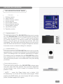
version 1.0
THANK YOU
Thank you for choosing Analog Way and the ORCHESTRA. By following these simple steps,
you should be able to setup and use your powerful remote controller within minutes. Discover the
ORCHESTRA’s extensive capabilities and intuitive interface while configuring your first show, and,
in combination with the all new Opus, Opus LE*, Pulse*, Pulse LE*, SmartVu*, SmartVu LE* or
Di-VentiX II, unleash all your creativity for a new experience in show and event management by
Analog Way.
TABLE OF CONTENTS
1
INTRODUCTION
6
WHAT IS THE ORCHESTRA
6
USEFUL TERMS AND DEFINITIONS
6
Screens
Presets
Layers
Frames & Backgrounds
PIP (Picture In Picture)
Logos
Keying & Titling
ORCHESTRA COLOR CODES
HARDWARE INSTALLATION
7
8
SAFETY PRECAUTIONS
8
UNPACKING AND INSPECTION
13
THE ORCHESTRA REAR PANEL
13
HARDWARE SPECIFICATIONS
14
1
ORCHESTRA OVERVIEW
THE ORCHESTRA FRONT PANEL
15
15
Overview
Settings section
Layout section
Preset Memory section
Screen section
Source Main section
Source Preview section
Preset Edition section
User Effect section
Transition section
STARTING WITH THE ORCHESTRA
OPERATIONAL CONFIGURATION
18
18
User configuration
System configuration
Show configuration
SHOW SETTINGS
Screen setup
Edit devices
Output configuration
Video Out configuration
Input configuration
Audio configuration
Source configuration
Soft Edge setup
Image settings
Logos & Frames configuration
Controls menu
2
20
OPERATING THE ORCHESTRA
USING THE JOYSTICK
27
27
Position
Size
Zoom
LAYER SETTINGS
27
Layer Settings
Element Settings
Source Settings
LIVE BACKGROUNDS
29
Adding a Live Background
Clearing a Live Background
FRAME BACKGROUNDS
29
Adding a Frame Background
Clearing a Frame Background
WORKING WITH PIPs
30
Selecting a PIP
Adding a PIP
Manipulating a PIP
PIP depth
Clearing a PIP
Clearing all PIPs
WORKING WITH LOGOS
33
Selecting a logo
Adding a logo
Manipulating a logo
Logo depth
Clearing a logo
Clearing all logos
3
PRESET MEMORIES
34
Saving a Preset Memory
Loading a Preset Memory
Reloading Memory From Main
Accessing Memory pages
TRANSITIONS
36
User Effects
Take
T-Bar
Step back (toggle)
Take Cut
WORKING WITH A MATRIX
MATRIX SETUP
38
MATRIX CONFIGURATION
38
APPLICATION NOTES AND TIPS
40
ABOUT APPLICATION NOTES
40
APPLICATION NOTES
41
SOFT EDGE BLENDING
SOFT EDGE BLENDING
Soft Edge setup
4
38
44
44
WARRANTY AND SERVICES INFORMATION
46
ANALOG WAY LIMITED WARRANTY
46
SERVICES AND RMA
46
CONTACT INFORMATION
HOW TO CONTACT US
47
47
After sales services
Analog Way offices worldwide
Regional contact information
Analog Way website
5
INTRODUCTION
WHAT IS THE ORCHESTRA
ORCHESTRA is a powerful intuitive and ergonomic remote controller designed to manage several
switchers such as Di-VentiX II, Opus, Opus LE*, Pulse*, Pulse LE*, SmartVu* and SmartVu LE*
systems, independently or simultaneously in any kind of combination, including Soft Edge Blending.
ORCHESTRA can control up to 6 independent screen configurations in different locations (single
display or multiple projectors in Soft Edge Blending mode) and store up to 64 presets per screen
configuration. ORCHESTRA controls the effects and functionalities of the Di-VentiX II and Opus,
Opus LE*, Pulse*, Pulse LE*, SmartVu* and SmartVu LE* systems.
* NOTE * : ORCHESTRA offers the control of matrices in order to multiply the number of live
sources, whatever the Analog Way switcher number of inputs is.
Designed with a 16/9 TFT color tactile screen for easy preview of all configurations, ORCHESTRA
is especially dedicated to facilitate setting up and programming of multi-screen events and
presentations. It perfectly fits your every day or prestigious shows where quickness and easiness
of configuration are required.
The numerous user friendly, customizable and configurable presets enable the set up of your screen
configuration, so that they are easily accessible during the presentation. Any last minute modification
is easy thank to the direct input/output selection access. Also equipped with a USB port, the complete
configuration of your events can be saved for future use.
With its new Interface Human Machine, ORCHESTRA will help to manage multi-screen and multilocation live presentations with total peace of mind.
USEFUL TERMS AND DEFINITIONS
SCREENS : a Screen on the ORCHESTRA is a containing element, which corresponds to a
projection surface. A Screen generaly contains a device, such as a Di-VentiX II, an Opus, Opus
LE*, Pulse*, Pulse LE*, SmartVu* or SmartVu LE* though a screen could well be composed of
several devices, in Soft Edge configuration for example.
PRESET : a preset on the ORCHESTRA, is a capture (or a recall) of the state of a Screen. In other
words, presets allow to record or recall the state of sources and elements in a Screen at any given
moment.
LAYERS : a “Layer” is an image display element (such as a Background, a PIP, or a Logo) that
has an associated visual priority — either in front (or in back) of another layer.
BACKGROUND FRAME : a Background Frame is a full screen image which is selected from one
of the 8 memory slots available in the Di-Ventix II, OPUS, Opus LE*, Pulse*, Pulse LE*, SmartVu*
or SmartVu LE* . A Frame can be flash captured from any video or computer source plugged into
the machine.
BACKGROUND LIVE : a Background Live is a live (animated video or motion content) full screen
image which is selected from one of the available sources of the slave device.
* Available in January 2010
6
PIP : a “PIP” refers to Picture-in-Picture. It is a source (typically of reduced size) that
is positioned over another background image or another PIP. PIPs can be reduced, enlarged,
bordered and shadowed. They can overlap one another, depending on their visual priority.
LOGO : a “Logo” is a part of an image that can be flash captured from any video or computer source,
by keying or image cut-out. Logos can be positioned.
KEYING & TITLING : a “Key” is an electronic process whereby an image is electronically superimposed
over another source or background by masking out either a color (chroma key), or a luminance level
(Luma Key) . Keys are typically used for titles, logos and special effects.
ORCHESTRA COLOR CODES
The ORCHESTRA buttons were designed with a handy color code to guide users, avoid mistakes,
and give a constant status of the device. Thus, all ORCHESTRA buttons have two or three different
states (and colors), depending on their function and their current state.
All available (selectable) buttons, functions and effects light up green, other than the Source Main
buttons which light up in red when available.
Any selected button on the ORCHESTRA turns a strong yellow.
The TAKE button is indicated in red, and will blink red when active.
The ORCHESTRA is comprised of several double-take buttons (CLEAR, CLEAR PIPs, CLEAR
LOGOs, CLEAR ALL buttons...) which should be pressed once to activate and a second time to
confirm. These will blink yellow while waiting for confirmation.
Finally, some of the ORCHESTRA buttons (SOURCE PREVIEW for example) will turn pale yellow
when they have been selected, are active, but are not currently being worked with.
7
HARDWARE INSTALLATION
SAFETY PRECAUTIONS
All of the safety and operating instructions should be read before the product is operated and should
be maintained for further reference. Please follow all of the warnings on this product and its operating
instructions.
WARNING : To prevent the risk of electric shock and fire, do not expose this device to rain, humidity,
intense heat sources (such as heaters and direct sunlight). Slots and openings in the device are
provided for ventilation and to avoid overheating. Make sure the device is never placed near a textile
surface that could block the openings. Also keep away from excessive dust, vibrations and shocks.
POWER : Only use the power supply indicated on the device of the power source. Devices equipped
with a grounding plug should only be used with a grounding type outlet. In no way should this
grounding be modified, avoided or suppressed.
POWER CORD : The device is equipped with a main switch (On (I) /Off (O)). The Switch ON and
OFF is initiated by the main switch.
Caution: The power cord constitute the only mean to totaly disconnect the equipment from the main
power.
Apply the following guidelines:
- The equipment connected to the network must have a release system easily accessible and located
outside the unit.
- Unplug the power cord, do not pull on the power cord but always on the plug itself.
- The outlet should always be near the device and easily accessible.
- Power supply cords should be routed so that they are not likely to be walked on or pinched by items
placed upon or against them.
If the power supply cord is damaged, unplug the device. Using the device with a damaged power
supply cord may expose your device to electric shocks or other hazards. Verify the condition of
the power supply cords once in a while. Contact your dealer or service center for replacement if
damaged.
CONNECTIONS : All inputs and outputs (except for the power input) are TBTS defined under
EN60950.
SERVICING : Do not attempt to service this product yourself by opening or removing covers and
screws since it may expose your device to electric shocks or other hazards. Refer all problems to
qualified service personnel.
OPENINGS : Never push objects of any kind into this product through the openings. If liquids have
been spilled or objects have fallen into the device, unplug it immediately and have it checked by a
qualified technician.
8
INSTRUCTIONS DE SÉCURITÉ
Afin de mieux comprendre le fonctionnement de cet appareil nous vous conseillons de bien lire
toutes les consignes de sécurité et de fonctionnement de l’appareil avant utilisation. Conserver les
instructions de sécurité et de fonctionnement afin de pouvoir les consulter ultérieurement. Respecter
toutes les consignes marquées dans la documentation, sur le produit et sur ce document.
ATTENTION : Afin de prévenir tout risque de choc électrique et d’incendie, ne pas exposer cet
appareil à la pluie, à l’humidité et aux sources de chaleur intense.
INSTALLATION : Veillez à assurer une circulation d’air suffisante pour éviter toute surchauffe à
l’intérieur de l’appareil. Ne placez pas l’appareil sur ou à proximité d’une surface textile susceptible
d’obstruer les orifices de ventilation. N’installez pas l’appareil à proximité de sources de chaleur
comme un radiateur ou une poche d’air chaud, ni dans un endroit exposé au rayonnement solaire
direct, à des poussières excessives, à des vibrations ou à des chocs mécaniques. Ceci pourrait
provoquer un mauvais fonctionnement et un accident.
ALIMENTATION : Ne faire fonctionner l’appareil qu’avec la source d’alimentation indiquée sur
l’appareil. Les appareils doivent être obligatoirement connectés sur une source équipée d’une mise à
la terre efficace. En aucun cas cette liaison de terre ne devra être modifiée, contournée ou supprimée.
CORDON D’ALIMENTATION : Les appareils sont équipés d’un interrupteur général (Marche I / Arrêt
O), la mise en tension et la mise hors tension se fait en actionnant cet interrupteur général. Attention :
Le cordon d’alimentation constitue le seul moyen de débrancher l’appareil totalement de l’alimentation
secteur. Pour être certain que l’appareil n’est plus alimenté, ce cordon doit être débranché de la prise
murale.
Appliquer les consignes suivantes :
- Le matériel relié a demeure au réseau, doit avoir un dispositif de sectionnement facilement accessible
qui doit être incoporé à l’extérieur de l’appareil.
- Débrancher le cordon d’alimentation de la prise murale si vous prévoyez de ne pas utiliser l’appareil
pendant quelques jours ou plus.
- Pour débrancher le cordon, tirez le par la fiche. Ne tirez jamais sur le cordon proprement dit.
- La prise d’alimentation doit se trouver à proximité de l’appareil et être aisément accessible.
- Ne laissez pas tomber le cordon d’alimentation et ne posez pas d’objets lourds dessus.
Si le cordon d’alimentation est endommagé, débranchez le immédiatement de la prise murale. Il
est dangereux de faire fonctionner un appareil avec un cordon endommagé, un câble abîmé peut
provoquer un risque d’incendie ou un choc électrique. Vérifier le câble d’alimentation de temps en
temps. Contacter votre revendeur ou le service après vente pour un remplacement.
CONNEXIONS : Toutes les entrées et sorties (exceptée l’entrée secteur) sont de type TBTS (Très
Basse Tension de Sécurité) définies selon EN 60950.
RÉPARATION ET MAINTENANCE : L’utilisateur ne doit en aucun cas essayer de procéder aux
opérations de dépannage, car l’ouverture des appareils par retrait des capots ou de toutes autres
pièces constituant les boîtiers ainsi que le dévissage des vis apparentes à l’extérieur, risque
d’exposer l’utilisateur à des chocs électriques ou autres dangers. Contacter le service après vente
ou votre revendeur ou s’adresser à un personnel qualifié uniquement.
OUVERTURES ET ORIFICES : Les appareils peuvent comporter des ouvertures (aération, fentes,
etc...), veuillez ne jamais y introduire d’objets et ne jamais obstruer ses ouvertures. Si un liquide ou
un objet pénètre à l’intérieur de l’appareil, débranchez immédiatement l’appareil et faites le contrôler
par un personnel qualifié avant de le remettre en service.
18
9
INSTRUZIONI DI SECUREZZA
Allo scopo di capire meglio il funzionamento di questa apparecchiatura vi consigliamo di leggere
bene tutti i consigli di sicurezza e di funzionamento prima dell’utilizzo. Conservare le istruzioni di
sicurezza e di funzionamento al fine di poterle consultare ulteriormente. Seguire tutti i consigli
indicati su questo manuale e sull’apparecchiatura.
ATTENZIONE : Al fine di prevenire qualsiasi rischio di shock elettrico e d’incendio, non esporre
l’apparecchiatura a pioggia, umidità e a sorgenti di eccessivo calore.
INSTALLAZIONE : Assicuratevi che vi sia una sufficiente circolazione d’aria per evitare qualsiasi
surriscaldamento all’interno dell’apparecchiatura. Non collocare l’apparecchiatura in prossimità
o su superfici tessili suscettibili di ostruire il funzionamento della ventilazione. Non installate
l’apparecchiatura in prossimità di sorgenti di calore come un radiatore o una fuoruscita d’aria calda,
né in un posto esposto direttamente ai raggi del sole, a polvere eccessiva, a vibrazioni o a shock
meccanici. Ció potrebbe provocare un erroneo funzionamento e un incidente.
ALIMENTAZIONE : Far funzionare l’apparecchiatura solo con la sorgente d’alimentazione indicata
sull’apparecchiatura. Le apparecchiature queste devono essere obbligatoriamente collegate su una
sorgente fornita di una efficiente messa a terra. In nessun caso questo collegamento potrà essere
modificato, sostituito o eliminato.
CAVO DI ALIMENTAZIONE : Gli apparecchi con un interrutore (commutatore) generale (Accesso I:
Speuto 0), accendere ou spagnere l’apparecchio si fa usando l’interrutore.
Attenzione : il cavo di alimentazione è il solo modo di disconnettere l’apparecchio dell’alimentazione.
Per assicurarsi che totalemente l’apparecchio non è più collegato, il cavo deve essere disconesso
della presa murale.
Seguire le instruzioni seguenti :
- Il materiale collegato a residenza alla rete, deve avere un dispositivo di sezionamento facile da
raggiongere eche deve essere inserito all’esterno del apparecchio.
- Disconnettere l’apparecchiatura dalla presa murale se si prevede di non utilizzarla per qualche
giorno.
- Per disconnettere il cavo tirare facendo forza sul connettore.
- La presa d’alimentazione deve trovarsi in prossimità dell’apparecchiatura ed essere facilmente
accessibile.
- Non far cadere il cavo di alimentazione né appoggiarci sopra degli oggetti pesanti.
Se il cavo di alimentazione é danneggiato, spegnere immediatamente l’apparecchiatura. E’ pericoloso
far funzionare questa apparecchiatura con un cavo di alimentazione danneggiato, un cavo graffiato
puó provocare un rischio di incendio o uno shock elettrico. Verificare il cavo di alimentazione spesso.
Contattare il vostro rivenditore o il servizio assistenza per una sostituzione.
CONNESSIONE : Tutti gli ingressi e le uscite (eccetto l’alimentazione) sono di tipo TBTS definite
secondo EN 60950.
RIPARAZIONI E ASSISTENZA : L’utilizzatore non deve in nessun caso cercare di riparare
l’apparecchiatura, poiché con l’apertura del coperchio metallico o di qualsiasi altro pezzo costituente
la scatola metallica, nonché svitare le viti che appaiono esteriormente, poiché ció puó provocare
all’utilizzatore un rischio di shock elettrico o altri rischi.
APERTURE DI VENTILAZIONE : Le apparecchiature possono comportare delle aperture di
ventilazione, si prega di non introdurre mai oggetti o ostruire le sue fessure. Se un liquido o un
oggetto penetra all’interno dell’apparecchiatura, disconnetterla e farla controllare da personale
qualificato prima di rimetterla in servizio.
10
SICHERHEITSHINWEISE
Um den Betrieb dieses Geräts zu verstehen, raten wir Ihnen vor der Inbetriebnahme alle Sicherheits
und Betriebsanweisungen genau zu lesen. Diese Sicherheits- und Betriebsanweisungen für einen
späteren Gebrauch sicher aufbewahren. Alle in den Unterlagen, an dem Gerät und hier angegebenen
Sicherheitsanweisungen einhalten.
ACHTUNG : um jegliches Risiko eines Stromschlags oder Feuers zu vermeiden, das Gerät nicht
Regen, Feuchtigkeit oder intensiven Wärmequellen aussetzen.
EINBAU : Eine ausreichende Luftzufuhr sicherstellen, um jegliche Überhitzung im Gerät zu
vermeiden. Das Gerät nicht auf und in Nähe von Textiloberflächen, die Belüftungsöffnungen
verschließen können, aufstellen. Das Gerät nicht in Nähe von Wärmequellen, wie z.B. Heizkörper
oder Warmluftkappe, aufstellen und es nicht dem direkten Sonnenlicht, übermäßigem Staub,
Vibrationen oder mechanischen Stößen aussetzen. Dies kann zu Betriebsstörungen und Unfällen
führen.
STROMVERSORGUNG : Das Gerät nur mit der auf dem Gerät bezeichnete Stromquelle betreiben.
Gerät mit geerdeter Hauptstromversorgung muss an eine Stromquelle mit effizienter Erdung
angeschlossen werden. Diese Erdung darf auf keinen Fall geändert, umgangen oder entfernt
werden.
NETZKABEL: Da die Geräte über einen Hauptschalter (An I/ Aus 0) verfügen, erfolgt die
Stromversorgung und -unterbrechung über diesen Hauptschalter.
Achtung : Das Netzkabel stellt die einzige Möglichkeit dar, das Gerät vollständig vom Netzanschluss
zu trennen. Um sicherzustellen, dass das Gerät nicht mehr versorgt wird, muss dieses Kabel aus
der Netzsteckdose ausgesteckt werden.
Bitte beachten Sie die folgenden Hinweise :
- Wenn Geräte dauerhaft am Netz bleiben, müssen sie über eine leicht zugängliche Trennvorrichtung
verfügen, die außen am Gerät angebracht sein muss.
- Das Kabel mittels dem Stecker herausziehen. Niemals am Stromkabel selbst ziehen.
- Die Steckdose muß sich in der Nähe des Geräts befinden und leicht zugänglich sein.
- Das Stromkabel nicht fallen lassen und keine schweren Gegenstände auf es stellen.
Wenn das Stromkabel beschädigt ist, das Gerät sofort abschalten. Es ist gefährlich das Gerät mit
einem beschädigten Stromkabel zu betreiben; ein abgenutztes Kabel kann zu einem Feuer oder
Stromschlag führen. Das Stromkabel regelmäßig untersuchen. Für den Ersatz, wenden Sie sich an
Ihren Verkäufer oder Kundendienststelle.
ANSCHLÜSSE : Bei allen Ein- und Ausgängen (außer der Stromversorgung) handelt es sich,
gemäß EN 60950, um Sicherheits Kleinspannunganschlüsse.
REPARATUR UND WARTUNG : Der Benutzer darf keinesfalls versuchen das Gerät selbst zu
reparieren, die Öffnung des Geräts durch Abnahme der Abdeckhaube oder jeglichen anderen
Teils des Gehäuses sowie die Entfernung von außen sichtbaren Schrauben zu Stromschlägen
oder anderen Gefahren für den Benutzer führen kann. Wenden Sie sich an Ihren Verkäufer, Ihre
Kundendienststelle oder an qualifizierte Fachkräfte.
ÖFFNUNGEN UND MUNDUNGEN : Die Geräte können über Öffnungen verfügen (Belüftung,
Schlitze, usw.). Niemals Gegenstände in die Öffnungen einführen oder die Öffnungen verschließen.
Wenn eine Flüssigkeit oder ein Gegenstand in das Gerät gelangt, den Stecker herausziehen und es
vor einer neuen Inbetriebnahme von qualifiziertem Fachpersonal überprüfen lassen.
11
18
INSTRUCCIONES DE SEGURIDAD
Para comprender mejor el funcionamiento de este aparato, le recomendamos que le acuidadosamente
todas las consignas de seguridad y de funcionamiento del aparato antes de usarlo. Conserve las
instrucciones de seguridad y de funcionamiento para que pueda consultarlas posteriormente.
Respete todas las consignas indicadas en la documentación, relacionadas con el producto y este
documento.
CUIDADO : Para prevenir cualquier riesgo de choque eléctrico y de incendio, no exponga este
aparato a la lluvia, a la humedad ni a fuentes de calorintensas.
INSTALACIÓN : Cerciórese de que haya una circulación de aire suficiente para evitar cualquier
sobrecalentamiento al interior del aparato. No coloque el aparato cerca ni sobre una superficie textil
que pudiera obstruir los orificios de ventilación. No instale el aparato cerca de fuentes de calor como
radiador o boca de aire caliente, ni en un lugar expuesto a los rayos solares directos o al polvo
excesivo, a las vibraciones o a los choques mecánicos. Esto podría provocar su mal funcionamiento
o un accidente.
ALIMENTACIÓN : Ponga a funcionar el aparato únicamente con la fuente de alimentación que se
indica en el aparato. Los aparatos deben estar conectados obligatoriamente a una fuente equipada
con una puesta a tierra eficaz. Por ningún motivo este enlace de tierra deberá ser modificado,
cambiado o suprimido.
CABLE DE ALIMENTACIÓN : Los equipos incluyan interruptor general de alimentación (Encender
I / Apagar 0), la puesta en marcha o desconexión se realiza por medio de este interruptor.
El cable de alimentación constituye el único medio de desconectar el aparato totalmente de la red
eléctrica. Para estar seguro de que el aparato no está más alimentado, este cable debe de ser
desconectado de la toma de corriente.
Aplicar las siguientes consignas:
- El material conectado a residencia a la red informática, debe de tener un dispositivo de
seccionamiento fácilmente accesible que debe de ser incorporado al exterior del aparato.
- Desconectar el aparato del enchufe mural si no piensa utilizarlo durante varios días.
- Para desconectar el cable, tire de la clavija. No tire nunca del cable propiamente dicho.
- El enchufe de alimentación debe estar cerca del aparato y ser de fácil acceso.
- No deje caer el cable de alimentación ni coloque objetos pesados encima de él.
Si el cable de alimentación sufriera algún daño, ponga el aparato inmediatamente fuera de tensión.
Es peligroso hacer funcionar este aparato con un cable averiado, ya que un cable dañado puede
provocar un incendio o un choque eléctrico. Verifique el estado del cable de alimentación de vez en
cuando. Póngase en contacto con su distribuidor o con el servicio de posventa si necesita cambiarlo.
CONEXIONES : Todas las entradas y salidas (excepto la entrada del sector) son de tipo TBTS (Muy
Baja Tensión de Seguridad) definidas según EN 60950
REPARACIÓN Y MANTENIMIENTO : Por ningún motivo, el usuario deberá tratar de efectuar
operaciones de reparación, ya que si abre los aparatos retirando el capó o cualquier otra pieza
que forma parte de las cajas o si destornilla los tornillos aparentes exteriores, existe el riesgo de
producirse una explosión, choques eléctricos o cualquier otro incidente. Contacte el servicio de
posventa, a su distribuidor o dirigirse con personal cualificado únicamente.
ABERTURAS Y ORIFICIOS : Los aparatos pueden contener aberturas (aireación, ranuras, etc.).
No introduzca allí ningún objeto ni obstruya nunca estas aberturas. Si un líquido o un objeto penetra
al interior del aparato, desconéctelo y hágalo revisar por personal cualificado antes de ponerlo
nuevamente en servicio.
12
UNPACKING AND INSPECTION
When unpacking your ORCHESTRA, please mind not to discard product packaging, as the removable
feet and the rackmount ruler and screws are in the packing foam of the device.
1 x ORCHESTRA remote controller
1 x Power supply cord
1 x Quick Start guide
1 x User manual
1 x Rack mount ruler and screws
2 x Adjustable feet
THE ORCHESTRA REAR PANEL
1 - On/Off switch
2 - AC Connector
3 - Serial Ports (not in use)
4 - Ethernet Port
5 - Auxiliary Ethernet Port (not in use, black caps)
6 - Auxiliary Display output
7 - Rackmount rule
13
18
HARDWARE SPECIFICATIONS
Dimensions : W 450 x D 440 x H 180 mm
17.8”W x 17.5”D x 7.1”H.
Weight :
9 kg / 19.8 lbs.
Cooling air flow from right side to left side.
Maximum ambient operating temperature : < 40 °C ( < 104°F).
Operating temperature : 0 to 40 °C / +32 ° to +104 °F
Storage temperature : -25 to 85 °C / -13° to +185 °F
Operating humidity : 10 to 80% (non condensing)
Input voltage range : 100-240 VAC, 50/60 Hz
Typical consumption : 50 W
CE Compliancy, test following :
- EN 55022: 2006 / A1 : 2007,
- EN 55024: 1998 / A1 : 2001 / A2 : 2003,
- EN 61000-3-2: 2006
- EN 61000-3-3: 1995 / A1 : 2001 / A2 : 2005,
Safety : test following :
- IEC 60950-1:2005
- UL 60950-1: 2007
- CAN/CSA-C22.2 NO. 60950-1
Power supply : IEC/EN/UL/CSA 60950-1, internal, autoswitchable
Mechanical (in carton) : Vibration : IEC60068-2-64
Free fall : IEC60068-2-32
RoHS, WEEE
14
ORCHESTRA OVERVIEW
THE ORCHESTRA FRONT PANEL
Overview
1 - Settings section
2 - Layout section
3 - Preset memory section
4 - Screen section
5 - Source Main section
6 - Source Preview section
7 - Preset Edition section
8 - User Effect section
9- Transition section
Settings section
The settings section of the ORCHESTRA allows you to access
all of the ORCHESTRA menus and functionalities quickly and
easily. The color widescreen 7” inch TFT tactile screen will give
you intuitive access to the device’s setup and configuration
menus, and will guide you through the process with clear
messaging. The 4 top rotative knobs will allow you to set values,
while the last knob will allow to navigate through the interface,
to access source or element settings for example.
Layout section
The Layout section of the ORCHESTRA allows users to quickly
access position, size and zoom settings for any adjustable layer
(PIPs, Live Backgrounds, and position parameters for Logos).
The settings can be changed with the ORCHESTRA joystick,
then memorized into one of the three available quick-access
user position/size presets, to be called back at any time during
your show.
Preset memory section
The preset memory section of the ORCHESTRA is where users
may save and recall their presets. Any on-screen disposition
can be stored to one of the 8 pages of 8 presets (64 user
presets in total).
* NOTE * : press the Page button and a button (1-8)
simultaneously to access the 8 possible preset pages. When
pressing the PAGE button, the current page will light up strong
yellow, available pages will be green.
15
Screen section
The Screen section of the ORCHESTRA allows users to select
and edit screens. Screens on the ORCHESTRA contain all of
the settings and information of any given device connected
to the ORCHESTRA. In other words, any device connected
to, and piloted by the ORCHESTRA, becomes an individual
screen, though several Di-VentiX II in a Soft Edge setup can
be considered as a Screen.
Source Main section
The Source Main section of the ORCHESTRA allows users
to select and work with sources directly on the Main output
of the device connected to the ORCHESTRA. 3 pages with
8 live sources per page (24 sources in total) are available.
When working with Frames or Logos, 8 sources are available
Source Preview section
The Source Preview section of the ORCHESTRA allows users
to select and work with sources on the Preview output of the
device connected to the ORCHESTRA.3 pages with 8 live
sources per page (24 sources in total) are available. When
working with Frames or Logos, 8 sources are available (1
Preset Edition section
The Preset Edition section of the ORCHESTRA is the true
operations center of the machine, and will give users instant
access to all of the functions needed to properly manage your
events and shows.
The Preset Edition section of the ORCHESTRA is the place
where users can manipulate, store, erase, or modify all
elements on screen. Here you can create, use, and rearrange
PIPs, logos and frames, create, store and recall user presets,
or simply toggle Main and Preview source selection amongst
other features.
User Effect section
The User Effect section of the ORCHESTRA gives users quick
access to basic image transitions via the Cut, Fade and Slide
buttons, and allows to create, store and recall layer transitions
as presets via the 3 handy User Effect buttons.
16
Transition section
The Transition section of the ORCHESTRA will allow you to
go live with whatever image, logo or PIP settings or changes
you have made on your preview screen. The Transition section
of the ORCHESTRA is also comprised of a Take Cut button,
for instant transitions from Preview to Main, and a handy Step
Back button, to toggle from Main back to Preview. The smooth
T-bar of the ORCHESTRA will glide from Preview to Main for
elegant transitions.
17
STARTING WITH THE ORCHESTRA
OPERATIONAL CONFIGURATION
User configuration
When the ORCHESTRA starts up, the User page will be
displayed over the Home page. Here, you can determine
whether to create a new user to work as, or use an already
existing one. The first time you use the ORCHESTRA, you will
have to create a new user.
1/ Press the New User button on the TFT screen.
2/ The ORCHESTRA will display the User Edit screen, which
allows you to name the new user according to your wishes.
When you have chosen a user name, press the OK button
to validate your choice. Press OK again if you do not wish to
create a password for the new user. Otherwise, enter a user
password which will be asked every time you wish to log in as
that user.
3/ On the User page, choose the user you have just created,
and press the OK button again. The ORCHESTRA will display
its home page.
System configuration
The ORCHESTRA System Configuration page allows you to
parameter the IP address of the ORCHESTRA, caliber the
joystick, the keyboard luminosity of the machine, set the time,
or check the software version and update it via the USB port if
need be.
1/ Press the System button on the TFT screen. The
ORCHESTRA will display the network configuration page of
the System menu.
2/ Rotate the corresponding knobs to change the IP address
of the ORCHESTRA (IP1, IP2, IP3, IP4) then press the OK
button to validate. A message will appear asking for you to wait
while the ORCHESTRA registers the new address, and asks
to reboot. Press Yes, and wait for reboot.
* NOTE * : the ORCHESTRA must be in the same network as
the devices it is going to control.
18
To configure keyboard brightness and parameter the
joystick :
1/ Press the Keyboard tab on the System Configuration page.
2/ Rotate the corresponding knob to increase/decrease
keyboard luminosity.
3/ Wriggle and turn the joystick, then let it return to its initial
position. If need be, press the Calibrate button which will adjust
the neutral position of the joystick precisely.
To set the time on the the ORCHESTRA :
1/ Press the Time tab on the System Configuration page.
2/ Change the time accordingly, by pressing the +/- buttons on
the onscreen clock.
To check and update firmware version of the ORCHESTRA:
1/ Press the Update tab on the System Configuration page.
2/ You can update the software by plugging a USB key with
an up to date version of the software on the front panel of the
ORCHESTRA. Press Refresh to list available update files on
the USB key and select the desired update from the list then
press Update. The ORCHESTRA will display a message while
it loads the new sofware.
* IMPORTANT * : do not remove the USB key during the update
process is in progress.
Show configuration
For the ORCHESTRA to start piloting your external device(s),
you must create a show to work in. The show will hold
parameters for any connected device (as well as all other show
parameters such as inputs, outputs, screens, presets...).
1/ Press the Shows button on the TFT screen, then press
Create a New Show.
2/ The ORCHESTRA will display the Show Edit screen, which
allows you to name the new show according to your wishes.
When you have chosen a show name, press the OK button to
validate your choice. The ORCHESTRA will display a blank
show page.
19
SHOW SETTINGS
Screen setup
For the ORCHESTRA to pilote external devices, they must be
set up as Screens. To setup a Screen, do the following :
1/ Select the next available screen (1-6) in the Screen section of
the ORCHESTRA. The Screen button will light up yellow, and a
display of your empty screen will appear on the ORCHESTRA
tactile screen.
2/ On the ORCHESTRA tactile screen, press Screen Setup to
enter the Screen configuration page, then press Edit if you wish
to give your Screen a different name than the default name
(Screen 1-6). Change the name of your Screen accordingly,
and press the OK button to validate and return to the Screen
Setup page.
Edit devices
To add a device into a Screen, activate it, and start piloting it,
do the following :
1/ In the Type dropdown menu on the tactile screen, select the
kind of device you want to use in your Screen (in this case a
Di-VentiX II).
2/ In the Mode dropdown menu on the tactile screen, select the
mode you want to use the device in (in this case Mixer Mode).
* NOTE * : Screen parameters other than Edit Devices will not
be available until a device is stored into a Screen and activated.
3/ Press Edit Devices, and press Add, the tactile screen will
display a page which will let you choose the device you want
the ORCHESTRA to pilote. Press Edit to give the device a
different name than the default name, select the communication
protocol the device is configured in, and change LAN settings
if need be.
* NOTE * : make sure LAN settings match those of your device.
* NOTE * : only TCP and UDP protocols are supported on the
ORCHESTRA. We recommend sticking to the TCP protocol.
20
4/ Press the OK button to confirm and return to the Devices
page. The ORCHESTRA will connect to the device. Press the
OK button to return to the Screen Setup page.
* NOTE * : Screen parameters should all be available now that
a device is activated in the current Screen.
Output configuration
Once your device has been added into a Screen, you can
configure its outputs.
1/ On the Screen Setup page of the ORCHESTRA, press Edit
Outputs.
2/ Select the output, Main or Preview you wish to configure,
then select the output format (resolution), output rate, output
type as needed.
3/ Press Pattern, and select a pattern from the dropdown menu
to check your output settings are properly configured. When
you are satisfied, press Pattern again, and choose none to
revert to your image on screen.
Video Out configuration
The Video Out tab will be available only if the slave device has
an optional video card installed (for example a Di-VentiX II with
option VO-8044).
1/ In the Screen Setup page of the ORCHESTRA, press Edit
Video Out.
2/ Select the display mode for the slave device video out card,
then select the output format (resolution), output rate, and
signal type.
3/ Press Pattern to generate a pattern on the screen/device
plugged to the slave device video out card if you wish to check
the video Out setup.
4/ Press the OK button to confirm and return to the Screen
Setup page.
21
Input configuration
To properly synchronize the slave device with your
ORCHESTRA, you must setup the inputs of the device into the
ORCHESTRA.
1/ In the Screen Setup page of the ORCHESTRA, press Edit
Inputs.
2/ Select the input you wish to parameter, then select the plug
type, and the type of signal. The status box (by the Select Input
dropdown menu) should display image resolution and rate.
* NOTE * : if you are working with a matrix, you can route your
image through the matrix via the dropdown Linked To Matrix
and Matrix Output tabs (see also Working With a Matrix, p.38).
3/ Press the OK button to confirm input settings and return to
the Screen Setup page.
Audio configuration
The Audio Edit tab will give access to audio in/out parameters
such as levels, balance or volume. This feature is not
implemented at the moment.
Source configuration
The Edit Sources tab allows to map device inputs, logos or
frames to source buttons on the ORCHESTRA front panel.
1/ In the Screen Setup page of the ORCHESTRA, press Edit
Sources. The buttons in the Source Preview section of the
ORCHESTRA will light up, allowing you to select the source
you wish to work on.
2/ Select the source you wish to parameter, then press Edit to
give the source a new name if you wish.
* NOTE * : if you are working with a matrix, you can map matrix
inputs to sources, assuming you have defined links between
the matrix and your device in the Edit Inputs page (see the
Input Configuration chapter, p.22 and the Working With A
Matrix chapter, p.38).
3/ The Enable checkbox allows you to activate (default) or
de-activate sources. De-activating this button will result in an
inaccessible button on the ORCHESTRA front panel.
22
Soft Edge Setup
The Edit Soft Edge tab will be available only if the connected
slave device is being used in Embedded Soft Edge mode (for
example a Di-VentiX II).
* NOTE * : for more detail on Soft Edge Blending, please refer
to the Soft Edge Blending chapter of this manual, p.44.
1/ In the Screen Setup page of the ORCHESTRA, press Edit
Soft Edge.
2/ On the Soft Edge Setup page, you will find several tabs to
create, control and adjust your Soft Edge. Press on Soft Edge
Type to choose the type of Soft Edge to apply (horizontal or
vertical). You can also position the devices within the screen by
scrolling with the appropriate knob left or right.
3/ Press the Covering tab to control the amount of Soft
Edge covering you need (indicated in pixels). By rotating the
corresponding knob, increase (right) or decrease (left) the
amount of image covering on your Soft Edge.
4/ Press Black to adjust the levels of black for your Soft Edge.
On the Black tab, select the slave device you wish to work on,
and rotate the corresponding knobs to determine black levels
for your Soft Edge.
5/ Press the Blending tab to fine tune your Soft Edge.
Select a device in the dropdown menu, then, by rotating
the corresponding knobs, position the X and Y points of the
Blending curve, and increase or decrease their values to obtain
the desire onscreen balance for your Soft Edge.
6/ Press Pattern to go to the Patterns tab, and select the
appropriate patterns to create, setup and fine tune your Soft
Edge image. Choose amongst None, V. (vertical) Grey Scale, H.
(horizontal) Grey Scale, V (vertical) Color Bars, H. (horizontal)
Color Bars, Grid, SMPTE, Burst, Centering and Covering.
* NOTE * : to configure your Soft Edge properly, you will probably
need to generate several types of patterns. Some patterns are
dedicated to video projector setup (like Grid or Centering),
where others are designed to adjust image blending (like Burst
or Covering). Simply select the pattern you want to use at any
given stage, adjust your settings, and return to the Patterns tab
to change pattern for further adjustements, or to remove it from
your screen.
23
Image Settings
The Image Settings page allows to fine tune the source image
of any input you have previously entered into your Screen. This
menu is accessible when working directly with live sources
on the ORCHESTRA front panel (for more detail on Image
Settings, please refer to the Layer Settings chapter, p.28).
1/ In the Screen Setup page of the ORCHESTRA, press Image
Settings. The Image Settings page will give access to different
settings depending on whether the selected source is a digital
or an analog source.
2/ Select the source you wish to work on. Buttons in the
Source Preview section will light up, indicating the sources are
available.
2/ Select the Adjust, Position/Size, Pulldown, Aspect Ratio,
Zoom or Keying tabs to adjust those settings of your source
image by rotating the corresponding knob, then sliding values
up or down to fine tune your source.
3/ When you are satisfied with your image settings, press the
OK button to return to the Screen Setup page.
Logos & Frames
The Logos/Frames page allows users to capture and store
logos and frames (see also Frame Background, p. 29).
1/ In the Screen Setup page of the ORCHESTRA, press Logos/
Frames. The buttons in the Source Preview section of the
ORCHESTRA will light up, allowing you to display the source
you wish to capture. The buttons in the Layout section and the
Settings section will also light up, and give you access to your
logo or frame parameters.
2/ Select the source you wish to capture by pressing a Source
Preview button (1-8), then select the Record Logo tab if you
wish to record a logo, or the Record Frame tab if you wish to
record a frame. In this case, we will see how to record a logo.
A white rectangle will appear on screen to indicate the area to
capture as a logo.
3/ Select the memory you wish to store the logo/frame into (1-8)
in the Memory Slot dropdown menu.
24
4/ In the Layout section, press the POS button, and with the
help of the joystick, move the rectangle on screen to the area
where your logo is. Resize the container to fit the logo if need
be, by pressing the Size button then adjusting with the joystick.
* NOTE * : to move the source, rather than the container
rectangle itself, press Source rather than Logo on the Position/
Size Adjust panel, and adjust size and position with the help of
the joystick as described in step 4.
5/ With the help of the corresponding knobs, slide values up or
down to set luma key parameters for your logo.
* NOTE * : as Frames do not handle keying, the Record Frames
tab does not give access to keying parameters.
6/ Once all your logo parameters are set, press Store. The
ORCHESTRA will display a progress status bar while the
device memorizes the logo.
7/ Press the OK button to return to the Screen Setup page.
* NOTE * : to record a logo in Soft Edge Blending Mode, you
need to press Source in the Position/Size Adjust panel, then
press Extended.
Controls Menu
The Controls page allows users to select the Tally trigger on the
slave device. The Controls page also allows to reset a device
to its default values, or erase all image settings present on the
device.
To setup a tally signal with the ORCHESTRA :
1/ On the Screen Setup page of the ORCHESTRA, press
Controls.
2/ Press one of the four available Tally dropdown menu to
select the source you want to use as a trigger.
3/ Press the OK button to return to the Screen Setup page.
To erase all image settings on the slave device :
1/ In the Screen Setup page of the ORCHESTRA, press
Controls.
25
2/ Press Erase Memories.
3/ Confirm by pressing Yes on the confirmation popup.
4/ Press the OK button to return to the Screen Setup page.
To reset all settings on the slave device :
1/ In the Screen Setup page of the ORCHESTRA, press
Controls.
2/ Press Default Values.
3/ Confirm by pressing Yes on the confirmation popup.
4/ Press the OK button to return to the Screen Setup page.
26
OPERATING THE ORCHESTRA
USING THE JOYSTICK
The joystick in the Layout section of the ORCHESTRA allows
users to move, resize or zoom any selected element on screen.
To use the joystick to position elements on screen, select an
element (logo, PIP...) and press the POS button, then, tilt the
joystick left to move the selected element left, tilt right to move
right, and so on.
To use the joystick to resize elements on screen, select an
element, and press the SIZE button. Tilt the joystick left to
scale it down horizontally, tilt right to scale it up. Tilt joystick up
and down to scale it vertically. You can also rotate the joystick
to scale elements up (clockwise) or down (counterclockwise)
both vertically and horizontally.
When using the joystick to zoom elements on screen, select an
element and press the ZOOM button. When the ZOOM button
is active, you can either zoom into your source, by pressing the
SIZE button then tilting the joystick left to zoom out, or right to
zoom in, and so on. Or, you can press the POS button, then
tilting the joystick in different directions moves the zoomed
source around in those directions inside the element.
LAYER SETTINGS
Layer Settings
Any selected layer (Frame, Live Background, PIP, Logo) on the
ORCHESTRA is represented graphically on the Settings section
tactile screen as a yellow rectangle container. Information on
the layer is written in the layer container rectangle for users
to access information quickly and intuitively. The selected
layer is composed of a container, called Element, which you
can access by pressing Element on the Preview page, and a
Source (image) which you can parameter by pressing Source
on the Preview page. The element or source settings can also
be accessed by turning the last knob of the Settings section
left or right.
Element Settings
To access the element settings of any selected layer (Frame,
Live Background, PIP, Logo) on the ORCHESTRA press
Element at the bottom of the Preview page, or turn the last
knob of the Settings section.
27
On the Element page, you will find a list of several accessible
tabs.
The Transition tab (default), which allows users to determine
how a layer comes into and goes out of your screen (cut, wipe,
fade...).
The Window tab, which will let users move and resize the
layer container.
The Zoom tab, which will let users zoom in and out of a source
and move it around within its layer.
The Border tab, which allows users to set layer border
parameters, such as border color, width or drop shadow
parameters.
The Transparency tab, which determines the opacity of a
layer.
The Element page also lets users save position and size
settings of any layer into 3 handy User Position/Size memories
which can be called back and edited at any stage.
To return to the Preview page, press Preset or turn the last
knob of the Settings section. Press Source to enter the Source
page, or turn the last knob of the Settings section.
Source Settings
To access the source settings of any selected layer (Frame,
Live Background, PIP, Logo) on the ORCHESTRA press
Source at the bottom of the Preview page, or turn the last knob
of the Settings section (the PRESET, ELEMENT and SOURCE
pages are in a page cycle, meaning you can access all three
pages by scrolling left or right).
On the Source page, you can edit the source name by pressing
Edit and entering a new name, or you can access the Image
Settings tab (see also Image Settings, p.24).
On the Image Settings tab, you will find a list of several
accessible settings, depending on the type of source you are
working on.
To return to the Preview page, press Preset or turn the last knob
of the Settings section. Press Element to enter the Element
page, or turn the last knob of the Settings section.
28
LIVE BACKROUNDS
Adding a background
To add a Live Background (motion content layer) to your empty
Preset, proceed as follows :
1/ Press the BKGND LIVE button to activate the Live
Background container rectangle on screen. The tactile screen
of the ORCHESTRA will display a yellow rectangle, indicating
the selected area, and your Preview output will display an
empty selection rectangle.
2/ The blue Source Preview section light will blink to indicate you
can select the source you want to use as a Live Background.
Press a Source Preview button (1-8). The chosen image should
now appear on your Preview output.
3/ Press the TAKE button to view the result on your Main output.
Clearing a background
To clear a Live Background from your Screen, proceed as
follows :
1/ Press the BKGND LIVE button to select the Live Background
you wish to clear from your Screen.
2/ Press the CLEAR button once. In the ORCHESTRA Settings
section, the tactile screen will ask to confirm in the form of a
message on a yellow banner at the bottom of the screen. Press
the CLEAR button again to confirm. The Live Background will
go to black on the Preview output.
3/ Select a new source for your empty Live Background by
pressing a Source Preview button (1-8), or simply press the
TAKE button to view the result on your Main output.
* NOTE * : you do not need to clear a background to switch its
source.
FRAME BACKGROUNDS
Adding a frame
To add a Frame (fixed content frame) to your empty Screen,
proceed as follows :
29
1/ Press the BKGND FRAME button to activate the Background
Frame container rectangle on screen. The tactile screen of the
ORCHESTRA will display a yellow rectangle, indicating the
selected area.
2/ The blue Source Preview section light will blink to indicate
you can select the source you want to use as a Background
Frame. Press a Source Preview button (1-8). The chosen
image should now appear on your Preview output.
3/ Press the TAKE button to view the result on your Main output.
Clearing a frame
To clear a Frame from your Screen, proceed as follows :
1/ Press the BKGND FRAME button to select the Background
Frame you wish to clear from your Screen.
2/ Press the CLEAR button once. In the ORCHESTRA Settings
section, the tactile screen will ask to confirm in the form of a
message on a yellow banner at the bottom of the screen. Press
the CLEAR button again to confirm. The Background Frame
will go to black on the Preview output.
3/ Select a new source for your empty Frame Background by
pressing a Source Preview button (1-8), or simply press the
TAKE button to view the result on your Main output.
* NOTE * : it is not necessary to clear a background frame to
switch its source.
WORKING WITH PIPs
Adding a PIP
To add a PIP (Picture In Picture) to your Screen, proceed as
follows:
1/ Press the ADD PIP button to activate the PIP container
rectangle on screen. The tactile screen of the ORCHESTRA
will display a yellow rectangle, indicating the PIP position and
size.
2/ The blue Source Preview section light will blink to indicate
you can select the source you want to use as a PIP. Press a
Source Preview button (1-8). The chosen image should now
30
appear on your Preview output in the PIP rectangle, and on
the tactile screen of the ORCHESTRA in the shape of a yellow
rectangle above any Frame or Live Background.
3/ Press the TAKE button to view the result on your Main output.
4/ To add another PIP, follow steps 1-3 again.
Selecting a PIP
To select the PIP you wish to work with, press several times on
the SELECT PIP button, or press on the PIP container on the
tactile screen of the ORCHESTRA.
Manipulating a PIP
PIPs on your Screen can be resized, positioned, users may
add borders, transparency and much more.
To position a PIP :
1/ Select the PIP you wish to move.
2/ In the Layout section, press the POS button, and move the
PIP with the help of the joystick (see also Using The Joystick,
p.27).
3/ When you have reached the desired position, press the
TAKE button to view the result on the Main output.
To resize a PIP :
1/ Select the PIP you wish to resize.
2/ In the Layout section, press the SIZE button, and resize the
PIP with the help of the joystick (see also Using The Joystick,
p.27).
3/ When you have resized your PIP, press the TAKE button to
view the result on the Main output.
To zoom into and out of a PIP :
1/ Select the PIP you wish to zoom in or out of.
2/ In the Layout section, press the ZOOM button, and adjust
the zoom in the PIP with the help of the joystick (see also Using
The Joystick, p.27).
31
3/ When you have set the PIP zoom, press the TAKE button to
view the result on the Main output.
To add a border to a PIP :
1/ Select the PIP you wish to add a border to.
2/ In the Preset Edition section, press the BORDER button to
access border settings displayed on the tactile screen of the
ORCHESTRA (see also Element Settings, p.27).
3/ Set border attributes in the PIP tab.
PIP depth
The PIP depth allows users to move PIPs up or down through
the successive layer hierarchy. In other words, you can change
the order of a PIP from under another PIP to over it, or viceversa.
1/ Select the PIP you want to move up or down.
2/ Press the LOWER button to move the PIP back in the order
of logos on screen, press the RAISE button to move the PIP
to front.
Clearing a PIP
To clear a PIP from your Screen, proceed as follows :
1/ Select the PIP you wish to clear.
2/ Press the CLEAR button once. In the ORCHESTRA Settings
section, the tactile screen will ask to confirm in the form of a
message on a yellow banner at the bottom of the screen. Press
the CLEAR button again to confirm. The PIP will disappear
from the Preview output.
3/ Press the TAKE button to view the result on your Main output.
* NOTE * : to clear all PIPs from your Screen, press the CLEAR
PIPs button rather than the CLEAR button.
32
WORKING WITH LOGOS
Adding a logo
To add a logo to your Screen, proceed as follows :
1/ Press the ADD LOGO button to activate the Logo container
rectangle on screen. The tactile screen of the ORCHESTRA
will display a yellow rectangle, indicating the logo size and
position.
2/ The blue Source Preview section light will blink to indicate
you can select the source you want to use as a logo. Press
a Source Preview button (1-8). The chosen logo should now
appear on your Preview output in the Logo rectangle, and on
the tactile screen of the ORCHESTRA in the shape of a yellow
rectangle above any Frame or live element.
3/ Press the TAKE button to view the result on your Main output.
4/ To add another logo, follow steps 1-3 again.
Selecting a logo
1/ To select the LOGO you wish to work with, press several
times on the SELECT LOGO button, or press on the LOGO
container on the tactile screen of the ORCHESTRA.
Manipulating a logo
Logos on your Screen can be positioned anywhere, and keying
attributes are available only during capture (see also Logos &
Frames, p.24).
To position a logo :
1/ Select the logo you wish to move.
2/ In the Layout section, press the POS button, and move the
logo with the help of the joystick (see also Using The Joystick,
p.27).
3/ When you have reached the desired position, press the
TAKE button to view the result on the Main output.
33
Logo depth
1/ Select the LOGO you wish to work to move up or down.
2/ Press the LOWER button to move the logo back in the order,
press the RAISE button to move the logo to front.
Clearing a Logo
To clear a Logo from your Screen, proceed as follows :
1/ Select the LOGO you wish to clear.
2/ Press the CLEAR button once. In the ORCHESTRA Settings
section, the tactile screen will ask to confirm in the form of a
message on a yellow banner at the bottom of the screen. Press
the CLEAR button again to confirm. The LOGO will disappear
from the Preview output.
3/ Press the TAKE button to view the result on your Main output.
* NOTE * : to clear all logos present on screen, in step 2, press
the CLEAR LOGOs button rather than the CLEAR button.
PRESET MEMORIES
Saving a Preset Memory
A Preset Memory can be viewed as a scene for you show or
event. In a Preset Memory, users store the setup and parameters
of all layers on a Screen to the ORCHESTRA memory. The
ORCHESTRA allows to save up to 64 Preset Memories per
Screen. To save a Preset Memory, proceed as follows :
1/ Configure all layers as desired in your Screen. Once this is
done, press the SAVE TO PRESET button in the Preset Edition
section of the ORCHESTRA.
2/ On the tactile screen of the ORCHESTRA, select the
Screen(s) (1-6) which you want to save as a Preset Memory.
3/ Select a memory slot by pressing button 1-8 in the Preset
Memory section.
34
Loading a Preset Memory
To call back an existing Preset Memory to use or start working
from at any stage during your show, proceed as follows :
1/ Press the LOAD FROM PRESET button to access the Preset
Memory page.
2/ On the tactile screen of the ORCHESTRA, select the screen
(1-6) which you wish to load from memory.
3/ Select a memory slot by pressing button 1-8 in the Preset
Memory section.
Reload Memory from Main
The ORCHESTRA allows for you to make a Preset Memory
from your Main output at any stage during your show (Reload
From Main will load Main output settings into your Preview
screen). To do this, proceed as follows :
1/ Press the RELOAD FROM MAIN button in the Preset Edition
section of the ORCHESTRA.
2/ Choose a Preset Memory to load your preset into.
3/ Press the RELOAD FROM MAIN button again to confirm
and return to your Preset page.
Accessing Memory pages
To access the 64 different Preset Memory slots available in the
ORCHESTRA, the 8 Preset Memory buttons can be used as
Preset Memory Page selection buttons by pressing the PAGE
button of the Preset Memory section of the ORCHESTRA.
1/ Press the PAGE button of the Preset Memory section and
simultaneously press button 1-8 to access Page#1- Page#8 of
the Preset Memories.
* NOTE * : Preset Memories 1-8 are on Page#1, 9-16 are on
Page#2, 17-24 are on Page#3 and so on.
* NOTE * : when you press the PAGE button, the selected page
will light up strong yellow. Other buttons of the section will stay
green.
35
TRANSITIONS
User Effects
With the ORCHESTRA, you can save the transition settings of
any layer into 3 handy User Effects which can be called back
and edited at any stage. To do this, proceed as follows :
1/ Select a layer and configure its in and out transitions via the
Element page.
2/ Once all the desired settings have been made, press Save To
User Effect 1 to store the settings into the User Effect memory.
3/ To recall the User Effect, press the USER EFFECT 1 button
in the Transition section of the ORCHESTRA. The User Effect
will appear as you have set it up on your Preview output.
4/ Press the TAKE button to view the result on your Main output.
Take
The TAKE button of the ORCHESTRA, allows users to bring
the Preview screen onto the Main screen. Typically, a user will
work on a preset on the Preview output, then switch that preset
to the Main output by pressing the TAKE button.
* NOTE * : The TAKE button is indicated in red, and will flash
when pressed indicating the switching process.
T-Bar
The handsome and smoothly weighted brushed aluminium
T-Bar of the ORCHESTRA, allows users to seamlessly bring
the Preview screen presets, to the Main output. Typically, a
user will work on a preset on the Preview output, then bring
that preset to the Main output by using the T-Bar.
* NOTE * : elegant transitions can be achieved using the T-Bar
by leaving it in the middle of its trajectory, resulting in Main
and Preview outputs overlapping. However, the ORCHESTRA
will not let you access any settings or changes on any layer or
source if the T-Bar has not completed its course.
36
* NOTE * : Taking between presets which exceed the slave
device’s ressources (too many layers for the device to handle
simultaneously) is called a Sequenced Take. Typically, in a
Sequenced Take, the device will execute all the closing effects
of layers which are not in the following preset. Then, it will
execute the cross effects of the layers common to both presets,
and finally execute the opening effects of the new layers in the
following preset. In this case, the T-Bar does not operate.
Step Back
The STEP BACK button in the ORCHESTRA Transition section,
allows users to literally go back one step. If you have made a
mistake in your Main output setup, and wish to revert to the
previous state, press the STEP BACK button, then press the
TAKE button, the ORCHESTRA will revert to the previous step.
* NOTE * : you can use the STEP BACK button as a way to
toggle between two presets. Simply press the STEP BACK
button and then the TAKE button as many times as you like,
thus switching back and forth between two presets.
Take Cut
The TAKE CUT button has exactly the same function as the
TAKE button, other than it overrides all transitions between
presets with a cut effect. For example, a PIP with a slide in
from left effect, will simply appear onscreen in its final position,
without executing the effect.
37
WORKING WITH A MATRIX
Matrix setup
If you are working with a matrix in your setup, you must add it
into your show. To do so, follow these few steps :
1/ On the ORCHESTRA show page, press Matrix Setup to
enter the Matrices page.
2/ Press Add, then press Edit if you wish to rename your matrix.
3/ From the Type dropdown menu, select the type of matrix you
are using.
4/ Select the connection protocol in the Connection panel (we
recommend sticking to TCP).
5/ Press LAN settings to enter the LAN settings page, and
configure the LAN settings accordingly.
* TIP * : please be sure your LAN settings correspond to those
of your matrix device.
6/ Press the OK button to come back to the Matrices page,
which should now display the matrix you just configured.
7/ Press the OK button again to return to the ORCHESTRA
show page.
Matrix configuration
Once the matrix has been added, you must add the slave
device to a Screen.
1/ Select the Screen you wish to work in, and press Screen
Setup.
2/ Press Edit if you wish to rename the Screen, and choose the
slave device type from the Type dropdown menu.
3/ Press Edit Devices, then press Add on the Device Setup
page.
4/ Press Edit if you wish to rename your device, then select the
connection protocol for the device.
38
5/ Press LAN Settings to configure the IP address and port of
the device.
6/ Press the OK button twice to return to the Devices page,
which should now display the device you have configured.
7/ Press the OK button to return to the Screen Setup page.
If you are working with an 8x4 matrix (8 in , 4 out) for example,
you will need to define the links between the slave device and
the matrix for the ORCHESTRA to route signals properly.
1/ Press Edit Inputs to open the Inputs page.
2/ Select Input 1 from the dropdown menu, and in the Linked to
Matrix dropdown menu, select your matrix.
3/ Select Output 1 in the Matrix Output dropdown menu.
4/ Repeat steps for Inputs 2-4 (matrix outputs 2-4).
5/ Press the OK button to return to the Screen Setup page.
So far, you have set a series of links between your slave device
and a matrix, but you are still limited to the slave device’s input
switching (source1 to slave device input 1, source 2 to slave
device input 2 and so on). To change this, proceed as follows:
1/ Press Edit Sources to open the Source Setup page, and set
the source Type to Live.
2/ In the Preview Source section, press source button 1, and
press Edit if you wish to rename it.
3/ In the Linked to Matrix dropdown menu, choose the matrix
entered previously, then the type of signal coming from the
matrix.
4/ In the Matrix Input dropdown menu, select the Matrix Input
number you like.
5/ Repeat steps for sources 2-8.
39
APPLICATION NOTES AND TIPS
ABOUT APPLICATION NOTES
Application notes are intended to make the use of the ORCHESTRA as easy as possible, by
providing visual help in setting up your equipment. In an effort to make the use of our machines an
experience as pleasant as possible, the Analog Way team are constantly aiming to create easy to
follow examples, update information, and furnish our website with useful user information.
Please check on www.analogway.com.
Please see following page for Application Note N°1.
40
41
42
43
SOFT EDGE BLENDING
SOFT EDGE BLENDING
If you want to do a Soft Edge setup using only one unit, you
need to set the unit in “Embedded SEB” mode and connect the
Left projector to “Output 1” (Main) and the Right Projector to
“Output 2” (Preview).
In this “Embedded SEB” mode type of setup, your unit does
not have a Preview anymore, unless the unit is equipped with
an Optional Video Output Board. In this case, you can use the
Optional Video Outputs for your Preview purposes. (Adjust the
“Video Out” to the format of the monitor connected to it).
If you want to do a Soft Edge setup using multiple units, you
need to set all of the units in “Mixer” mode and connect the
projectors to the “Output 1” (Main) of each unit.
Soft Edge setup
To do a proper and clean setup of your Soft Edge, follow the
following simple steps.
It is important to do the setup in the right order as follows:
1/ Switch ON your Unit(s).
2/ In the “Control” menu, do an “Erase Memories” (on all units).
3/ In the “Control” menu, do a “Default Values” (on all units).
4/ If you do a Softegde with only one unit, in the “Mode” menu
select the “Embedded SEB” mode.
If you do a Soft Edge with multiple units, in the “Mode” menu
select the “Mixer” mode.
5/ In the “Output” menu, set the “Output Format” at the same
resolution (native resolution) of the projectors that you use.
6/ Physically align the projectors so that their internal test
patterns are correctly displayed on the screen. To do a correct
projection, the projectors must be positioned at 90° with the
screen in the X and Y axes.
You can also use the “Grid” test pattern in the “Output” –
“Test Pattern” menu to help you properly align the projectors
together.
WARNING: Do not use the projectors’ Keystone function to
correct image parallelism problems. Using the Keystone will
make it impossible to use the Soft Edge Curves.
44
7/ If you do a multiple units Soft Edge, split all of your sources
to input each one in the same input # on each unit.
(i.e.: split your DVD player to input it on input 5 on each unit)
8/ In the “Input” menu, set the corresponding “Input Type” for
each input.
9/ In the “Soft Edge” menu, select the appropriate Soft Edge
“Type”: Horizontal or Vertical.
10/ In the “Soft Edge” – “Test Pattern” menu, select the “SE
Centering” pattern.
11/ In the “Soft Edge – “Covering” menu, adjust the covering
so that the 2 dashed lines of the test pattern line up to make
one straight line in the middle of the Soft Edge.
If you can not get a perfectly straight line, set the covering to
the best possible and then adjust the projectors with their Lens
Shift to get a perfectly straight line.
12/ In the “Soft Edge” – “Test Pattern” menu, select “OFF” to
remove the test pattern.
13/ In the “Soft Edge” – “Black Levels” – “Level Tint” menu,
adjust the “Left” and “Right” menus to get the luminance in the
left and right areas of the projection to match the luminance of
the overlapping area.
This adjustment must be done on a black projection (no
sources).
This adjustment will be done easier if you are the darkest
environment possible.
14/ If during the black level adjustments, thin white columns
appear on the left and right edges of the overlapping area, you
can correct them by adjusting the Left and Right areas in the
“Soft Edge” – “Black Levels” – “Left-Right Area” menu.
15/ In the “Soft Edge” – “Test Pattern” menu, select the “H
Grey Scale” pattern if you are in Horizontal Soft Edge or the “V
Grey Scale” pattern if you are in Vertical Soft Edge.
16/ In the “Soft Edge” menu, activate the “Blending” menu.
17/ In the “Soft Edge” – “Curves” menu, adjust the Soft Edge
Curve with the “X1, Y1, X2, Y2” adjustments, so that the
luminance of the projection becomes uniform throughout the
projection area (entire screen).
18/ When the adjustment becomes quite good, switch OFF the
test pattern and display your background source to do any fine
tuning if needed.
45
30
WARRANTY AND SERVICES INFORMATION
ANALOG WAY LIMITED WARRANTY
All Analog Way products have a 3 years warranty on parts and labor, back to factory, but do not
include faults resulting from user negligence, special modifications, electrical surges, abuse (drop/
crush), and/or other unusual damage.
SERVICES AND RMA
In the unlikely event that a product is required to return for repair, please call the regional Maintenance
center / Customer Service, and ask to receive a Return Material Authorization number (RMA).
Three regional maintenance centers are available depending on your location. See map below for
information on which regional maintenance center you depend on.
RMA Conditions :
1. Prior to returning any item, you must receive a Return Material
Authorization (RMA) number.
2. All RMA numbers must appear on the return-shipping label.
3. All shipping and insurance charges on all RMAs must be prepaid by the
customer.
46
CONTACT INFORMATION
HOW TO CONTACT US
Analog Way SAS
33 rue du Saule Trapu
Parc du Moulin
91300 Massy
France
Tel.: +33 1 64 47 16 03
Fax: +33 1 64 47 14 73
[email protected]
Analog Way Inc.
299 Broadway, Suite 1620
New York, NY 10007
United States of America
Tel.: +1 212 269 1902
Fax. +1 212 269 1943
[email protected]
Analog Way Pte Ltd.
No. 10 Ubi Crescent
#03-05 Ubi Techpark Lobby A
Singapore 408564
Tel.: +65 6292 5800
Fax: +65 6292 5205
[email protected]
.Before calling your regional maintenance center, please gather the following information :
- Serial number of the unit
- Firmware version (look in : SYSTEM/UPDATE)
- Model reference (ORC50)
- Description of failure
When sending an e-mail, remember to indicate your full details.
* NOTE * : if experiencing problems while setting up or running a show, feel free to export it via USB
key. Send it to us by e-mail, we’ll be happy to look at it for you and help you find the solutions you
need.
47
Information on Unit Disposal
In the European Union:
If the product is used for business purposes and you want to discard it:
Please contact your Analog Way dealer who will inform you about take-back of the product. You
might be charged for the costs arising from take-back and recycling.
For Spain: Please contact the established collection system or your local authority for take-back of
your used product
In other countries outside the EU:
If you wish to discard of this product, please contact your local authorities and ask for the correct
method of disposal.
48
Version: 1.0 - 12/16/2009
Code: 140111
Designs and specifications are subject to change without notice
The illustrations and screens described in this manual may be exaggerated or simplified for easy
recognition and may be slightly different from the actual unit.
ANALOG WAY SAS
33 rue du Saule Trapu
Parc du Moulin
91300 Massy - France