1
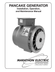
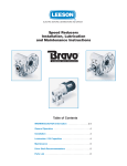
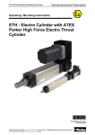
Installation, Operation and Maintenance Instructions for Industrial AC Induction Motors 140-6800 Frames (NEMA) 90 – 280 Frames (IEC) Regal Beloit AC Motors LEESON ELECTRIC Contact Motor Customer Service at: LEESON ELECTRIC: (262) 377-8810 Parts Dept (262) 377-8810 Warranty Service (800) 558-5490 LEESON CANADA: (905) 670-4770 www.Leeson.com LINCOLN MOTORS Contact Motor Customer Service at: LINCOLN MOTORS: (800) 668-6748 Parts Dept (216) 731-4790 Warranty Service (800) 254-4207 www.Lincolnmotors.com MARATHON ELECTRIC Contact Motor Customer Service at: MARATHON ELECTRIC (800) 284-6362 Parts Dept (800) 284-6362 Warranty Service (800) 254-4207 www.marathonelectric.com INSTALLER: PLEASE LEAVE THIS MANUAL FOR THE OWNER’S USE OWNER: READ AND SAVE THESE INSTRUCTIONS SAFETY INSTRUCTIONS This is the safety alert symbol. It is used to alert you to potential personal injury hazards. Obey all safety messages that follow this symbol to avoid possible injury or death. WARNING Before installing, using, or servicing this product, carefully read and fully understand the instructions including all warnings, cautions, & safety notice statements. To reduce risk of personal injury, death and/or property damage, follow all instructions for proper motor installation, operation and maintenance. These instructions are not intended as a complete listing of all details for installation, operation, and maintenance. If you have any questions concerning any of the procedures, STOP, and call the appropriate Regal-Beloit motor company. 3.3.6.2 Brake Motors 3.3.6.3 Space Heaters 1.0 INSTALLER / OWNER / OPERATOR RESPONSIBILITY 3.3.6.4 Thermal Protection General 1.1 Electrical Safety Thermostats, Thermisters & RTDs 1.2 Mechanical Safety 3.3.6.5 RTD Alarm & Trip Settings 1.3 Environmental Safety 3.3.7 Guards 2.0 RECEIVING & INSPECTION 3.4 Electrical Connections 2.1 Initial Inspection 3.4.1 Power Supply / Branch Circuit 2.1.1 Packing List & Inspect 3.4.1.1 Branch Circuit Supply 2.1.2 Turn Motor Shaft 3.4.1.2 Fuses, Breakers, Overload Relays 2.1.3 Check Nameplate 3.4.1.3 AC Power Supply Limits 2.2 Handling 3.4.2 Terminal Box 2.2.1 Correct Lifting Angles 3.4.2.1 Conduit opening 2.3 Storage 3.4.2.2 Hazardous Locations 2.3.1 Bearing Lubrication 3.4.3 Lead Connections 2.3.2 Shaft Rotation 3.4.3.1 Wire Size Requirements (Single Phase) 2.3.3 Damp or Humid Storage Locations 3.4.3.2 Extension Cords (Single Phase) 3.0 INSTALLATION AND OPERATION 3.4.4 Ground Connections 3.1 Location 3.4.5 Start Up 3.1.1 Selecting a Location 3.4.5.1 Start Up – No Load Procedure 3.1.2 Ambient Temperature Limits 3.4.5.2 Start Up – Load Connected Procedure 3.1.3 Construction Selection per Location 3.4.5.3 Jogging and/or repeated starts 3.1.3.1 Dripproof 4.0 MAINTENANCE 3.1.3.2 Totally Enclosed 4.1 General Inspection 3.1.3.3 Hazardous Locations Motors 4.1.1 Ventilation 3.2 Mounting Motor 4.1.2 Insulation 3.2.1 Rigid Base (Footed) 4.1.3 Electrical Connections 3.2.2 Rigid Base Hole Selection -6 or 8 Hole Bases 4.2 Lubrication and Bearings 3.2.3 Vertical 4.2.1 Grease Type 3.3 Application Assembly to Motor 4.2.2 Bearing Operating Temperature 3.3.1 General: Proper Alignment 4.2.3 Lubrication Interval 3.3.2 Direct Coupling 4.2.4 Lubrication Procedure 3.3.3 Direct Connected 4.2.5 Lubrication Example 3.3.4 Belted 4.3 Trouble Shooting 3.3.5 VFD Operation 4.3.1 General Trouble-Shooting Warnings 3.3.6 Accessories 3.3.6.1 General _________________________________________________________________________________________________________________________ Table of Contents motor immediately. Claims for any damage done in shipment must be made by the purchaser against the transportation company. 1.0 INSTALLER/OWNER/OPERATOR RESPONSIBILITY: 1.1 ELECTRICAL SAFETY WARNING: ELECTRICAL SHOCK HAZARD Electrical connections shall be made by a qualified electrician in accordance with all applicable codes, ordinances and sound practices. Failure to follow these instructions could result in serious personal injury, death and/or property damage. Only qualified personnel who are familiar with the applicable National Code (USA = NEC) and local codes should install or repair electrical motors and their accessories. WARNING: ELECTRICAL LIVE CIRCUIT HAZARD Do not touch electrically live parts. Disconnect, lockout and tag input power supply before installing or servicing motor (includes accessory devices). Use a voltmeter to verify that power is off before contacting conductors. WARNING: ELECTRICAL GROUNDING HAZARD Failure to properly ground motors, per the appropriate national code (such as the National Electrical Code NEC Article 430) and local codes may cause serious injury or death to personnel. For general information on grounding refer to NEC Article 250. (Also see “Ground Connections section 3.4.4“). WARNING: AUTOMATIC RESET PROTECTOR HAZARD Do not use automatic reset protectors if automatically restarting the motor will place personnel or equipment at risk. . Failure to follow this instruction could result in serious personal injury, death and/or property damage 2.1.2 TURN MOTOR SHAFT by hand to be certain that it rotates freely. Note: Shaft seals and bearing seals may add drag. 2.1.3 CHECK NAMEPLATE for conformance with purchase order requirements and compliance with power supply and control equipment requirements. 2.2 HANDLING: WARNING: FALLING OBJECT HAZARD Eyebolts or lifting lugs, where provided, are intended for lifting only the motor and accessories mounted by the motor manufacturer (unless specifically stated otherwise on the motor). Utilizing the motor lifting provision to lift other components such as pumps and gear boxes could result in serious personal injury, death and/or property damage. WARNING: FALLING OBJECT HAZARD Before using the lifting provision, check the eyebolts and/or other lifting means to assure they are not bent or damaged and are completely threaded, seated & secured to the motor. Equipment to lift motor must have adequate lifting capacity. While lifting the motor DO NOT stand under or in the vicinity of the motor. Failure to follow these instructions could result in serious personal injury, death and/or property damage. 2.2.1 LIFTING ANGLE LIMITATIONS WARNING: MANUAL RESET PROTECTOR HAZARD If a tripped manual reset thermal protector is exposed to a temperature less than –7°C (20°F) it may reset and restart the motor automatically. If an application requires a motor with a manual reset thermal protector that will be operated at temperatures less than –7°C (20°F) contact the manufacturer to review the application / motor requirements. Failure to follow this instruction could result in serious personal injury, death and/or property damage 1.2 MECHANICAL SAFETY WARNING: LOOSE PARTS HAZARD Before starting the motor, remove all unused shaft keys and loose rotating parts to prevent them from flying off. Failure to follow these instructions could result in serious personal injury, death and/or property damage. WARNING: ROTATING PARTS HAZARD Keep extremities, hair, jewelry and clothing away from moving parts. Failure to follow these instructions could result in serious personal injury, death and/or property damage. 1.3 ENVIRONMENTAL SAFETY WARNING: HAZARDOUS LOCATIONS (1) The NEC and the local authority having jurisdiction must be consulted concerning the installation and suitability of motors for use in Hazardous Locations. The local authority having jurisdiction must make the final determination of what type of motor is required. The application and operation is beyond the control of the motor manufacturer. (2) Division 1 Hazardous Locations motors can only be modified or reworked by the manufacturer or a facility that is Listed under UL’s category “Motors and Generators, Rebuilt for use in Hazardous Locations”. Failure to follow these instructions could result in serious personal injury, death and/or property damage. (3) Do not use a Hazardous Locations motor with a Variable Frequency Drive (VFD) unless the motor nameplate specifically states that the motor is suitable for use on Pulse Width Modulated (PWM) type VFD power. In addition, the nameplate must be marked with the inverter rating; for example, “2:1 CT”, “2 to 1 Constant Torque”, etc. 2.0 RECEIVING AND INSPECTION 2.1 INITIAL INSPECTIONS 2.1.1 CHECK PACKING LIST AND INSPECT the packaging to make certain no damage has occurred in shipment. If there is visible damage to the packaging, unpack and inspect the 2.3 STORAGE: Motors, not put into service immediately, must be stored indoors in a clean, dry location. Avoid locations with large temperature swings that will result in condensation. Motors must be covered to eliminate airborne dust and dirt. If the storage location exhibits high vibration, place isolation pads under motor to minimize damage to motor bearings. Bearings are grease packed at the factory; relubrication upon receipt of motor or while in storage is not necessary. If stored more than one year, add grease per lubrication instructions (Table 4-4) before start-up. 2.3.1 BEARING LUBRICATION: 2.3.2 SHAFT ROTATION: It is recommended that the motor shaft be rotated 5 to 10 rotations every three months to distribute the grease in the bearings. This will reduce the chance for corrosion to form on the bearing rolling elements and raceways. Note: Shaft seals and bearing seals may add drag. Treat unpainted flanges, shafts, and fittings with a rust inhibitor. Apply appropriate power to the motor’s space heaters (if so equipped) 2.3.3 DAMP OR HUMID STORAGE LOCATIONS: 3.0 INSTALLATION AND OPERATION WARNING: Only qualified personnel who are familiar with the appropriate national code, local codes and sound practices should install or repair electrical motors and their accessories. Installation should conform to the appropriate national code as well as local codes and sound practices. Failure to follow these instructions could result in serious personal injury, death and/or property damage. WARNING: ELECTRICAL LIVE CIRCUIT HAZARD Do not touch electrically live parts. Disconnect, Lockout and Tag input power supply before installing or servicing motor (includes accessory devices). Use a voltmeter to verify that power is off before contacting conductors. 3.1 LOCATION 3.1.1 SELECTING A LOCATION: Consideration should be given to environment and ventilation. Motors should be installed in an area that is protected from direct sunlight, corrosives, harmful gases or liquids, dust, metallic particles, and vibration. A motor with the proper enclosure for the expected operating condition should be selected. Provide accessible clearance for cleaning, repair, service, and inspections (See section 3.1.3 for construction clearances). The location should be considered for possible future motor removal / handling. The free flow of air around the motor should not be obstructed. 3.2 MOUNTING MOTOR: 3.2.1 RIGID BASE (FOOTED): The motor must be securely installed to a rigid foundation or a mounting surface to minimize vibration and maintain alignment between the motor shaft and the load’s shaft. The mounting surfaces of the four mounting pads must be flat within 0.01 inches for 210 frame & smaller; 0.015 inches for 250 frame & larger. [IEC 0.25 mm for 130 frame & smaller, 0.38 mm for 160 frame & larger]. This may be accomplished by shims under the motor feet. For special isolation mounting, contact manufacturer for assistance 3.2.2 RIGID BASE HOLE SELECTION -6 OR 8 HOLES 3.1.2 AMBIENT TEMPERATURE LIMITS: The ambient temperatures of the air inlet to the motor should not exceed 40°C (104°F) or be less than -30°C (-22°F) unless the motor nameplate specifically states an ambient temperature outside of these limits. The ambient inside an enclosure built around the motor shall not exceed the nameplate ambient. For ambient temperatures outside of these limits consult the motor manufacturer. CAUTION: INSULATION DEGRADATION WARNING Insulation at high temperatures ages at an accelerated rate. Each 10°C increase in temperature reduces the insulation life by one half. WARNING: HAZARDOUS LOCATIONS AMBIENT LIMIT: Division 1 Hazardous Locations motors shall NOT be operated below –25°C (-13°F) ambient. (Low temperatures reduce the component mechanical properties.) 3.1.3 CONSTRUCTION SELECTION per LOCATION: 3.1.3.1 DRIPPROOF (OPEN) MOTORS are intended for use indoors where the atmosphere is relatively clean, dry, and noncorrosive. Recommended a minimum clearance of ½ the shaft height between vent openings and the nearest obstruction. 3.1.3.2 TOTALLY ENCLOSED MOTORS are suitable for indoor or outdoor standard service applications. TEAO or AOM (Totally Enclosed Air Over) motors must be mounted in the air stream. When the motor nameplate states a minimum airflow the motor must be mounted in an air stream meeting this minimum value. TEFC (Totally Enclosed Fan Cooled) motors must meet a minimum distance of ½ the shaft height between the fan guard grill openings and the nearest obstruction. 3.1.3.3 HAZARDOUS LOCATIONS MOTORS: Hazardous Locations motors are intended for installations in accordance with NEC Article 500. For all installations involving Hazardous Locations motors, consult the applicable national codes, local codes, and the authority having jurisdiction. Division 1 Installations – includes Class I & II: Use only motors that are UL Listed and CSA Certified or UL Listed and UL Certified for Canada. These motors bear a separate nameplate that includes the UL Listing Mark and CSA Certification Mark or includes the UL Listing Mark and the UL Mark for Canada. This plate also bears the phrase: “ Electric motor for Hazardous Locations” and is marked with the Class, Group and Operating Temperature Code. Division 2 Installations – Class I only: Use only motors that are CSA Certified and bear the CSA Certification Mark. These motors include a phrase on the main motor nameplate that indicates the motor is CSA Certified for Class I, Division 2 / Zone 2 locations. Division 2 Installation – Class II only: Use only Class II motors as described above under “Division I Installations”. WARNING: EXPLOSION HAZARD A motor should never be placed in an area with a hazardous process or where flammable gases or combustible materials may be present unless it is specifically designed and nameplated for this type of service. Hazardous Locations motors are intended for installations in accordance with NEC Article 500. For all installations involving Hazardous Locations motors, consult the NEC, local codes, and the authority having jurisdiction. Failure to follow these instructions could result in serious personal injury, death and/or property damage. (For other limitations see section 1.3) 3.2.3 VERTICAL MOUNTING: ENCLOSURE PROTECTION CAUTION: Most Dripproof rigid base (footed) motors do NOT meet “Dripproof” requirements when mounted vertically. If the motor is located in unprotected environments, the addition of a drip cover may be available. Drip covers not available for cast iron rigid base motors. CAUTION: WARNING: FALLING OBJECT HAZARD The lifting provision on standard horizontal footed motors is not designed for lifting the motor in a vertical shaft up or shaft down position. (see 2.2.1 lifting angles). Lifting method / provisions for mounting a rigid base (footed) motor vertically is the responsibility of the installer. VERTICAL SHAFT DOWN: Most standard horizontal motors thru 449 Fr. (excluding brake motors) can be mounted in a vertical shaft down orientation. For vertical brake motors see section 3.3.6.2. VERTICAL SHAFT UP: WARNING: HAZARDOUS LOCATIONS VERTICAL MOUNT: Hazardous locations motors must NOT be mounted vertically shaft up without approval by the motor manufacturer. Without proper retaining provisions the rotor may move axially and contact components, creating a spark hazard. Belted or Radial Load when mounted vertically: For acceptable loads per frame size see Table 3-1 on motor manufacturer’s web site (listed on page 2). 3.3 APPLICATION ASSEMBLY TO MOTOR: CAUTION: EQUIPMENT DAMAGE: Do not connect or couple motor to load until correct rotational direction is established. 3.3.1 GENERAL: PROPER ALIGNMENT of the motor and driven equipment minimizes vibration levels, maximizes bearing life, and extends the overall life of the machinery. Consult the drive or equipment manufacturer for more information. CAUTION: BEARING FAILURE During assembly do NOT force components onto the shaft. Striking or hammering the component may result in bearing damage. 3.3.2 DIRECT COUPLING: Use flexible couplings if possible. For applications that apply radial, axial or moment loading on the motor shaft see section 3.3.3. must be measured with a belt tension gage. These inexpensive gages may be obtained through belt manufacturers, or distributors. CAUTION: BEARING FAILURE Unless approved by the motor manufacturer do NOT direct couple a vertical shaft up or roller bearing motor. Direct coupling a vertical shaft up motor or a motor with a roller bearing may result in bearing damage. Figure 2 3.3.3 DIRECT CONNECTED: Radial loading for direct connected equipment (gears, fans etc.) must be approved by the motor manufacturer unless within the maximum overhung load limits. For radial overhung load limits see Table 3-2 on motor manufacturer’s web site (listed on page 2). Combined loading (axial, radial and/or moments) must be approved by motor manufacturer. For belted loads see section 3.3.4. 3.3.4 BELTED: The goal of any belted system is to efficiently transmit the required torque while minimizing the loads on the bearings and shafts of the motor and driven equipment. This can be accomplished by following four basic guidelines: 1. Use the largest practical sheave diameter. 2. Use the fewest number of belts possible. 3. Keep sheaves as close as possible to support bearings. 4. Tension the belts to the lowest tension that will still transmit the required torque without slipping. It is normal for V-belts to squeal initially when line starting a motor Proper belt tension is determined by measuring the force required to deflect the center of the belt a given distance. The proper deflection (in inches) is determined by dividing the belt span in inches by 64. See figure 3. Calculate the proper deflection and then see Table 3-3 for the required “Deflected Force” to achieve that deflection. After tensioning the belt, rotate the sheaves for several rotations or operate the system for a few minutes to seat belts into the grooves, then re-tension the belts. New belts will stretch during use, and should be retensioned after the first eight hours of use. Figure 3 3.3.4.1 Sheave Diameter Guidelines: In general, smaller sheaves produce greater shaft stress and shaft deflection due to increased belt tension. See Table 3-3 for recommended minimum sheave diameters. Using larger sheaves increases the contact with belts which reduces the number of belts required. It also increases the belt speed, resulting in higher system efficiencies. See figure 1. When selecting sheaves, do not exceed the manufacturer's recommended maximum belt speed, typically 6,500 feet per minute for cast iron sheaves. Determine belt speed by the following formula: Figure 1 3.3.5 VFD (Variable Frequency Drives) OPERATION: Shaft RPM x 3.14 x Sheave Dia ( inches ) BELT SPEED (Ft/min) = 12 3.3.4.2 Number of Belts In general, use the fewest number of belts that will transmit the required torque without slipping. See Table 3-3 for recommended maximum number of belts. Each belt adds to the tension in the system, which increases load on the shafts and bearings. Belts are most efficient when operated at or near their rated horsepower. If the sheaves have more grooves than the number of belts required, use the grooves closest to the motor. 3.3.4.3 Sheave Location Install sheaves as close to the housing as possible to increase the bearing life of the motor and driven equipment (See figure 2) 3.3.4.4 Belt Tension CAUTION: Equipment Failure Caution Belt tensioning by feel is NOT acceptable. Tensioning by "feel" can be very misleading, and can damage motor and equipment. It is normal for V-belts to squeal initially when line starting a motor. In general, belt tensions should be kept as loose as possible while still transmitting the required torque without slipping. Belt tensions WARNING: VFD Motors with Reset Thermal Protectors UL Recognition, UL Listing, or CSA certification does not apply to motors that are equipped with a manual or automatic reset thermal protector when the motor is operated on VFD power. WARNING: Power Factor Correction Capacitors: Power factor correction capacitors should never be installed between the drive and the motor. CAUTION: VFD / Motor Setup: It is the responsibility of the startup personnel during set up of the VFD / motor system to properly tune the drive to the motor for the specific application per the VFD user manual. The correct voltage boost and volts per hertz settings are application dependent and unique to each motor design. Failure to connect over temperature devices (when provided) will void the warranty. Table 3-3 Recommended Minimum Sheave Diameters, Belt Type, Number of Belts and Deflected Force Motor Hp Min Sheave Dia (in) 1200 rpm Max # Belt of Belts Type 3VX 1 3VX 1 3VX 2 3VX 3 3VX 2 3VX 3 3VX 4 3VX 4 3VX 5 3VX 6 3VX 7 3VX 7 5VX 4 5VX 4 5VX 5 5VX 5 5VX 6 5V 7 5V 7 5V 8 8V 6 8V 7 8V 7 8V 8 8V 8 8V 9 Avg. Deflected Force (lbs) 34 4.0 3.1 2.8 3.3 4.0 4.7 5.4 5.4 6.0 5.6 5.9 11.6 14.6 14.1 14.5 16.0 14.1 15.4 16.0 27.6 27.1 30.3 29.1 31.6 30.7 Min Sheave Dia (in) 1800 rpm Max # Belt of Belts Type 3VX 1 3VX 1 3VX 3VX 2 3VX 3 3VX 3 3VX 4 3VX 4 3VX 4 3VX 6 3VX 7 3VX 7 3VX 7 3VX 8 5VX 4 5VX 4 5VX 6 5V 6 5V 7 5V 8 5V 9 5V/8V 11 / 7 5V/8V 12 / 7 5V/8V 13 / 8 5V/8V 14 / 9 5V/8V 15 / 9 8V 11 8V 12 8V 13 Avg. Deflected Force (lbs) Min Sheave Dia (in) 3600 rpm Max # Belt of Belts Type 3VX 1 3VX 1 3VX 1 3VX 3VX 2 3VX 3 3VX 2 3VX 3 3VX 3 3VX 3 3VX 4 Avg. Deflected Force (lbs) 0 75 22 22 22 1 2.4 2.2 3.1 2.2 1.5 2.4 2.4 2.2 2.5 2 2.4 2.4 2.9 2.4 3 3.0 2.4 2.9 2.4 2.3 5 3.0 3.0 3.7 2.4 2.5 7.5 3.8 3.0 4.1 3.0 4.2 10 4.4 3.8 4.3 3.0 3.8 15 4.4 4.4 5.4 3.8 4.4 20 5.2 4.4 4.8 4.4 5.0 25 6.0 4.4 5.2 4.4 4.7 30 6.8 5.2 5.3 40 6.8 6.0 6.0 50 8.2 6.8 5.9 60 8.2 7.4 13.3 75 10.0 8.6 14.3 100 10.0 8.6 13 125 12.0 10.5 13.1 150 13.2 10.5 13.4 200 15.0 13.2 13.1 250 15.0 14.0 13.8 300 16.0 14.0 23.4 350 16.5 14.5 26.0 400 17.5 15.0 25.7 450 18 16.0 25.2 500 18.5 16.5 26.9 600 17.5 26.3 700 19.0 27.3 800 20.0 28.2 Notes: 1. Horsepower is the nameplate motor horsepower, and RPM is the motor (driver) speed. 2. Minimum sheave diameters are from NEMA standards where applicable. 3. For variable speed applications or values outside these recommendations, consult motor manufacturer. 4. Selections are based on a 1.4 service factor, 5 to 1 speed ratio and various Power Transmission Manufacturers’ catalogs. 5. These selections are for Narrow V-belt sections only. Consult manufacturer for details on conventional V-belt sections (A, B, C, D and E), or other belt types. 6. “Average Deflected Force is per section 3.3.4.4 of this document and is the force required to deflect the center of a belt 1/64 of the belt span distance. Tolerance on this force is ±1 lbf for forces ≤10 lbs, and ±2 lbs for forces >10 lbs as measured utilizing a belt tension gage. 7. When more than one belt is required the belts must be a matched set (matched for length). 8. If possible, the lower side of the belt should be the driving side to increase the length of wrap on the sheave). 9. For belted loads do not exceed 125% of 60 Hz operating RPM. _________________________________________________________________________________________________________________________ 3.3.5.1 Overspeed Capability: Belted loads: Do not exceed 125% of 60 Hz operating RPM. Table 3-4 Maximum Safe Continuous Speed (RPM) For Coupled and Direct Connected Loads NEMA / [IEC] Frame Size 56-180 [80-110] 2-Pole 4, 6, or 8 Pole to Table 3-5 values. Definite purpose VFD motors may accommodate longer cable lengths. For additional information contact motor manufacturer. Table 3-5 Max Cable Lengths General Purpose Motors These values are based on 3 kHz carrier frequency. Add suitable VFD output-side filters when exceeding the listed values. 7200 * 5400 * Frame Size 230V 460 V 575 V 210-250 [130-160] 5400 * 4200* NEMA 56-320 600 ft. 125 ft. 40 ft. 280 [180] 5400 * 3600 NEMA 360-5011 1000 ft. 225 ft. 60 ft. 320 [200] 4500 * 3600 IEC 80-200 180 m. 40 m. 12 m. 360 [225] 4500 * 2700 3600 2700 IEC 225-280. 300 m. 70 m. 18 m. 400-440 [250-280] >440 [>280] 3600 1800 * = Fan cooled motors (Totally Enclosed & Hazardous Locations Motors) are limited to a maximum safe continuous speed of 4000 RPM For higher speeds or shortened duty cycle contact motor manufacturer 3.3.5.2 Cable Lengths: For optimum insulation life, limit VFD to motor cable lengths of general purpose motors 3.3.5.3 VFD Grounding: Equipment grounding conductors may be run in the same conduit as the AC motor power leads. This wire must be used as the equipment ground for the motor and not as the fourth current carrying wire of a “WYE” motor circuit. The grounded metal conduit carrying the output power conductors can provide EMI shielding, but the conduit does not provide an adequate ground for the motor; a separate grounding conductor must be used. Grounding the motor neutral (WYE) of a VFD powered motor may result in a VFD ground fault trip. Improper grounding of an inverter fed motor may result in frame voltages in excess of 500 Volts. See Grounding section 3.4.4 Resistance Temperature Detectors (RTD): When winding and/or bearing RTDs are provided the RTD lead markings are defined on the nameplate. (Normally “R1”, “R2”, “R3” etc.) 3.3.5.4 VFD – Single Phase: CAUTION: SINGLE PHASE MOTOR FAILURE: 3.3.6.5 RTD Alarm & Trip Settings: Single Phase motors are NOT suitable for use on VFD power. Connecting a Single Phase Motor to a VFD voids the warrantee. Tables 3-6 & 3-7 are suggested initial RTD alarm and trip settings. For motors found to operate significantly below these values the settings may be reduced accordingly. 3.3.6 ACCESSORIES / PROVISIONS: 3.3.6.1 General: Carefully read and understand the accessory Table 3-6 Winding RTD – Temperature Limit ( C) 40 C Max Ambient manufacturer’s instructions, supplied with motor. Contact the accessory manufacturer for additional information. Motor Load 3.3.6.2 Brake Motors: CAUTION: Vertical Motor Premature Brake Failure Motors with brakes that are designed for vertical applications are equipped with springs to support the brake pressure plate. Mounting a horizontal brake motor vertically shaft up or down may require a pressure plate spring modification. Failure to modify the brake for the vertical application may result in premature brake failure. If in question, consult brake literature or brake manufacturer. The space heater temperature rating when used in Class I, Division 2 motors shall NOT exceed 80% of the auto ignition temperature of the hazardous gas or vapor. See the space heater nameplate on motor for heater Temperature Code and heater rating. Failure to follow this instruction could result in serious personal injury, death and/or property damage Alarm Trip Alarm Trip Up to 1.0 SF 130 140 155 165 >1.0 to 1.15 SF 140 150 160 165 Up to 40 C C > 40 Bearings that are Heat Stabilized to 150 C 3.3.6.3 Space Heaters: WARNING: DIVISION 2 EXPLOSION HAZARD Class F Temp Rise≤ 105 C Table 3-7 Bearing RTD – Temperature Limit ( C) 40 C Max Ambient Alarm Trip Ambient Brake Solenoid Wiring: Do NOT connect the brake solenoid to the output of a VFD. The brake solenoids must be wired to 50/60 Hz line power Motors provided with space heaters have two leads that are brought into the conduit box or into an auxiliary box. These leads are marked ”H1”, “H2” (”H3”, “H4” if a second space heater is supplied). See the space heater nameplate on motor for heater rating. Class B Temp Rise≤ 80 C 95 100 110 115 130 135 3.3.7 GUARDS: WARNING: ROTATING PARTS HAZARD When devices are assembled to the motor shaft, be sure to install protective devices such as belt guards, chain guards, and shaft covers. These devices must protect against accidental contact with extremities, hair, and clothing. Consider the application and provide guarding to protect personnel. Remove all unused shaft keys and loose rotating parts to prevent them from flying off and causing bodily injury. Failure to follow this warning could result in serious personal injury, death and/or property damage. 3.3.6.4 Thermal Protection: 3.4 General Information: When thermal protection is provided, one of the following will be stamped on the nameplate: 1. “THERMALLY PROTECTED” This motor has built in thermal protection. Thermal protectors open the motor circuit electrically when the motor overheats or is overloaded. The protector cannot be reset until the motor cools. If the protector is automatic, it will reset itself. If the protector is manual, disconnect motor from power supply. After protector cools (five minutes or more) press the reset button and reapply power to the motor. In some cases a motor is marked “Auto” and the connection diagram on the motor will identify T’Stat leads – see “2 ” below. (See warnings on Manual and Automatic reset protectors - section 1.1) WARNING: ELECTRICAL HAZARDS Before proceeding read Section 1-1 on Electrical Safety. Failure to follow the instructions in Section 1-1 could result in serious personal injury, death and/or property damage 2. “WITH OVERHEAT PROTECTIVE DEVICE”: This motor is provided with an overheat protective device that does not directly open the motor circuit. Motors nameplated with this phrase have either thermostats, thermisters or RTD’s. The leads to these devices are routed into the motor conduit box or into an auxiliary box. The lead markings are defined on the nameplate (normally “P1”, “P2”) . The circuit controlled by the overheat protection device must be limited to a maximum of 600 volts and 360 volt-amps. See connection decal provided inside the terminal box cover. Failure to connect these over temperature devices (when provided) will void the warranty. WARNING: EXPLOSION HAZARD For Hazardous Locations motors provided with thermostats UL and the NEC require connection of thermostat leads into the control portion of a manual reset start circuit. Failure to follow this instruction could result in serious personal injury, death and/or property damage ELECTRICAL CONNECTIONS: 3.4.1 POWER SUPPLY / BRANCH CIRCUIT WARNING: POWER SUPPLY INCOMPATIBILITY HAZARD Check power supply to make certain that voltage, frequency and current carrying capacity are in accordance with the motor nameplate. Failure to match motor nameplate values could result in serious personal injury, death and/or property damage WARNING: BRANCH CIRCUIT SUPPLY HAZARD Motor and control wiring, fusing, overload protection, disconnects, accessories and grounding must always conform to the applicable electrical codes as well as local codes and sound practices. 3.4.1.1 Branch Circuit Supply to a motor should include a disconnect switch, short circuit current fuse or breaker protection, motor starter (controller) and correctly sized thermal elements or overload relay protection. 3.4.1.2 Fuses, Breakers, Overload Relays Short Circuit Current Fuses or Breakers are for the protection of the branch circuit. Starter or motor controller overload relays are for the protection of the motor. Each of these should be properly sized and installed per the applicable electrical codes as well as local codes and practices. WARNING: PROTECTIVE DEVICE DISABLED HAZARD DO NOT bypass or disable protective devices. Protection removal could result in serious personal injury, death and/or property damage 3.4.1.3 AC Power Supply Limits Motors are designed to operate within the following limits at the motor terminals: 1- AC power is within +/- 10 % of rated voltage with rated frequency applied. (Verify with nameplate ratings) OR 2- AC power is within +/- 5% of rated frequency with rated voltage OR 3- A combined variation in voltage and frequency of +/- 10% (sum of absolute values) of rated values, provided the frequency variation does not exceed +/-5% of rated frequency. 4- For 3 phase motors the line to line full load voltage must be balanced within 1%. 5If the motor is rated 208-230V, the voltage deviations must be calculated from 230V. CAUTION: Reduced Motor Performance Operation outside of these limits will degrade motor performance and increase operating temperature. 1 1/2 2 3 5 #4 #10 #8 #8 #6 #0 #8 #6 #6 #4 #6 #4 #4 #2 #4 #2 #2 #0 3.4.4 GROUND CONNECTION(S): WARNING: ELECTRICAL GROUNDING HAZARD For general information on grounding (USA) refer to NEC Article 250. Improper grounding of an inverter fed motor may result in frame voltages in excess of 500 Volts. In making the ground connection, the installer must make certain that a good electrical connection is obtained between motor and grounding lead. Failure to properly ground motors, per the applicable national code (such as NEC Article 430) and local codes may cause serious injury or death to personnel. motors are typically provided with large terminal boxes. Most motors have conduit access in 90 degree increments, the terminal box conduit opening is typically provided via knockouts, holes with covers, or the terminal box is rotate-able. Fabricated conduit boxes may have a removable plate for the installer to provide correctly sized hole(s). Primary “Internal” Ground: A grounding conductor must be connected to the grounding terminal provided in the terminal housing. This grounding terminal is either a ground screw, ground lug, or a tapped hole to be used with a separately provided ground screw. The internal grounding feature is accessible inside the terminal housing and must be used as the primary grounding connection. Secondary “External” Ground: Some motors are provided with a supplemental grounding terminal located on the external surface of the motor frame or feet. This external terminal is for supplemental bonding connections where local codes permit or require such connection 3.4.2.2 Hazardous Locations Motors: 3.4.5 START UP: 3.4.2 TERMINAL BOX: 3.4.2.1 Conduit Opening: For ease of connections, WARNING: EXPLOSION HAZARDS (1) Terminal Boxes mounted to motor with a pipe nipple: If a pipe nipple mounted terminal box is removed or rotated it must be reassembled with a minimum of five full threads of engagement. (2) Component Removal: Do not set a terminal box component on its machined surfaces. Prior to component reassembly wipe clean all machined surfaces. (3) Machined Surface Gap (Hazardous Locations Terminal Boxes): The gap between mating surfaces with the machined terminal box MUST BE LESS THAN 0.002 inches. This gap must be checked with a feeler gage along the entire perimeter. If there is visible damage to the mating surfaces, or if the gap between these surfaces exceeds 0.002 inches, DO NOT complete the installation and contact the motor manufacturer. Failure to follow these instructions could result in serious personal injury, death and/or property damage 3.4.3 LEAD CONNECTIONS Electrical connections to be made per nameplate connection diagram or separate connection plate. In making connections follow the applicable electrical code as well as local codes and practices. WARNING: ELECTRICAL CONNECTION HAZARD Failure to correctly connect the motor leads and grounding conductor can result in injury or death. Motor lead connections can short and cause damage or injury if not well secured and insulated. 3.4.3.1 Wire Size (Single Phase) Requirements The minimum wire size for Single Phase, 115 & 230 Volt Circuits must meet table 3-8 for a given distance between motor and either Fuse or Meter Box. 3.4.3.2 Extension Cords (Single Phase Motors): Where an extension cord(s) is utilized to provide power to the motor the extension cord(s) must be…(1) the proper gauge size per table 3-8, (2) in good working condition (3) properly grounded. Table 3-8 Minimum Wire Size Single Phase 115 & 230 Volt Circuits Distance (Feet) - Motor to Fuse or Meter Box Motor HP 1/4 1/3 1/2 3/4 1 100 Ft. 200 Ft. 300 Ft. 500 Ft. 115 230 115 230 115 230 115 230 #14 #12 #10 #10 #8 #14 #14 #12 #12 #10 #10 #10 #8 #6 #6 #12 #12 #10 #10 #8 #8 #6 #6 #4 #4 #10 #10 #8 #8 #6 #6 #4 #4 #2 #8 #8 #6 #6 #4 WARNING: ELECTRICAL SHOCK HAZARD: Be certain that all connections are secure and the conduit box cover is fastened in place before electrical power is connected. Failure to follow these instructions could result in serious personal injury, death, and/or property damage. WARNING: LOOSE & ROTATING PARTS HAZARD Before proceeding read Section 1-2 on Mechanical Safety. Failure to follow the instructions in Section 1-2 could result in serious personal injury, death and/or property damage WARNING: EXCESSIVE SURFACE TEMPERATURE HAZARD Motors with the temperature code stated on the nameplate are designed to operate within this limit. Improper application or operation can cause the maximum surface temperature to be exceeded. A motor operated in a Hazardous Location that exceeds this surface temperature limit increases the potential of igniting hazardous materials. For conditions that increase surface temperature see motor manufacturer’s web sit. Failure to follow these instructions could result in serious personal injury, death and/or property damage. CAUTION: HOT SURFACE Normal motor surface temperatures may exceed 90 ° C (194° F). Touching the motor frame may cause discomfort or injury. Surface temperatures should only be measured with suitable instruments and not estimated by hand touch. 3.4.5.1 Start Up - No Load Procedure 1. Check Instructions: Before startup carefully read and fully understand these instructions including all warnings, cautions, and safety notice statements. 2. Motor out of storage after more than three months: Check winding insulation integrity with a Megger. If winding resistance to ground is less than 1.5 Meg-ohms consult the local authorized service shop before energizing the motor. 3. Check Installation: Mechanical - Check tightness of all bolts and nuts. Manually rotate the motor shaft to ensure motor shaft rotates freely. Note: Shaft & bearing seals will add drag. Electrical - Inspect all electrical connections for proper terminations, clearance, mechanical tightness and electrical continuity. Be sure to verify connections are made per the nameplate connection diagram or separate connection plate. Replace all panels and covers that were removed during installation before energizing the motor. 4. Energize Motor: Check Rotation If practical check motor rotation before coupling to the load. Unlock the electrical system. Momentarily provide power to motor to verify direction of rotation. If opposite rotation is required, lock out power before reconnecting motor. If motor has a rotational arrow only operate the motor in the rotation identified. Reapply power to ensure proper operation. 5. Record No Load Amps, Watts & Voltage: Recommend - To establish a baseline value check and record the no load amps, watts, and voltage. 3.4.5.2 Start Up – Load Connected Procedure 1. Check Instructions: Before startup carefully read and fully understand these instructions including all warnings, cautions, & safety notice statements. 2. Coupling Installation: Check that the connected equipment is properly aligned and not binding. Check that all guards and protective devices are properly installed. 3. Energize Motor: When all personnel are clear of the machine, apply power and verify that the load is not transmitting excessive vibration back to the motor though the shaft or the foundation. Verify that motor amps are within nameplate rating. For repeated starts see 3.4.5.3. The equipment can now be fully loaded and operated within specified limits as stated on the nameplate. 3.4.5.3 Jogging and/or Repeated Starts Do not start more than twice in succession under full load. Repeated starts and/or jogs of induction motors can cause overheating and immediate failure. Contact the motor manufacturer if it is necessary to repeatedly start or jog the motor. 4.0 MAINTENANCE: Check that the ventilation openings and/or exterior of the motor is free of dirt, oil, grease, water, etc, which can accumulate and block motor ventilation. If the motor is not properly ventilated, overheating can occur and cause early motor failure. 4.1.1 VENTILATION: 4.1.2 INSULATION: Use a “Megger” periodically to ensure that the integrity of the winding insulation has been maintained. Record the Megger readings. If winding resistance to ground is less than 1.5 Meg-ohms consult the local authorized service shop before reenergizing the motor. 4.1.3 ELECTRICAL CONNECTIONS: Check all electrical connectors to be sure that they are tight. 4.2 LUBRICATION & BEARINGS: The lubricating ability of grease (over time) depends primarily on the type of grease, the size of the bearing, the speed at which the bearing operates and the severity of the operating conditions. Longer bearing life can be obtained if the listed recommendations are followed: NOTE: If lubrication instructions are provided on the motor nameplate, the nameplate instructions will supersede these instructions. Motors marked “Permanently Lubricated” do not require additional service”. CAUTION: BEARING / MOTOR DAMAGE WARNING Lubricant should be added at a steady moderate pressure. If added under heavy pressure bearing shield(s) may collapse. Over greasing bearings greatly increases bearing friction and can cause premature bearing and/or motor failure. WARNING: Hazardous Locations Motor Repair HAZARD: Division 1 Hazardous Locations motors can only be modified or repaired by the manufacturer or a facility that is Listed under UL’s category “Motors and Generators, Rebuilt for use in Hazardous Locations”. Failure to follow these instructions could result in serious personal injury, death and/or property damage. 4.2.1 GREASE TYPE (unless nameplate states otherwise): WARNING: ELECTRICAL SHOCK HAZARD Electrical connections are to be made by a qualified electrician in accordance with all applicable codes, ordinances and sound practices. Failure to follow these instructions could result in serious personal injury, death and/or property damage. Only qualified personnel who are familiar with the applicable national codes, local codes and sound practices should install or repair electric motors and their accessories. Nameplate Ambient Temperature below -30°C (-22°F): Special low temperature grease is recommended, such as Aeroshell 7 or Beacon 325 for ball bearings and Mobil SHC 100 for roller bearings. WARNING: ELECTRICAL LIVE CIRCUIT HAZARD Do not touch electrically live parts. Disconnect, lockout and tag input power supply before installing or servicing motor (includes accessory devices). 4.1 GENERAL INSPECTION Inspect the motor approximately every 500 hours of operation or every three months, whichever occurs first. Keep the motor clean and the ventilation and fin openings clear. The following steps should be performed at each inspection: Nameplate Ambient Temperature between -30°C (-22°F) to 65°C (150°F) inclusive: Recommended grease for standard service conditions is Polyrex EM (Exxon Mobil). Equivalent and compatible greases include: Texaco Polystar RB, Rykon Premium #2, Pennzoil Pen 2 Lube, Chevron SRI & Mobil SHC 100. Nameplate Ambient Temperature above 65°C (150°F): Dow Corning DC44 or equivalent, a special high temperature grease is required. Note that Dow Corning DC44 grease does not mix with other grease types. 4.2.2 BEARING OPERATING TEMPERATURE: CAUTION: HOT SURFACE The external surface temperature of the end shield (bracket) bearing hub may reach 100° C (212° F) during normal operation. Touching this surface may cause discomfort or injury. Surface temperatures should only be measured with suitable instruments and not estimated by hand touch. For RTD settings see Table 3-7. _________________________________________________________________________________________________________________________ 4.2.3 LUBRICATION INTERVALS: (For motors with regreasing provisions) Eq. 4.2 Lubrication Interval = [(Table 4-1) hrs] x [Interval Multiplier (Table 4-2)] x [Construction Multiplier (Table 4-3)] Recommended lubrication intervals are shown in Table 4-1. These values are based on average use. NEMA / [IEC] Frame Size 56-180 [80-110] Table 4-1 Lubrication Intervals Operating Speed – RPM (See Table 3.4 for Maximum Operating Speed) <7200 <5400 <4500 <3600 <1800 <1200 4000 Hrs 5000 Hrs 6000 Hrs. 17000 Hrs. 20000 Hrs. 210-250 [130-160] 2500 Hrs 4000 Hrs 5000 Hrs. 12000 Hrs. 16000 Hrs. 280 [180] 2000 Hrs 3000 Hrs 4000 Hrs. 10000 Hrs. 14000 Hrs. 320 [200] 2000 Hrs 3000 Hrs. 9000 Hrs. 12000 Hrs. 360 [225] 1500 Hrs 2000 Hrs. 8000 Hrs. 10000 Hrs. 1500 Hrs. 1000 Hrs. 4000 Hrs. 3000 Hrs. 7000 Hrs. 5000 Hrs. 400-440 [250 – 280] >440 [>280] 2500 Hrs. Seasonal Service: If motor remains idle for more than six months, Lubricate at the beginning of the season, then follow lubrication interval. Do not exceed maximum safe operating speed Table 3-4 without manufacturer’s approval Table 4-2 Service Conditions Use highest level Multiplier: Maximum Ambient Temperature and Contamination are independent factors Severity of Service Maximum Ambient Temperature Atmospheric Contamination Multiplier Standard Less than 40° C (104° F) Clean, Slight Corrosion, indoors, less than 16 hrs per day Severe Above 40° C (104° F) to 50° C Moderate dirt or Corrosion or outdoors or more than 16 hrs per day 0.5 Extreme Greater than 50° C or Class H Insulation Severe dirt or Abrasive dust or Corrosion 0.2 1.0 ________________________________________________________________________________________________________________________ Table 4-3 Construction Multiplier Construction Multiplier Angular Contact or Roller Bearing 0.5 Vertical Motor 0.5 All others 1.0 IEC Cu. In. Fluid oz Re-install grease inlet and drain plugs (if removed). WARNING: EXPLOSION HAZARD Do NOT energize a Hazardous Locations motor without all grease fittings properly installed. 4.2.5 EXAMPLE: LUBRICATION Table 4-4 Relubrication Amounts Frame Size Volume NEMA 4. ml 140 90 0.25 0.14 4.0 180 110 0.50 0.28 8.0 210 130 0.75 0.42 12.5 250 160 1.00 0.55 16.0 280 180 1.50 0.83 25.0 320 200 2.00 1.11 33.0 360 225 3.00 1.66 50.0 400 250 3.80 2.11 62.0 440 280 4.10 2.27 67.0 >440 >280 4.50 2.50 74.0 For regreasing while operating multiply volume by 125% 4.2.4 LUBRICATION PROCEDURE: (For Motors with Regreasing Provisions) Added grease must be compatible with the original equipment’s grease. If a grease other than those stated in 4.2.1 is to be utilized contact the motor manufacturer. Nameplate information supersedes section 4.2.1 (GREASE TYPE). New grease must be free of dirt. Failure to follow these instructions and procedure below may result in bearing and/or motor damage. For an extremely dirty environment, contact the motor manufacturer for additional information. LUBRICATION PROCEDURE: 1. Clean the grease inlet plug or zerk fittings prior to regreasing. 2. (If present) Remove grease drain plug and clear outlet hole blockage. CAUTION: GREASE DRAIN PLUGGED: Old grease may completely block the drain opening and must be mechanically removed prior to regreasing. Forcing a blocked drain open by increased greasing pressure may collapse bearing shields and / or force excess grease through the bearings and into the motor. 3. Add grease per Table 4-4 Assume - NEMA 286T (IEC 180), 1750 RPM Vertical motor driving an exhaust fan in an ambient temperature of 43° C and the atmosphere is moderately corrosive. 1. Table 4-1 list 10,000 hours for standard conditions. 2. Table 4-2 classifies severity of service as “Severe” with a multiplier of 0.5. 3. Table 4-3 lists a multiplier value of 0.5 for “Vertical” 4. (Eq. 4.2) Interval = 10,000 hrs x 0.5 x 0.5 = 2500 hrs 3 Table 4-4 shows that 1.5 in of grease is to be added. 3 Relubricate every 2,500 hrs of service with 1.5 in of recommended grease. 4.3 TROUBLE-SHOOTING WARNING: READ INSTRUCTIONS: Before trouble-shooting a motor, carefully read and fully understand the warnings, cautions, & safety notice statements in this manual. WARNING: Hazardous Locations Motor Repair: Motors nameplated for use in Division 1 Hazardous Locations can only be disassembled, modified or repaired by the plant of manufacturer or a facility that is Listed under UL’s category “Motors and Generators, Rebuilt for use in Hazardous Locations”. Failure to follow these instructions could result in serious personal injury, death and/or property damage CAUTION: DISASSEMBLY APPROVAL REQUIRED: Motor disassembly must be performed by a party approved by the motor manufacturer. To disassemble the motor without approval voids the warranty. 4.3.1 GENERAL TROUBLE-SHOOTING WARNINGS 1. 2. 3. 4. 5. DISCONNECT POWER TO THE MOTOR BEFORE PERFORMING SERVICE OR MAINTENANCE. Discharge all capacitors before servicing motor. Always keep hands and clothing away from moving parts. Be sure required safety guards are in place before starting equipment. If the problem persists contact the manufacturer. Table 4-5 Motor Trouble-shooting Chart Issue: Likely Cause: Corrective Action: Motor fails to start upon initial installation: B.) Supply voltage is too low or is severely unbalanced (one (1) Check power supply fuses (2) Match motor lead wiring to nameplate connection diagram and supply voltage (3) Ensure that steady state supply voltage at motor phase is low or missing). terminals is within limits (see section 3.4.1.3). Correct as needed (4) Obtain correct Motor leads are miswired at conduit box. motor to match actual supply voltage. C.) Driven load exceeds motor capacity D.) Load is jammed. (1) Verify that motor & load turn freely (2) Disconnect motor from load & ensure motor turns freely. Note: Roller bearings make noise when motor is uncoupled and shaft is rotated (3) Verify that motor starts when disconnected from load (4) Remove excessive / binding load if present. E.) VFD with power factor capacitors installed Remove power factor correction capacitors if equipped F.) VFD with motor neutral lead grounded Ensure that motor neutral lead is ungrounded G.) VFD programmed incorrectly (1) Repeat checks listed above (2) Verify that VFD current limit and starting boost are set correctly (5) Double-check motor and feedback parameter settings and VFD permissives (6) Repeat autotune (for vector drives) procedure (7) Consult VFD supplier. A.) Motor has been running, then slow down, stalls, or fails to restart: (1) Replace fuse or reset circuit breaker. Allow motor to cool down before resetting manual protector on motor. Warnings - See section 1.1 for automatic and manual reset protector warnings (2) Verify that rated and balanced supply voltage has been restored before restarting motor. Measure voltage during restart. Ensure that steady state supply voltage at motor terminals is within limits (see section 3.4.1.3). A.) Supply voltage has drooped or has become severely unbalanced B.) Motor is overloaded C.) Motor bearings are seized D.) Load Is jammed. E.) VFD will not restart motor after tripping (1) Check fault codes on VFD and follow VFD troubleshooting procedures (2) Verify that VFD input voltage is balanced and within limits (3) Remove excessive mechanical load if present. F.) Capacitor failure on single phase motor (if equipped) Warning: Potential Shock Hazard: Contact service shop to check capacitor. (1) Verify that motor & load turn freely. Repair binding components as needed (2) Reduce driven load to match motor capacity or increase motor size to match load requirements. Motor takes too long to accelerate: A.) Motor leads are not connected correctly Match motor lead wiring to nameplate diagram. B.) Supply voltage has drooped or become severely unbalanced. C.) Load exceeds motor capability D.) Faulty start capacitor (Single Phase) Motor may be too small for load. Record acceleration time. Start capacitors may fail if acceleration time exceeds 3 seconds. E.) Mechanical Failure (1) Check to make sure motor & load turn freely (2) Disconnect motor from load & ensure motor turns freely (1) Ensure that steady state supply voltage at motor terminals is within limits (see section 3.4.1.3). Correct as needed (2) Obtain correct motor to match actual supply voltage. Determine correct motor size and contact motor representative to obtain replacement motor. Motor rotates in the wrong direction: A.) Incorrect wiring connection at motor [Single Phase] Reconnect motor according to wiring schematic provided. Some motors are non-reversible Note: [Three Phase] Interchange any two power supply (phase) leads. Motor overheats or overload protector repeatedly trips A.) Driven Load is excessive (1) If motor current exceeds nameplate value, ensure that driven load has not increased. Correct as needed. (2) If new motor is a replacement, verify that the rating is the same as the old motor. If previous motor was a special design, a general purpose motor may not have the correct performance. B.) Ambient temperature too high Most motors are designed to operate in an ambient up to 40 C. (See section 4.2.2 Hot Surface Caution) C.) Motor cooling fins and/or vent openings blocked Remove foreign materials – clear vent openings, fan guard air inlets and frame fins (TEFC motors) D.) Insufficient Air Flow TEAO (Totally Enclosed Air Over) motors: Measure airflow next to motor surface and obtain minimum requirements from motor manufacturer. E.) Motor is started too frequently See section 3.4.5.3 F.) Supply voltage too low, too high, or unbalanced (1) Ensure that steady state supply voltage at motor terminals is within limits (see section 3.4.1.3) Correct as needed (2) Reconnect motor per input voltage (3) Obtain correct motor to match power supply. Motor Vibrates Motor misaligned to load. Realign load B.) Load out of balance (Direct drive application) (1) Ensure that load is dynamically balanced: (2) Remove motor from load and inspect motor by itself. Verify that motor shaft is not bent. Rule of thumb is 0.002” runout for shafts extension lengths up to 3.00”. Add 0.0005” per every additional inch of shaft length beyond 3.00”. C.) Uneven tension on multiple belts Mixing new with used belts. Replace multiple belt applications with a complete set of matched belts. D.) Driven load operating at resonant point / natural frequency. (1) De-energize motor and record vibration as load coasts from 100% speed to 0 RPM. If vibration drops immediately, vibration source is electrical. If levels do not drop immediately, source is mechanical (2) Redesign system to operate below the resonant point (3) On VFD-driven loads, program skip frequencies to bypass resonant points (4) Increase carrier frequency to obtain <3% THD current (5) On variable torque loads reduce volts/hertz below base speed. E.) VFD torque pulsations (1) Adjust VFD to obtain <3% THD current @ rated motor current (2) Adjust VFD stability for smooth operation. Vector drives may be unstable at light load. F.) Motor miswired at terminal box Match motor lead wiring to nameplate connection diagram. G.) Uneven, weak or loose mounting support. Shim, strengthen or tighten where required. H.) Motor bearings defective Test motor by itself. If bearings are bad, you will hear noise or feel roughness. Roller bearings are normally noisy when operated without load. If sleeve bearing, add oil per nameplate instructions. For motors with regreasing provisions, add grease per relubricating instructions (see section 4.2.3). If noise persists contact warranty service. I.) Motor out of balance Disconnect from load. Set motor on rubber pads on solid floor. Secure a ½ height key in shaft keyway and energize from balanced power supply @ rated voltage. Record vibration levels and compare with appropriate standards. If excessive vibration persists contact motor manufacturer. A.) Bearings repeatedly fail. A.) Load to motor may be excessive or unbalanced (1) If belt drive check system per section 3.3.4. (2) Other than belting, check loading on motor shaft. An unbalanced load will also cause the bearings to fail. (3) Check runouts of mating components, such as a C-face and pump flange. B.) Bearings contaminated. Motor enclosure not suitable for environment. Replace with correct enclosure construction C.) Incorrect grease or bearings for ambient extremes. See section 4.2.1 D.) VFD bearing damage Ground brush, common mode filter, or insulated bearings must be added. Contact motor manufacturer. Motor, at start up, makes a loud rubbing, grinding, or squealing noise. A.) Contact between rotating and stationary components Belt squeal during across the line starting is normal: (1) Verify that supply voltage is within limits (see section 3.4.1.3). (2) Ensure that motor lead wiring matches nameplate connection diagram: (3) Isolate motor from load. (4) To locate point of contact turn motor shaft by hand. (5) If point of contact is not located contact motor service shop. Start capacitors repeatedly fail. A.) The motor acceleration time is too long Motor may be too small for load. Record acceleration time. Start capacitors may fail if acceleration time exceeds 3 seconds. B.) Motor is being started too frequently Excessive starting will damage motor capacitors. Contact motor manufacturer if motor is started more than 20 times/hour or if acceleration time exceeds 3 seconds. C.) Motor voltage low Verify that voltage at the motor terminals is within limits (see section 3.4.1.3). D.) Defective start switch inside motor Motor internal switch failure overheats start capacitor. Contact service shop or motor manufacturer. Run capacitor fails. A.) High ambient temperature Verify that the ambient does not exceed motor’s nameplate value B.) Input voltage exceeds limit Verify that voltage to the motor terminals is within limits (see section 3.4.1.3). C.) Power surge to motor (caused by lightning strike or other If a common problem, install surge protector. high transient voltage).