1
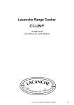
« CLASSIC »
S 2150 A, AMM, AMT
Watermixing- and measurement appliance
USER’S MANUAL
Contents
IMPORTANT SAFEGUARDS………………………………………………………………. 3
1 GENERAL DESCRIPTION………………………………………………………………. 4
2 UNPACKING OF THE UNIT ……………………………………………………………. 5
3 INSTALLING THE UNIT ………………………………………………………………... 5
3.1 Fitting ………………………………………………………………………………… 5
3.2 Hints for wall mounting the S 2150 ………………………………………………….. 6
4 OPERATING THE S 2150 ………………………………………………………………… 6
4.1 Switching on the S 2150 ……………………………………………………………… 6
4.2 Adjusting the batch quantity ………………………………………………………… 6
4.3 Setting the batch temperature ………………………………………………………… 6
4.4 Starting the batch ……………………………………………………………………....7
4.5 Interrupting the batch …………………………………………………………………. 7
4.6 Cancelling the batch ………………………………………………………………….. 7
4.7 Switching off the S 2150 ……………………………………………………………... 7
4.8 Calibration of the batch according to the pressure conditions of water inlet
7
5 S 2150 TECHNICAL INSTRUCTIONS ……..……………………………………………8
5.1 Electronic box ………………………………………………………………………….8
5.2 Maintenance ……………………..…………………………………………………….8
5.3 Possible modification ………………………………………………………………….8
5.4 Pump kit connection …..……………………………………………………………….9
5.5 Wiring instructions ……………………………………………………………………..9
TECHNICAL SPECIFICATIONS …………………………………………………………..10
WARRANTY…………………………………………………………………………………10
2
IMPORTANT SAFEGUARDS
• Prior to connecting the unit, flush the cold and hot water pipes thoroughly. This prevents
particles from damaging the unit.
• For the pipe connections, use PTFE sealing tape.
• The maximum temperature of the hot water supply should never exceed 60 ºC.
Both valves of hot and cold water should always be open, closing the cold water valve may
cause damage as a possible result of overheating.
• Frost can damage the unit!
• Never open the electronic box when the meter is on. Switch the power OFF
• Never use the meter when it is open
• Take the meter away from heating source
• Never switch any electrical elements on the electro-valve. The signal is programmed only for
the valve. Any other element could cause injury to the electronic card. Use the signal on plug
4 and 5 contact 8A / 230 V
Note: Read this user’s guide carefully before installing
and using the unit
3
1 - GENERAL DESCRIPTION
The S 2150 water dosing- and mixing appliance is designed to meet the requirements of small- and
medium sized bakeries.
The S 2150 incorporates the latest technology developments for accurate temperature sensing and
precise water metering. Any selected temperature between 1 and 45ºC can be achieved at the
required quantity under certain conditions.
The industrial thermostat is specially designed to handle chilled water and can deliver accurate
temperatures below 12º Centigrade when connected to a waterchiller.
The S 2150 is specially designed for ease of operation: big digits for showing temperature (in red)
and water quantity (in blue).
RANGE « CLASSIC »
S 2150+ AMT
S 2150+ AMM
S 2150 A
4
2 - PRESENTATION OF THE UNIT
Be careful when opening the box. Do not open the box with a sharp object because this might
damage the unit!
Plan the location of the unit in advance. Make sure that there is enough room for installing the water
supplies and a power socket is nearby. The box should contain the following items:
•
S 2150 water mixing- and measurement appliance
o 1 hydraulic box including valve + turbine counting system + temperature sensor + mixing faucet
(for AMM and AMT model) + filter and valve (1 for A model and 2 for AMM and AMT models)
o 1 electronic control box that has to be installed on the right side of the hydraulic box
• 2, 5 metre plastic hose pipe
If any of these items is missing, please contact your local supplier immediately.
3 - INSTALLING THE S 2150
The S 2150 water mixing- and measurement appliance is supplied with connection sets consisting
of water filters and shut-off valves.
The final installation should be carried out by a local plumber.
A single phase main earthed wall socket (3 pins) should be preferably mounted within 1 meter from
the unit depending on local regulations. Disconnecting the power plug should be made possible for
maintenance purposes.
Connect the power plug after the machine has been completely installed.
3.1 Fitting
The thermostatic mixing valve of the S 2150 is especially designed to handle chilled water (AMT
model).
Important: the minimum water pressure required is 1 bar because of the anti lid return. If connected
to an existing chiller, a pump after the chiller.
A contact to connect the pump to the chiller is already included on the S2150 water chiller.
The 3/4" inlet ports are marked blue for the cold water inlet and red for the warm water inlet. To
connect these 2 inlets, a PTFE sealing tape should be used.
For optimal performance the distance of hot and chilled water supply to the S 2150 should be as
short as possible. It is highly recommended to insolate the hot and especially the chilled water
supply.
To avoid sediment of lime scale the hot water temperature should be around 45/50 ºC and should
never exceed 60 ºC.
5
3.2
Advises for wall mounting the unit
The S 2150 should be mounted to a wall or a frame that is free from vibrations. Mounting stainless
steel straps provided at the back of the appliance for this purpose.
The distance between the holes of the mounting straps is shown in figure 3 and 3bis.
The cover does not have to be removed from the unit when mounting it to the wall.
4 - OPERATING THE S 2150
This part of the manual explains how to operate the S 2150. In figure 4 the front panel is drawn, and
the buttons used to operate the S 2150 are described.
4.1 Switching on the S 2150
Check main power supply and water inlets, and push [Standby].
After the three-pin plug is plugged into the earthed wall socket and the water supplies have been
connected to the inlets, the S 2150 is ready for operation.
4.2 Adjusting the batch quantity
Press RESET to start from 000 and/or press the volume control keys to display the batch requested.
Display 1/10 litre
4.3 Setting the batch temperature
AMM model: at the beginning of the batch modify the temperature with the mixing faucet according to
the temperature on the display.
If the temperatures of the hot and cold water change during the batch, you have to adjust the temperature
manually.
6
AMT model: Set the thermostat knob of the thermostatic mixing valve on the required temperature.
The special thermostatic mixing valve controls the temperature automatically. The scaling on the
operation panel of the S2150 shows the temperature the thermostat can be adjusted to. Please note that the
thermostat can only mix a temperature that is set between the water inlet temperature of the 2 inlets.
Example: If the tap water has a temperature of 3ºC and the warm water inlet has a temperature of 45ºC
the thermostat mixing capacity lies between 3 and 45 ºC.
4.4 Starting the batch
Push the [Start] button.
After the quantity and the temperature have been set, the S 2150 will start the batch after the [Start]
button is pushed.
Example: The quantity display reads 341.2 L and the thermostatic mixing valve is set at 25 ºC. After
pushing [Start], 341.2 L of mixed warm and tap water will be dosed at 25 ºC.
4.5 Interrupting the batch
Push the [Stop] or [Reset] button.
After the batch has been started and the S 2150 is dosing, the batch can be paused by pushing [Stop]. The
dosing light will flash until; the batch is restarted by pushing [Start]; stopped by pushing [Stop].
4.6 Cancelling the batch
Push [Stop] or [Reset] once, followed by the [Reset] button.
If a mistake has been made while setting the quantity of the batch, the faulty setting can be erased by
pushing [Reset] once. While dosing it is possible to stop the batch by pushing the [Stop] button, which
pauses the batch, followed by [Reset] to clear the quantity setting.
4.7 Switching off the S 2150
Push the [Standby] button.
When finished working with the S 2150, it can be switched off by pushing the [Standby] button. The
S 2150 uses less power while it is still at your disposal.
4.8 Calibration of the batch according to the pressure conditions of water
inlet
The STOPPIL water meter was calibrated and tested in factory to give you a great
accuracy (+ - 0.5 %). According to the parameters of pressure and the piping of your installation, you
can notice a constant difference (repeated on several batches). We recommend you to make the control
over 5 liters mini (10 liters would be better) and with a balance.
7
Proceed as follows:
1. Select the batch 10.00 = requested batch
2. Tare weight of the recipient.
3. Batch
4. Measure = weighed batch
5. Display of the existing coefficient
To show the existing coefficient, press STOP and by maintaining the support on STOP, press
STANDBY during 3-4 seconds.
The coefficient appears in blue and COR in red
6. Calculation of the new coefficient
Coefficient read “ x” wished batch divided by weighed batch = rectified coefficient
7. Show the new coefficient
8. Press STOP to validate
9. EX: batch = 10.00
Read Coefficient = 0.984
Weighed batch = 10.030
Rectified coefficient = 0.984 x 10.00 : 10.030 = 0.981
Noted: the normal precision of S 2150 is + - 0.5 % it means for 10.00 liters + - 30 g
If you are in this range, do not modify the coefficient.
It is absolutely necessary that the batch is constant in its error to modify the coef.
5 - S 2150 TECHNICAL INSTRUCTIONS
5.1 Functions included in the electronic box
- contact pump control for the water chiller
the coil of the contact must be switch on plug 4 and 5
- remote ON/OFF controller (option)
supplied with 5 meters link 0.5 diameter
ON/OFF and 2 contacts
5.2 Maintenance
The S2150 water meter offers a great reliability. In case of maintenance all spares can easily be
removed, connection can be checked, electro valve, sensor and counter are directly connected to the
electrical switchboard.
Call our after sale service for assistance if necessary.
5.3 Evolution possible
The S 2150 type AMM can easily be modified into S 2150 AMT without modifying the water
connections. Just ask for the transformation set AMM/AMT (Réf : 0012200203).
8
5.4 Pump kit connection
If you ordered a pump kit, you have:
- The pump
- The control box
- The pipes connection kit .
Open the box and connect to plug 4 and 5 in the electronic box.
5.5 Wiring instructions
The internal connections between, the printed circuit board and the other electrical parts of the S 2150
are shown in figure 13. The GND terminal should be connected to the base of the dosing valve together
with the earth terminal of the power chord.
n°1 phase de 100-240 V ca 50/60 hertz
n°2 neutral
n°3 earth
n°4 contact pump control
n°5 dry contact pump control sec 4 & 5 during batch
n°6 Electrovalve in STOPPIL box
n°7 Electrovalve in STOPPIL box
n°8 Counting system and /electronic sensor in STOPPIL box + 24V cc
n°9 Counting signal
n°10 Counting / electronic sensor in STOPPIL box – 0 V cc
n°11 outside control ON/OFF + 24V cc
n°12 Stop control
n°13 Start control
n°14 temperature sensor
n°15 Temperature sensor
n°16 Earth plug – 0V
9
TECHNICAL SPECIFICATIONS
Technical specifications
S 2150+
Capacity
0,01 – 99,99 litres
Adjustable
0,1 litre
Temperature
1 - 60ºC
Precision from 5 Litre/11Lbs
<1 %
Precision of temperature
± 1 ºC
Speed (depending on
water pressure)
06-18 l/min
Water pressure
1-5 bar
Maximum test pressure
10 bar
Water inlet diameter
2 × 16-18 mm
Electrical requirements
100-240 VCA
50/60 Hz
Nett weight
14 kg
Dimensions (w × h × d)
(without joining appliances)
340 x 450 x 260 mm
min
Warranty
2 years up from invoice date
See our general sales conditions.
10
Bureaux et usine : Parc d'activités du Gasset - 2, rue des Terres Fortes - CHANTELOUP en Brie
Adresse postale : 77602 MARNE LA VALLEE Cedex 3 FRANCE
Tel : 33 (0)1 60 31 55 55 - Fax : 33 (0)1 60 31 55 50
STOPPIL SA au capital de 402 600 € - Siret 732 062 971 00039 – NAF 2829B
Site Internet: http://www.stoppil.fr e-mail: [email protected]
11