1
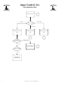
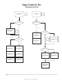
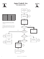
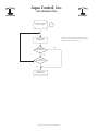
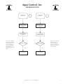
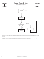
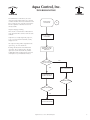
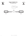
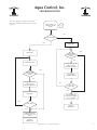
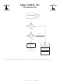
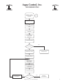
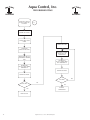
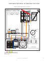
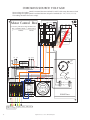
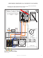
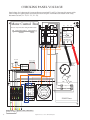
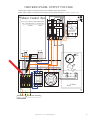
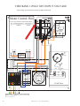
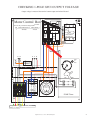
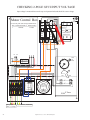
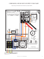
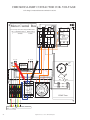
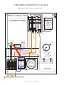
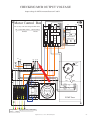
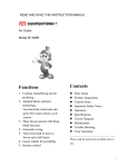
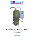
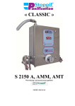
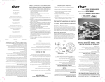
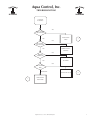
Aqua Control, Inc.
TROUBLESHOOTING
UNIT NOT
RUNNING
YES
OUTPUT VOLTS =
SOURCE VOLTS
INVESTIGATE
AMPS
NO
1
NO
INPUT VOLTS =
SOURCE VOLTS
CORRECT INPUT
VOLTAGE
YES
NO
TIMER SET
CORRECTLY?
YES
SET TIMER
NO
DID ANYTHING
TRIP?
OVERLOAD
3
INVESTIGATE GFCI’S
2
INVESTIGATE
HIGH AMPS
Aqua Control, Inc. Service Manual Chapter 8
1
Aqua Control, Inc.
TROUBLESHOOTING
INVESTIGATE AMPS
0 AMPS
1
HIGH AMPS
OUTPUT AMPS
LOW AMPS
DISCONNECT PUMP
CABLE
GOOD
LINE-TO-LINE
INVESTIGATE LOW
AMPS
INVESTIGATE HIGH
AMPS
4
3
SHORT / OPEN
YES
ISOLATE / REPLACE
FAULTY CABLE
5
2-WIRE MOTOR
YES
OVERLOAD IN
MOTOR TRIPPED
2
Aqua Control, Inc. Service Manual Chapter 8
Aqua Control, Inc.
TROUBLESHOOTING
INVESTIGATE
LOW AMPS
4
INVESTIGATE
AMPS
3
NO
YES
1-PHASE?
EXCESSIVE LINE
LOSS?
YES
INVESTIGATE
MOTOR CONTROL
BOX
6
1-PHASE?
YES
ADD BOOST
TRANSFORMER
NO
6
AERATOR?
INCREASE CABLE
GAUGE
INVESTIGATE
MOTOR CONTROL
BOX
YES
CHECK FOR
BLOCKED OUTLET
CHECK FOR
BLOCKED INLET
CHECK FOR
LOOSE IMPELLER
CHECK FOR
LOOSE PROPELLER
CHECK FOR
BROKEN MSE
CHECK FOR
BROKEN MSE
AERATOR?
CHECK FOR
BLOCKED INLET
CHECK FOR
BLOCKED OUTLET
CHECK FOR
LOCKED ROTOR
OR BEARINGS
High amps, (locked rotor amps) are only needed for very short periods of time, usually 1 second or less. Many multimeters will not register the high
amps.
Aqua Control, Inc. Service Manual Chapter 8
3
Aqua Control, Inc.
TROUBLESHOOTING
INVESTIGATE
MOTOR CONTROL
BOX
6
RED AMPS
HP
LOW
HIGH
1
1.3
43
2
2.6
51
3
6.0
84
5
10.8
121
INVESTIGATE
OVERLOADS
9
CHECK RED AMPS
Franklin motor control boxes have a complete
set of tests included on the inside of the motor
control box.
High amps, (locked rotor amps) are only needed
for very short periods of time, usually 1 second or
less. Many multimeters will not register the high
amps.
YES
HIGH, THEN LOW?
YES
GOOD
HIGH, THEN
STAYS HIGH?
7
YES
INVESTIGATE
RELAY COIL
HIGH, THEN 0?
LOW, THEN LOW?
8
4
INVESTIGATE
RELAY CONTACTS
INVESTIGATE
RELAY CONTACTS
8
INVESTIGATE
START CAPACITOR
10
Aqua Control, Inc. Service Manual Chapter 8
INVESTIGATE
RUN CAPACITOR
6
Aqua Control, Inc.
TROUBLESHOOTING
INVESTIGATE
GFCI
2
NO
TRIP WITHIN
A FEW MINUTES?
POWER OFF PANEL
POWER OFF PANEL
CHECK LOOSE
WIRES
CHECK LOOSE
WIRES
CHECK NEUTRAL TO
GROUND VOLTAGE
CHECK NEUTRAL TO
GROUND VOLTAGE
CHECK EACH HOT
TO NEUTRAL
CHECK EACH HOT
TO NEUTRAL
REMOVE PUMP
CABLE
REMOVE PUMP
CABLE
POWER ON PANEL
MEGG CABLE
NO
NO
LESS THAN 20 M
OHMS?
GFCI TRIPPED?
YES
YES
POWER OFF PANEL
ISOLATE LEAK TO
GROUND AFTER
PANEL
POWER OFF PANEL
13
MEGG CABLE TO
VERIFY LEAK TO
GROUND
11
12
ISOLATE LEAK TO
GROUND IN PANEL
ISOLATE LEAK TO
GROUND AFTER
PANEL
INVESTIGATE
NUISANCE TRIPPING
12
Aqua Control, Inc. Service Manual Chapter 8
5
Aqua Control, Inc.
TROUBLESHOOTING
INSOLATE / REPLACE
FAULTY CABLE
5
The next component may delineated by a splice,
a connector or a junction box. It may be a length
of cable, the motor lead or motor.
LOCATE NEXT
COMPONENT
ANOTHER
COMPONENT?
NO
YES
GOOD
LINE-TO-LINE?
YES
REPLACE LAST
COMPONENT
6
Aqua Control, Inc. Service Manual Chapter 8
Aqua Control, Inc.
TROUBLESHOOTING
INVESTIGATE
RELAY COIL
The resistance between
the Red wire, terminal
#2 and the Yellow connection, terminal #5
on the relay. Reading
should be between
4,500 Ohms and 7,500
Ohms.
7
INVESTIGATE
CONTACTS
REMOVE YELLOW
WIRE FROM TERMINAL
5 OF RELAY
REMOVE ORANGE
WIRE FROM TERMINAL
1 OF RELAY
SET OHMMETER TO
READ TO 20,000
OHMS
SET OHMMETER TO
LOWEST SETTING
GOOD READING?
GOOD READING?
NO
NO
REPLACE RELAY
REPLACE RELAY
Aqua Control, Inc. Service Manual Chapter 8
8
Read resistance between
the Orange wire, terminal #1 and the Red
connection, terminal #2.
Reading should be very
close to 0 Ohms.
7
Aqua Control, Inc.
TROUBLESHOOTING
INVESTIGATE
OVERLOAD
9
SET OHMMETER TO
LOWEST SETTING
OPEN LINE
GOOD READING?
NO
RESET OVERLOAD
REPLACE BOTH
OVERLOADS
To test an overload, read the resistance between the two soldered connections on the top of the overload. The overload should have a resistance of
0.5 Ohms or less. If the reading indicates open line the overloads must be reset and retested. Other readings indicate that both overloads should be
replaced.
Resetting an overload may be quite difficult. It may require pressing extremely hard to reset them. The only certain method for determining whether an
overload has been reset is to read the resistance between the two soldered connections at the top of the overload.
8
Aqua Control, Inc. Service Manual Chapter 8
Aqua Control, Inc.
TROUBLESHOOTING
For Franklin motor control boxes, the “start”
capacitor is large and black. The “run” capacitor
is smaller and silver. ACI motor control boxes will
have a single gray “run” capacitor. 2-wire motors
have the capacitors in the motor and are not
directly testable.
INVESTIGATE
CAPACITOR
10
Inspect for bulging or leaking.
There are two sets of terminals on the bottom of
each capacitor. Remove all wires from one of the
terminals.
Capacitance us usually designed by “Cap” “II”,
or ”I(-”. It is measured in microFarads, usually
displayed as “uF”.
VISUALLY INSPECT
CAPACITOR
The capacitor’s rating will be designated on the
capacitor e.g. 45 uF or 180-225 uF.
Readings should start low and climb toward
“open line”. The exception to this is the start
capacitor of a 5 HP unit. It will only climb to
15,000 Ohms. If the reading starts at “open line”
switch probes of your multimeter and retest.
REMOVE ALL WIRES
FROM ONE SET OF
CONTACTS
DOES MULTIMETER
TEST CAPACITANCE?
NO
YES
TEST CAPACITANCE
SET OHMMETER TO
HIGHEST SETTING
GOOD READING?
GOOD READING?
NO
NO
REPLACE CAPACITOR
Aqua Control, Inc. Service Manual Chapter 8
9
Aqua Control, Inc.
TROUBLESHOOTING
INVESTIGATE
LEAK TO GROUND
YES
ISOLATE 1-PHASE
11
NO
1-PHASE
14
10
ISOLATE 3-PHASE
15
Aqua Control, Inc. Service Manual Chapter 8
Aqua Control, Inc.
TROUBLESHOOTING
The use of a megger is strongly recommended.
The use of a multimeter will not detect most leaks
to ground.
ISOLATE LEAK TO
GROUND AFTER
PANEL
12
YES
USE MEGGER?
NO
POWER OFF
POWER OFF
ANOTHER
CONNECTION
POINT?
NO
YES
RECONNECT CABLE
DISCONNECT PUMP
CABLE AT NEXT
CONNECTION POINT
ANOTHER
CONNECTION
POINT?
NO
MEGG CABLE
TOWARD MOTOR
YES
DISCONNECT PUMP
CABLE AT NEXT
CONNECTION POINT
YES
LEAK TO
GROUND?
NO
POWER ON
LEAK TO GROUND
BETWEEN THIS POINT
AND LAST POINT
NO
GFCI TRIPS?
REPLACE
COMPONENT
YES
PROBLEM BETWEEN
LAST POINT AND THIS
POINT
REPLACE
COMPONENT
Aqua Control, Inc. Service Manual Chapter 8
11
Aqua Control, Inc.
TROUBLESHOOTING
INVESTIGATE
NUISANCE TRIPPING
13
NO
1-PHASE
YES
NO
200’ OF CABLE?
YES
DECREASE CABLE
LENGTH
POWER
FLUCTUATIONS
USE EP GFCI
THUNDERSTORMS
VFD
The use of an equipment-protection GFCI will remove the UL certification. Additionally, a leak-to-ground may result in electrocution.
12
Aqua Control, Inc. Service Manual Chapter 8
Aqua Control, Inc.
TROUBLESHOOTING
ISOLATE 1-PHASE
LEAK TO GROUND
IN PANEL
14
POWER OFF PANEL
CHECK FOR LOOSE
WIRES
CHECK FOR GOOD
NEUTRAL
DISCONNECT
OUTPUT WIRES
FROM GFCI
POWER ON PANEL
YES
GFCI TRIP?
POWER OFF PANEL
REPLACE GFCI
REATTACH WIRES TO
BOTTOM OF GFCI
TRACE OUTPUT
WIRES TO NEXT
COMPONENT
DISCONNECT OUTPUT WIRES FROM
COMPONENT
POWER ON PANEL
RECONNECT WIRES
TO OUTPUT OF
COMPONENT
NO
YES
GFCI TRIP?
Aqua Control, Inc. Service Manual Chapter 8
REPLACE
COMPONENT
13
Aqua Control, Inc.
TROUBLESHOOTING
INSOLATE 3-PHASE
LEAK TO GROUND
IN PANEL
15
POWER OFF PANEL
CHECK FOR LOOSE
WIRES
POWER OFF PANEL
CHECK FOR
GROUND NEUTRAL
RECONNECT WIRES
TO OUTPUT OF
COMPONENT
TRACE WIRES TO LAST
COMPONENT BEFORE
GFCI
DISCONNECT
OUTPUT WIRES FROM
NEXT COMPONENT
DISCONNECT
OUTPUT WIRES FROM
COMPONENT
POWER ON PANEL
POWER ON PANEL
GFCI TRIP?
YES
GFCI TRIP?
YES
REPLACE
COMPONENT
YES
REPLACE GFCI
14
Aqua Control, Inc. Service Manual Chapter 8
NO
CHECKING NEUTRAL TO GROUND VOLTAGE
Neutral to ground voltage must be very close to 0.
Motor Control Box
L1
L2
L3
G
For use only with same rating Franklin motor
Motor Prefix #
214508
HP Control Box Prefix #
2824085
1
ON
ON
PUMP GFI CB
LIGHT
GFI CB
OFF
20A
OFF
test
test 20A
N
L1 L2
N
Torque: ON
N 18 lb-in
OFF
DISCONNECT
SWITCH 60A
T1
T2
T3
R Y B
Time
set
knob
Lightning
Arrestor
ON
A1
OFF
A2
G
13
motor
switch
Timer
440 Volt
Push pins
towards center
for "ON" cycle
Light
Contactor
14
G R
Gnd R
Y B G Y B
Y
B
Pump Motor
230V, 7.1 Amps
Gnd N
LIGHTS
PUMP Timer
A2
H
Lights - 120V, 2000 watts
Aqua Control, Inc. Service Manual Chapter 8
15
CHECKING SOURCE VOLTAGE
Source voltage for 1-phase panels is measured between terminals L1 and L3 of the rotary disconnect switch.
Source voltage for 3-phase panels is measured between each pair of terminals (L1 - L2, L1- L3, L2 - L3).
The readings should be the source voltage.
Motor Control Box
L1
L2
L3
G
For use only with same rating Franklin motor
Motor Prefix #
214508
HP Control Box Prefix #
2824085
1
ON
ON
PUMP GFI CB
LIGHT
GFI CB
OFF
20A
OFF
test
test 20A
N
L1 L2
N
N
Torque: ON
18 lb-in
OFF
DISCONNECT
SWITCH 60A
T1
T2
T3
R Y B
Time
set
knob
Lightning
Arrestor
ON
A1
A2
G
13
motor
switch
Timer
440 Volt
Push pins
towards center
for "ON" cycle
Light
Contactor
14
G R
Gnd R
Y B G Y B
Y
B
Pump Motor
230V, 7.1 Amps
16
OFF
Gnd N
LIGHTS
PUMP Timer
A2
H
Lights - 120V, 2000 watts
Aqua Control, Inc. Service Manual Chapter 8
CHECKING INDIVIDUAL SOURCE VOLTAGES
Individual source voltage is measured between each input terminal with a wire and Neutral.
The readings at L1 and L3 MUST be 1/2 source voltage.
Motor Control Box
L1
L2
L3
G
For use only with same rating Franklin motor
Motor Prefix #
214508
HP Control Box Prefix #
2824085
1
ON
ON
PUMP GFI CB
LIGHT
GFI CB
OFF
20A
OFF
test
test 20A
N
L1 L2
N
N
Torque: ON
18 lb-in
OFF
DISCONNECT
SWITCH 60A
T1
T2
T3
R Y B
Time
set
knob
Lightning
Arrestor
ON
A1
OFF
A2
G
13
motor
switch
Timer
440 Volt
Push pins
towards center
for "ON" cycle
Light
Contactor
14
G R Y B G Y B
Gnd R
Y
B
Pump Motor
230V, 7.1 Amps
Gnd N
LIGHTS
PUMP Timer
A2
H
Lights - 120V, 2000 watts
Aqua Control, Inc. Service Manual Chapter 8
17
CHECKING PANEL VOLTAGE
Panel voltage for 1-phase panels is measured between terminals T1 and T3 of the rotary disconnect switch.
Panel voltage for 3-phase panels is measured between each pair of terminals at the bottom of the rotary
disconnnect switch (T1 - T2, T1 - T3, T2 - T3) .
Motor Control Box
L1
L2
L3
For use only with same rating Franklin motor
HP Control Box Prefix # Motor Prefix #
214508
2824085
1
ON
ON
PUMP GFI CB
LIGHT
GFI CB
OFF
20A
OFF
test
test 20A
N
L1 L2
N
N
Torque: ON
18 lb-in
OFF
DISCONNECT
SWITCH 60A
T1
T2
T3
R Y B
Time
set
knob
Lightning
Arrestor
ON
A1
13
motor
switch
Timer
440 Volt
Push pins
towards center
for "ON" cycle
Light
Contactor
14
G R
Y B G Y B
Gnd R
Y
Pump Motor
230V, 7.1 Amps
18
OFF
A2
G
B
Gnd N
G
LIGHTS
PUMP Timer
A2
H
Lights - 120V, 2000 watts
Aqua Control, Inc. Service Manual Chapter 8
CHECKING PANEL OUTPUT VOLTAGE
1-Phase output voltage is measured between Yellow and Black pump cable terminals.
3-Phase output voltage is measured between each pair of pump cable terminals (T1 - T2, T1 - T3, T2 - T3).
Motor Control Box
L3
L1
For use only with same rating Franklin motor
HP Control Box Prefix # Motor Prefix #
214508
2824085
1
ON
ON
PUMP GFI CB
LIGHT
GFI CB
OFF
20A
OFF
test
test 20A
N
L1 L2
G
Torque: ON
N 18 lb-in
OFF
DISCONNECT
SWITCH 60A
N
R Y B
Time
set
knob
Lightning
Arrestor
ON
A1
OFF
A2
G
13
motor
switch
Timer
440 Volt
Push pins
towards center
for "ON" cycle
Light
Contactor
14
G R
Y B G Y B
Gnd R
Y
T1
B
Gnd N
LIGHTS
A2
PUMP Timer
H
T2 T3
Pump Motor
230V, 7.1 Amps
Lights - 120V, 2000 watts
Aqua Control, Inc. Service Manual Chapter 8
19
CHECKING 1-POLE GFCI INPUT VOLTAGE
Input voltage is measured between the top input and Neutral.
Motor Control Box
L3
L1
For use only with same rating Franklin motor
Motor Prefix #
214508
HP Control Box Prefix #
2824085
1
ON
ON
PUMP GFI CB
LIGHT
GFI CB
OFF
20A
OFF
test
test 20A
N
L1 L2
Torque: ON
N 18 lb-in
OFF
DISCONNECT
SWITCH 60A
N
R Y B
Time
set
knob
Lightning
Arrestor
ON
A1
13
motor
switch
Timer
440 Volt
Push pins
towards center
for "ON" cycle
Light
Contactor
14
G R
Y B G Y B
Gnd R
Y
Pump Motor
230V, 7.1 Amps
20
OFF
A2
G
B
Gnd N
G
LIGHTS
PUMP Timer
A2
H
Lights - 120V, 2000 watts
Aqua Control, Inc. Service Manual Chapter 8
CHECKING 1-POLE GFCI OUTPUT VOLTAGE
Output voltage is measured between the bottom output terminal and Neutral.
Motor Control Box
L3
L1
For use only with same rating Franklin motor
Motor Prefix #
214508
HP Control Box Prefix #
2824085
1
ON
ON
PUMP GFI CB
LIGHT
GFI CB
OFF
20A
OFF
test
test 20A
N
L1 L2
G
Torque: ON
N 18 lb-in
OFF
DISCONNECT
SWITCH 60A
N
R Y B
Time
set
knob
Lightning
Arrestor
ON
A1
OFF
A2
G
13
motor
switch
Timer
440 Volt
Push pins
towards center
for "ON" cycle
Light
Contactor
14
G R Y B G Y B
Gnd R
Y
B
Pump Motor
230V, 7.1 Amps
Gnd N
LIGHTS
A2
PUMP Timer
H
Lights - 120V, 2000 watts
Aqua Control, Inc. Service Manual Chapter 8
21
CHECKING 2-POLE GFCI INPUT VOLTAGE
Input voltage is measured between the top two input terminals and should be source voltage.
Motor Control Box
L3
L1
For use only with same rating Franklin motor
Motor Prefix #
214508
HP Control Box Prefix #
2824085
1
ON
ON
PUMP GFI CB
LIGHT
GFI CB
OFF
20A
OFF
test
test 20A
N
L1 L2
N
Torque: ON
18 lb-in
OFF
DISCONNECT
SWITCH 60A
N
R Y B
Time
set
knob
Lightning
Arrestor
ON
A1
13
motor
switch
Timer
440 Volt
Push pins
towards center
for "ON" cycle
Light
Contactor
14
Gnd R
Y B G Y B
Y
B
Pump Motor
230V, 7.1 Amps
22
OFF
A2
G
G R
Gnd N
G
LIGHTS
PUMP Timer
A2
H
Lights - 120V, 2000 watts
Aqua Control, Inc. Service Manual Chapter 8
CHECKING 2-POLE GFCI OUTPUT VOLTAGE
Output voltage is measured between the bottom two output terminals.
Motor Control Box
L3
L1
For use only with same rating Franklin motor
Motor Prefix #
214508
HP Control Box Prefix #
2824085
1
ON
ON
PUMP GFI CB
LIGHT
GFI CB
OFF
20A
OFF
test
test 20A
N
L1 L2
G
Torque: ON
N 18 lb-in
OFF
DISCONNECT
SWITCH 60A
N
R Y B
Time
set
knob
Lightning
Arrestor
ON
A1
OFF
A2
G
13
motor
switch
Timer
440 Volt
Push pins
towards center
for "ON" cycle
Light
Contactor
14
G R
Y B G Y B
Gnd R
Y
B
Pump Motor
230V, 7.1 Amps
Gnd N
LIGHTS
A2
PUMP Timer
H
Lights - 120V, 2000 watts
Aqua Control, Inc. Service Manual Chapter 8
23
CHECKING LIGHT CONTACTOR COIL VOLTAGE
Coil voltage is measured between terminals A1 and A2.
Motor Control Box
L3
L1
For use only with same rating Franklin motor
HP Control Box Prefix # Motor Prefix #
214508
2824085
1
ON
ON
PUMP GFI CB
LIGHT
GFI CB
OFF
20A
OFF
test
test 20A
N
L1 L2
N
Torque: ON
18 lb-in
OFF
DISCONNECT
SWITCH 60A
N
R Y B
Time
set
knob
Lightning
Arrestor
ON
A1
13
motor
switch
Timer
440 Volt
Push pins
towards center
for "ON" cycle
Light
Contactor
14
G R
Y B G Y B
Gnd R
Y
Pump Motor
230V, 7.1 Amps
24
OFF
A2
G
B
Gnd N
G
LIGHTS
PUMP Timer
A2
H
Lights - 120V, 2000 watts
Aqua Control, Inc. Service Manual Chapter 8
CHECKING LIGHT CONTACTOR OUTPUT VOLTAGE
Output voltage is measured between each output terminal and Neutral.
Motor Control Box
L3
L1
For use only with same rating Franklin motor
Motor Prefix #
214508
HP Control Box Prefix #
2824085
1
ON
ON
PUMP GFI CB
LIGHT
GFI CB
OFF
20A
OFF
test
test 20A
N
L1 L2
N
G
Torque: ON
18 lb-in
OFF
DISCONNECT
SWITCH 60A
N
R Y B
Time
set
knob
Lightning
Arrestor
ON
A1
OFF
A2
G
13
motor
switch
Timer
440 Volt
Push pins
towards center
for "ON" cycle
Light
Contactor
14
G R
Gnd R
Y B G Y B
Y
B
Pump Motor
230V, 7.1 Amps
Gnd N
LIGHTS
PUMP Timer
A2
H
Lights - 120V, 2000 watts
Aqua Control, Inc. Service Manual Chapter 8
25
CHECKING MCB INPUT VOLTAGE
Input voltage is measured between terminals L1 and L2
Motor Control Box
L3
L1
For use only with same rating Franklin motor
Motor Prefix #
214508
HP Control Box Prefix #
2824085
1
ON
ON
PUMP GFI CB
LIGHT
GFI CB
OFF
20A
OFF
test
test 20A
N
L1 L2
Torque: ON
N 18 lb-in
OFF
DISCONNECT
SWITCH 60A
N
R Y B
Time
set
knob
Lightning
Arrestor
ON
A1
13
motor
switch
Timer
440 Volt
Push pins
towards center
for "ON" cycle
Light
Contactor
14
G R Y B G Y B
Y
B
Pump Motor
230V, 7.1 Amps
26
OFF
A2
G
Gnd R
Gnd N
G
LIGHTS
PUMP Timer
A2
H
Lights - 120V, 2000 watts
Aqua Control, Inc. Service Manual Chapter 8
CHECKING MCB OUTPUT VOLTAGE
Output voltage for MCB is measured between Y and B
Motor Control Box
L3
L1
For use only with same rating Franklin motor
Motor Prefix #
214508
HP Control Box Prefix #
2824085
1
ON
ON
PUMP GFI CB
LIGHT
GFI CB
OFF
20A
OFF
test
test 20A
N
L1 L2
G
Torque: ON
N 18 lb-in
OFF
DISCONNECT
SWITCH 60A
N
R Y B
Time
set
knob
Lightning
Arrestor
ON
A1
OFF
A2
G
13
motor
switch
Timer
440 Volt
Push pins
towards center
for "ON" cycle
Light
Contactor
14
G R Y B G Y B
Gnd R
Y
B
Pump Motor
230V, 7.1 Amps
Gnd N
LIGHTS
A2
PUMP Timer
H
Lights - 120V, 2000 watts
Aqua Control, Inc. Service Manual Chapter 8
27