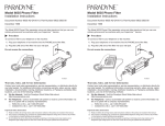
1
Thank you for purchasing a CAM Superline trailer.
CAM Superline, Inc. manufactures durable,
dependable dump trailers, construction trailers and
pickup truck dump inserts.
Built for the long haul, CAM Superline trailers
deliver consistent performance today and for years
to come. Not only are you investing in a superior
trailer, you're backed by CAM's knowledgeable
service network and two year warranty.
This manual is designed to provide information for
you to safely understand, use, maintain and service
your CAM Superline trailer.
It is essential that you read this manual prior to
loading or towing your trailer and follow all
safety precautions and instructions.
Visit us online at
www.camsuperline.com
1
Safety Information
Vin tag information
Trailer towing guide
Hazards from modifying your trailer
Driving too fast
Failure to adjust handling while towing a trailer
Using an adequate tow vehicle and hitch
Securing safety chains & electrical cables
Attaching & testing electric breakaway system
Incorrect use of breakaway
Unsafe tires, lug nuts or wheels
Overloading
Tire Safety Information
Trailers less than and over 10,000 lb. GVWR
Safety first-basic tire maintenance
Finding your vehicle’s recommended
Tire pressure & load limits
Checking tire pressure & tire size
Tire tread, tire repair, tire fundamentals & tire safety tips
4
5
6
6
6
6
7
8
8
9
10
11
12
12
13
13
14
Coupling to the Tow Vehicle
Coupling and uncoupling the trailer
Various hitch designs
Ball coupler—Bumper pull trailer
Pintle ring - Bumper pull trailer
Uncoupling a bumper pull trailer
Adjust bumper pull trailer hitch height
Gooseneck trailer with ball receiver
15
15
15-17
17-18
19
19
20-23
Breaking in a new trailer
Pre-tow checklist
Making regular stops
Retighten lug nuts at first 10, 25 & 50 miles
Adjusting brake shoes at first 200 miles
Synchronizing the brake system
24
24
24
25
25
Table of Contents
Trailer Connection to Tow Vehicle
Ball coupler, pintle hook & gooseneck
Fifth wheel kingpin
Jack or landing leg
Lights and signals
Tires
Wheels, bearings & lug nuts
Lug nut torque
Electrical connections - 7 way RV plug & 6 way round plug
26
27
27
27
27
28
29
30-33
Hydraulics
Hydraulic fluid and reservoir
Troubleshooting your hydraulic system
Pump diagram
Loading & Unloading a Flatbed Trailer
Preparing the trailer for loading
Checking tongue weight
Loading cargo & securing cargo
Loading the trailer
Ramp Types, Ladder or wood filled and landscape ramps,
& Removable ramps
2
34
34
35
36
36
36
37
38
39
Loading the trailer
Slide-out ladder ramps & landscape gate/ramps
Hazards for dump trailers
Loading fixed loads & Rear loading equipment
Prepare trailer for loading
Loading and unloading bulk materials
Unload bulk material using the spreader gate
Unload bulk material using the split barn door &
combination spreader/split barn door gate
Hydraulic Reservoir & Components
Safety Prop
Securing the cargo
Lubrication points
Slide-out ramps
Accessories
Accessory battery & battery charger
DC Hydraulic power unit
40
41
41
41
42
43
44
44-45
45-46
47
48
48-49
49
49
49
50
50
51
Inspection, Service & Maintenance Charts
Inspection and service before each use
Inspection and service every 6months or 6,000 miles
Inspection and service every 12 months or 12,000 miles
Axle bolts, frame, suspension & structure
Trailer structure & Fasteners and frame members
Welds
Trailer brakes - electric
Brake shoes and drums & Manually adjusting brake shoes
Brakes - electric
Breakaway brakes
Tow vehicle operated electric brakes
Magnets for all electric brakes
Trailer brakes - surge
Hydraulic surge brakes & master cylinder bleeding
Trailer connection to tow vehicle
Bumper pull ball coupler & pintle
Gooseneck ball receiver
Landing gear
Lights & signals
Wheels & tires
Tire wear diagnostic chart
Wheel bearings & Oil batch axles
Lug nuts
52
53
53
54
54
55
55
55
56
56
56
56
57
57-58
58
58-59
59
59
59
60
61
62
63
Storage preparation
After prolonged storage—inspection procedure
Trip preparation checklist
Maintenance schedule
64
64
65
66
67
68
69-71
Storage
Warranty
Reporting Safety Defects
Service Record
3
Table of Contents
Loading & Unloading a Tilt Trailer
Loading & Unloading a Dump Trailer
Safety Information
An owner’s manual that provides general trailer information cannot cover all the
specific details necessary for proper combination of every trailer, tow
vehicle and hitch. Follow all of the safety precautions and instructions in this
manual to ensure safety of persons, cargo and satisfactory life of the trailer.
Therefore, you must read, understand and follow the instructions given by the
tow vehicle and trailer hitch manufacturers.
Loss of control of the trailer or trailer/tow vehicle combination can result in
serious injury or death. The most common causes for loss of control of the trailer
are:
Driving too fast for the conditions
Inadequate tow vehicle or towing hitch
Trailer improperly coupled to the hitch
Overloading the trailer or loading the trailer unevenly
No braking on the trailer
Not maintaining proper tire pressure
Not maintaining proper lug nut torque
Not properly maintaining the trailer structure
Vin Tag Information
The trailer ―VIN Tag‖ or Vehicle Identification Number, is located on the front
driver’s side of the trailer. The ―VIN Tag‖ contains the following critical safety
information for the use of your trailer.
Safety Information
GAWR: The maximum gross weight that an axle can support. It is the lowest
of the axle, wheel or tire rating.
GVWR: The maximum allowable gross weight of the trailer and its contents.
The gross weight of the trailer includes the weight of the trailer and all of the
items on it, such as cargo.
PSI: The tire pressure (Pounds per Square Inch)
Empty Weight: Some information that comes with the trailer (such as the
Manufacturer’s Statement of Origin) is not a reliable source for ―empty‖ weight.
The shipping documents list standard weights and your trailer may be equipped
with options. To determine the ―empty‖ weight of your trailer, weigh it on an
axle scale. To find the weight of the trailer using an axle scale, you must know
the axle weights of your tow vehicle without the trailer coupled. Some of the
trailer weight will be transferred from the trailer to the tow vehicle axles and an
axle scale weighs all axles, including the tow vehicle axles.
4
Driving a vehicle with a trailer in tow is vastly different from driving the same
vehicle without a trailer in tow. Acceleration, maneuverability and braking are all
diminished with a trailer in tow.
Recheck the load tie downs to make sure the load will not shift during
towing.
Before towing, check coupling, safety chains, breakaway system, tires,
wheels and lights
Check lug nut torque
Check coupler or pintle tightness after towing 50 miles.
Adjust the brake controller to engage the trailer brakes before the tow vehicle
brakes. Your dealer can assist you by making this adjustment.
Use your mirrors to verify that you have room to change lanes or pull into
traffic.
Use your turn signals well in advance.
Allow plenty of stopping space for your trailer and tow vehicle.
Do not drive so fast that the trailer begins to sway due to excess speed.
Allow plenty of room for passing. A rule of thumb is that the passing
distance with a trailer is 4 times the passing distance without a trailer.
Shift your automatic transmission into a lower gear for city driving.
Use lower gears for climbing and descending grades.
Do not ride the brakes while descending grades; they may get so hot that they
stop working. Then you will potentially have a runaway tow vehicle and
trailer.
To conserve fuel, don’t use full throttle to climb a hill. Instead, build speed
on the approach.
Slow down for bumps in the road. Take your foot off the brake when
crossing the bump.
Do not brake while in a curve unless absolutely necessary. Instead, slow
down before you enter the curve and power throughout the curve.
This way, the towing vehicle remains ―in charge‖
Do not apply the brakes to correct extreme trailer swaying. Continued pulling
of the trailer and even slight acceleration will provide a stabilizing force.
Make regular stops, about once each hour and confirm that:
º The coupler is secure to the hitch and is locked.
º Electrical connectors are made.
º There is appropriate slack in the safety chains and breakaway
switch cable.
º The tires are not visibly low on pressure.
º The cargo is secure and in good condition.
5
Safety Information
Trailer Towing Guide Checklist
Hazards from Modifying your Trailer
Essential safety items can be damaged by altering your trailer. Before making
any alteration to your trailer, contact your dealer. Structural modifications will
void your warranty.
Driving Too Fast
With ideal road conditions, the maximum speed when safely towing a trailer is
60 M.P.H.
CAUTION
Driving too fast for conditions can result in loss of control
and cause serious injury or death.
Failure to Adjust Handling while Towing a Trailer
When towing a trailer, you will have decreased acceleration, increased stopping
distance and increased turning radius. In addition, you will need a longer
distance to pass, due to slower acceleration and increased length.
Anticipate the trailer swaying. Swaying is the trailer’s reaction to the air
pressure wave caused by passing trucks and buses. Continued pulling of the
trailer provides a stabilizing force to correct swaying. Do not apply the
brakes to correct trailer swaying.
Use a lower gear when driving down steep or long grades. Use the engine
and transmission as a brake. Do not ride the brakes, as they can overheat
and become ineffective.
Safety Information
Use an Adequate Tow Vehicle and Hitch
If the vehicle or hitch is not properly selected and matched to the GVWR of your
trailer, you can cause an accident that could lead to serious injury or death.
If you already have a tow vehicle, know your vehicle tow rating and make
certain the trailer’s rated capacity is less than or equal to the tow vehicle’s rated
towing capacity. If you already have a trailer, make certain that the tow rating of
the tow vehicle is equal to or greater than that of the trailer.
6
Visually inspect the safety chains and hooks for wear or damage. Replace
worn or damaged safety chains and hooks before towing.
Secure the safety chains so that they:
º Criss-cross underneath the hitch with enough slack to permit turning
and to hold the tongue up above the ground if the trailer comes loose.
º Secure the safety chains to the frame of the tow vehicle. Do not secure
the safety chains to the interchangeable part of the hitch assembly.
CAUTION
Improperly attached safety chains can result in loss of
control of the trailer and tow vehicle.
This can result in serious injury or death if the trailer
unhooks from the tow vehicle.
Connecting the Electrical Cables
Connect the trailer lights to the tow vehicle’s electrical system using the electrical
connectors. Be sure that the electric brakes and all of the lights on your trailer are
functioning properly before towing the trailer. The electric brakes and lights on a
trailer are controlled by a connection to the tow vehicle.
If the trailer has electric brakes, your tow vehicle should have an electric brake
controller that sends power to the trailer brakes. Before towing the trailer on the
road, you must operate the brake controller while trying to pull the trailer in order
to confirm that the electric brakes operate. While towing the trailer at less than
5mph, manually operate the electric brake controller in the tow vehicle cab.
You should feel the operation of the trailer brakes.
CAUTION
Improper electrical connection between the tow vehicle
and the trailer will result in inoperable lights and electric
brakes, and can lead to collision.
Before each tow, check:
All lights and turn signals work.
The electric brakes work by operating the brake
controller inside the tow vehicle.
7
Safety Information
Securing the Safety Chains
Attaching and Testing Electric Breakaway System
If the ball coupler, pintle, or hitch fails, a properly connected and working
breakaway system will apply electric brakes on the trailer.
The breakaway brake system may be fitted with a charging facility that draws
power from the tow vehicle. If the electrical system on your tow vehicle does not
provide power to the breakaway battery, you must periodically charge the battery
to keep the breakaway brake system in working order.
CAUTION
Disconnect the trailer plug before testing breakaway unit.
Failure to do so will result in severe damage to electric
brake control.
Connect the breakaway cable to the tow vehicle so that the cable will be
pulled out before all of the slack in the safety chains are taken up. Do not
connect the cable to the safety chain or any part of the hitch. This would
keep the breakaway system from operating when needed.
Remove the cable pin from the switch and test tow the trailer, at less than
5 mph. You should feel the trailer resisting being towed, but the wheels will
not necessarily be locked. If the brakes do not function, do not tow the trailer
until the brakes are repaired.
Immediately replace the cable pin. The breakaway system battery will
discharge rapidly when the cable pin is removed.
Incorrect Use of Breakaway System
Safety Information
Do not tow the trailer with the breakaway system ON because the brakes will
overheat which can result in permanent brake failure. Do not use the breakaway
system as a parking brake.
If you do not use the trailer for three or more months, or during winter months:
Store the battery indoors.
Charge the battery every three months.
CAUTION
An ineffective or inoperative breakaway system can result
in a runaway trailer, leading to serious injury or death.
Before towing the trailer, test the function of the breakaway
system. If the breakaway system is not working, do not tow
the trailer; have it serviced or repaired.
8
It is essential to inspect the trailer tires before each tow.
Improper tire pressure causes an unstable trailer and can result in a tire blowout
and loss of control. Therefore, before each tow you must check tire pressure.
Tire pressure must be checked when tires are cold. Allow three hours for tires to
cool down after driving before checking tire pressure. NOTE: Trailer tires may
require higher pressures than passenger vehicle tires.
Since trailer wheels and lug nuts are subjected to greater side loads than
automobile wheels, they are more prone to loosen. Before each tow, check to
make sure they are tight. Lug nuts are prone to loosen after first being assembled.
CAUTION
Improper tire pressure can result in a blowout and loss of
control, which can lead to serious injury or death.
Be sure tires are inflated to pressure indicated on side wall
before towing trailer.
When driving a new trailer (or after wheels have been remounted), check to make
sure the lug nuts are tight and re-torque after the first 10, 25 and 50 miles of
driving and before each tow thereafter. Improper lug nut torque can cause a wheel
to part from the trailer. Either of these can lead to serious injury or death.
The proper tightness (torque) for lug nuts are listed below. Use a torque wrench to
tighten the lug nuts. If you do not have a torque wrench, use a lug wrench and
tighten the lug nuts as much as you can. Then have a service garage or trailer
dealer tighten the lug nuts to the proper torque.
Lug Nut Torque - Steel Wheels
Axle Rating (Lbs.)
Stud Size
Torque - Ft. lbs.
3,500
1/2 inch
90 to 120
6,000 6 Lug
1/2 inch
90 to 120
6,000 & 7,000 8 Lug
9/16 inch
90 to 120
8,000
5/8 in. flanged
275 to 325
10,000
5/8 inch
190 to 210
12,000
5/8 inch
190 to 210
22,500
M22 x 1.5
Swivel Flange
450 to 500
9
Safety Information
Unsafe Tires, Lug Nuts or Wheels
Overloading
The total weight of the load you put in or on the trailer, plus the empty weight of
the trailer itself, must not exceed the trailer’s Gross Vehicle Weight Rating
(GVWR). If you do not know the empty weight of the trailer, you must weigh it
at a commercial scale. In addition, you must distribute the load on the trailer in
such a way that the load on any tire or axle does not exceed the tire load rating or
the Gross Axle Weight Rating (GAWR).
Unsafe Load Distribution
CAUTION
An overloaded trailer can result in loss of control of the
trailer, leading to serious injury or death.
Uneven load distribution can cause tire, wheel, axle, or structural failure. Be sure
your trailer is properly loaded. Improper front / rear load distribution can lead to
an unstable trailer or poor tow vehicle handling.
A proper weight distribution is equal, right to left and creates a tongue weight that
is in the proper range for stable trailer handling. For tandem and triple axle
trailers it is necessary to know or check that no axle is overloaded.
In the table below, the second column notes the rule of thumb percentage of total
weight of the trailer plus its cargo (Gross Vehicle Weight) that should appear on
the tongue of the trailer. For example, a trailer with a gooseneck hitch, with a
loaded weight of 12,000 lbs., should have 20-25% of 12,000 lbs. on the tongue
(2,400 to 3,000 lbs.).
Tongue weight as a percentage of loaded trailer weight
Type of Hitch
Percentage
Safety Information
Bumper Hitch
Gooseneck Hitch
Fifth Wheel Hitch
10-15%
20-25%
20-25%
Towing stability also depends on keeping the center of gravity as low as possible.
Load heavy items on the floor and over the axles, but do not exceed the axle load
rating (GAWR). When loading additional items, be sure to maintain even
side-to-side weight distribution and proper tongue weight.
CAUTION
Improper load distribution can result in loss of control of
the trailer, leading to serious injury or death.
10
The portion of the User’s Manual contains tire safety required by 49 CFR575.6.
Trailer tires may be worn out, even though they still have plenty of tread left.
This is because trailer tires have to carry a lot of weight all the time, even when
not in use. It is actually better for the tire to be rolling down the road than to be
idle. During use, the tire releases lubricants that are beneficial to tire life.
Using the trailer tires often helps prevent flat spots from developing.
Determining the load limits of a trailer includes more than understanding the load
limits of the tires alone. On all trailers there is a Federal Certification / VIN label
that is located on the forward half of the left (road) side of the unit.
This certification / VIN label will indicate the trailer’s Gross Vehicle Weight
Rating (GVWR). This is the most weight the fully loaded trailer can weigh.
It will also provide the Gross Axle Weight Rating (GAWR). This is the most a
particular axle can weigh. If there are multiple axles, the GAWR of each axle will
be provided.
If your trailer has a GVWR of 10,000 pounds or less, there is a vehicle placard
located in the same location as the certification label described above.
This placard provides tire and loading information. In addition, this placard will
show a statement regarding maximum cargo capacity. Cargo can be added to the
trailer, up to the maximum weight specified on the placard. The combined weight
of the cargo is provided as a single number. In any case, remember; the total
weight of a fully loaded trailer can not exceed the stated GVWR.
When loading your cargo, be sure it is distributed evenly to prevent overloading
front to back and side to side. Heavy items should be placed low and as close to
the axle positions as reasonable. Too many items on one side may overload a tire.
The best way to know the actual weight of the trailer is to weigh it at a public
scale. Talk to your dealer to discuss the weighing methods needed to capture the
various weights related to the trailer. This would include the weight empty or
unloaded, weights per axle, wheel, hitch or king-pin, and total weight.
Excessive loads and/or under inflation cause tire overloading and, as a result,
abnormal tire flexing occurs. This situation can generate an excessive amount of
heat within the tire. Excessive heat may lead to tire failure. It is the air pressure
that enables a tire to support the load, so proper inflation is critical. The proper air
pressure may be found on the Certification / VIN label and/or on the tire placard.
This value should never exceed the maximum cold inflation pressure stamped on
the tire.
11
Tire Safety Information
Tire Safety Information
Trailers 10,000 Pounds GVWR or Less
Tire and Loading Information Placard - Figure 1-1
Locate the statement, ―The weight of cargo should never exceed XXX KG or
XXX lbs.,‖ on your vehicle’s placard. See Figure 1-1.
This figure equals the available amount of cargo and luggage load capacity.
Determine the combined weight of luggage and cargo being loaded on the
vehicle. That weight may not safely exceed the available cargo and luggage
load capacity.
Subtract the empty weight of your trailer from the GVWR stated on the VIN
label. That weight is the maximum available cargo capacity of the trailer and
may not be safely exceeded.
The trailer’s placard refers to the Tire Information Placard attached adjacent to or
near the trailer’s VIN (certification) label at the left front of the trailer.
Tire Safety Information
The National Traffic Safety Administration (NHTSA) has published a brochure
(DOT HS 809 361) that discusses all aspects of tire safety, as required by CFR
575.6. This brochure is reproduced in part below. It can be obtained and
downloaded from NHTSA, free of charge, from the following website:
http://www.nhtsa.dot.gov/cars/rules/TireSafety/ridesonit/tires_index.html
Trailers Over 10,000 Pounds GVWR
(NOTE: These trailers are not required to have a tire information placard on the
trailer and may not have one installed)
Safety First-Basic Tire Maintenance
Properly maintained tires improve the steering, stopping, traction, and
load-carrying capability of your vehicle. Under-inflated tires and overloaded
vehicles are a major cause of tire failure. Therefore, as mentioned above, to avoid
flat tires and other types of tire failure, you should maintain proper tire pressure,
observe tire and vehicle load limits, avoid road hazards and regularly inspect your
tires.
12
Tire information placards and vehicle certification labels contain information on
tires and load limits. These labels indicate vehicle manufacturer’s information
including:
Recommended tire size.
Recommended tire inflation pressure.
Vehicle capacity weight (VCW - the maximum cargo weight a vehicle is
designed to carry).
Front and rear gross axle weight ratings (GAWR - the maximum weight the
front axle systems are designed to carry).
Checking Tire Pressure
It is important to check your vehicle’s tire pressure at least once a month for the
following reasons:
Most tires may naturally lose air over time.
Tires can lose air suddenly if you drive over a pothole or other object or if
you strike the curb when parking.
With radial tires, it is usually not possible to determine under-inflation by
visual inspection.
For convenience, purchase a tire pressure gauge to keep in your vehicle.
The recommended tire inflation pressure that vehicle manufacturers provide
reflects the proper psi when a tire is cold. The term cold does not relate to the
outside temperature. Rather, a cold tire is one that has not been driven on for at
least three hours. When you drive, your tires get warmer, causing the air pressure
within them to increase. To get an accurate reading, measure tire pressure when
the tires are cold or compensate for the extra pressure in warm tires.
Tire Size
To maintain tire safety, purchase new tires that are the same size as the vehicle’s
original tires or another size recommended by the manufacturer. Look at the tire
information placard, the owner’s manual or the sidewall of the tire to find this
information. If you have any doubt about the correct size to choose, consult with
the tire dealer.
13
Tire Safety Information
Finding Your Vehicle’s Recommended Tire Pressure and
Load Limits
Tire Tread
The tire tread provides the gripping action and traction that prevent your vehicle
from slipping or sliding, especially when the road is wet or icy. In general, tires
are not safe and should be replaced when the tread is worn down to 1/16 of an
inch. Tires have built-in treadwear indicators that let you know when it is time to
replace your tires. These indicators are raised sections spaced intermittently in the
bottom of the tread grooves. When they appear ―even‖ with the outside of the
tread, it is time to replace your tires.
Tire Repair
The proper repair of a punctured tire requires a plug for the hole and a patch for
the area inside the tire that surrounds the puncture hold. Punctures through the
tread can be repaired if they are not too large, but punctures to the sidewall should
not be repaired. Tires must be removed from the rim to be properly inspected
before being plugged and patched.
Tire Fundamentals
Federal law requires tire manufacturers to place standardized information on the
sidewall of all tires. This information identifies and describes the fundamental
characteristics of the tire and also provides a tire identification number for safety
standard certification and in case of a recall.
Tire Safety Information
Tire Safety Tips
Preventing Tire Damage
Slow down if you have to go over a pothole or other objects in the road.
Do not run over curbs or other foreign objects in the roadway, and try not to
strike the curb when parking.
Tire Safety Checklist
Check tire pressure regularly (at least once a month), including the spare.
Inspect tires for uneven wear patterns on the tread, cracks, foreign objects or
other signs of wear or trauma.
Make sure your tire valves have valve caps.
Check tire pressure before going on a long trip.
Do not overload your vehicle. Check the Tire Information and Loading
Placard or User’s Manual for the maximum recommended load for the
vehicle.
14
A secure coupling of the trailer to the tow vehicle is essential. A loss of coupling
may result in serious injury or death. Therefore, you must understand and follow
all of the instructions. The following parts are involved in making a secure
coupling between the trailer and the tow vehicle:
Ball Coupler or Pintle - Device on the tongue of the trailer that connects the
hitch on the tow vehicle.
Hitch - Device on the tow vehicle that supports the weight of the trailer
tongue and pulls the trailer. The ball coupler or pintle attaches to the hitch.
Safety Chains - If the coupler connection comes loose, the safety chains can
keep the trailer attached to the tow vehicle. With properly rigged safety
chains, it is possible to keep the tongue of the trailer from digging into the
road pavement, even if the ball coupler or pintle to hitch connection comes
apart.
Breakaway Switch - If the coupler connection comes loose, the breakaway
switch can actuate emergency electrical brakes on the trailer. The breakaway
switch must be rigged to the tow vehicle with appropriate slack that will
activate the switch if the coupler connection comes loose.
Jack - Device on the trailer that is used to raise and lower the hitch. The jack
is also referred to as the ―landing gear‖.
Various Hitch Designs
Trailers are produced with a variety of hitch devices. One of the following
sections will pertain to your trailer.
Bumper pull; ball coupler or pintle ring
Gooseneck ball coupler
Gooseneck fifth wheel or king pin coupler
Ball Coupler
Pintle
Bumper Pull Trailers - Ball Coupler
A ball coupler connects to a ball that is located on or under the rear bumper of the
tow vehicle. This system of coupling a trailer to a tow vehicle is sometimes
referred to as ―bumper pull‖. We have utilized a ball coupler that is suitable for
the size and weight of the trailer. You must provide a hitch and ball for your tow
vehicle, were the load rating of the hitch and ball is equal to or greater than that of
your trailer. Also, the ball size must be the same as the coupler size. The ball size
and load rating (capacity) are marked on the ball; hitch capacity is marked on the
hitch. If the hitch ball is too small, too large, is underrated, is loose or is worn, the
trailer can come loose from the tow vehicle, and may cause serious injury or
death.
15
Coupling to the Tow Vehicle
Coupling and Uncoupling the Trailer
CAUTION
Ball coupler-to-hitch mismatch can result in uncoupling, leading
to serious injury or death.
Be sure the LOAD RATING of the hitch ball is equal or greater
than the load rating of the ball coupler.
Be sure the SIZE of the hitch ball matches the size of the ball
coupler.
Your trailer may be equipped with a Hydraulic Surge Brake Actuator.
Surge braking is accomplished with an actuator and hydraulic brake assemblies.
The ―surge‖ or ―push‖ of the trailer toward the tow vehicle during deceleration
automatically synchronizes these trailer brakes with the tow vehicle brakes.
As the trailer pushes against the vehicle, the actuator telescopes together and
applies force to its master cylinder, supplying hydraulic pressure to the trailer’s
brakes. For more information, refer to the Brake Actuator manual provided with
your trailer.
Coupling to the Tow Vehicle
Before Coupling the Trailer to the Tow Vehicle
Be sure the size and rating of the hitch ball match the size and rating of the ball
coupler. Hitch balls and ball couplers are marked with their size and ratings.
Wipe the hitch ball clean and inspect it visually and feel for flat spots, cracks
and pits.
Rock the ball to make sure it is tight to the hitch, and visually check that the
hitch ball nut is solid against the lock washer and hitch frame.
Wipe the inside and outside of the coupler clean and inspect it visually for
cracks and deformations; feel the inside of the coupler for worn spots and
pits.
Be sure the coupler is tight to the tongue of the trailer. All ball coupler
fasteners must be visibly solid against the trailer frame.
Raise the bottom surface of the coupler to be above the top of the hitch ball
Prepare the Ball Coupler and Hitch
Lubricate the hitch ball and the inside of the ball coupler with a thin layer of
automotive bearing grease.
Remove the safety latch pin and open the coupler locking mechanism.
In the open position, the coupler is able to drop fully onto the hitch ball.
See the ball coupler instructions for details of placing the ball coupler in the
―open‖ position.
Slowly back up the tow vehicle so that the hitch ball is near or aligned under
the ball coupler.
16
Lower the trailer tongue until the coupler fully engages the hitch ball. If the
ball coupler does not line up with the hitch ball adjust the position of the tow
vehicle.
Engage the ball coupler locking mechanism. In the engaged position, the
locking mechanism securely holds the ball coupler to the hitch ball.
Insert the safety lock pin through the hole in the locking mechanism.
Be sure the ball coupler is all the way on the hitch ball and the locking
mechanism is engaged. A properly engaged locking mechanism will allow
the coupler to raise the rear of the tow vehicle. Using the trailer jack, test to
see that you can raise the rear of the tow vehicle by one inch, after the
coupler is locked to the hitch.
Note: The tongue jack can be damaged by overloading. Do not use the
tongue jack to raise the tow vehicle more than one inch.
If the coupler cannot be secured to the hitch ball, do not tow the trailer.
Contact your dealer for assistance.
Lower the trailer so that its entire tongue weight is held by the hitch, and
continue retracting the jack to its fully retraced position
Fully retract jack drop leg and insert pin.
Bumper Pull Trailers - Pintle Ring
We have utilized a pintle ring that is suitable for the size and weight of the trailer.
The load rating of the ring and the necessary pintle size are listed on the trailer
tongue. You must provide a pintle for your tow vehicle, where the load rating of
the hitch and pintle is equal to or greater than that of your trailer. Also, the pintle
size must be the same as the ring size. If the pintle is too small, too large, is
underrated , is loose or is worn, the trailer can come loose from the tow vehicle,
and cause serious injury or death.
The tow vehicle, hitch and pintle must have a rated towing capacity equal to
or greater than the trailer GVWR.
17
Coupling to the Tow Vehicle
Couple the Trailer to the Tow Vehicle
Before Coupling the Trailer to the Tow Vehicle
Be sure the size and rating of the pintle match the size and rating of the pintle ring.
Pintle ring and pintle hooks are marked with their size and ratings.
Wipe the pintle clean and inspect it visually and feel for flat spots, cracks and
pits.
Rock the pintle to make sure it is tight to the hitch, and visually check that
the pintle fasteners are solid against the lock washer and hitch frame.
Wipe the inside and outside of the pintle ring clean and inspect it visually for
cracks and deformations; feel the inside of the pintle ring for worn spots and
pits.
Be sure the pintle ring is tight to the tongue of the trailer. All pintle ring
fasteners must be visibly solid against the trailer frame.
Raise the bottom surface of the pintle ring to be above the top of the open
pintle.
Prepare the Pintle Ring and Pintle Hook
Lubricate the inside of the pintle with a thin layer of automotive bearing
grease.
Remove the safety latch pin and open the pintle locking mechanism.
In the open position, the ring is able to drop fully onto the pintle.
Slowly back up the tow vehicle so that the pintle is near or aligned under the
pintle ring.
Coupling to the Tow Vehicle
Couple the Trailer to the Tow Vehicle
Lower the trailer tongue until the pintle ring fully engages the pintle. If the
ring does not line up with the pintle adjust the position of the tow vehicle.
Engage the pintle locking mechanism. In the engaged position, the locking
mechanism securely holds the pintle ring to the pintle.
Insert the safety lock pin through the hole in the locking mechanism.
Be sure the pintle ring is all the way on the pintle and the locking mechanism
is engaged. A properly engaged locking mechanism will allow the pintle to
raise the rear of the tow vehicle. Using the trailer jack, test to see that you
can raise the rear of the tow vehicle by one inch, after the coupler is locked to
the hitch.
If the pintle hook cannot be secured to the hitch ball, do not tow the trailer.
Contact your dealer for assistance.
Lower the trailer so that its entire tongue weight is held by the hitch, and
continue retracting the jack to its fully retraced position
Fully retract jack drop leg and insert pin.
18
Follow these steps to uncouple your bumper hitched trailer from the tow vehicle:
Park the trailer on a firm level surface and block trailer tires.
Disconnect the electrical connector.
Disconnect the breakaway brake switch lanyard.
Disconnect the safety chains from the tow vehicle.
Unlock the coupler and open it.
Before extending the jack, make certain the ground surface below the jack
pad will support the tongue load.
Rotate the jack handle to extend the jack and transfer the weight of the trailer
tongue to the jack.
Raise the trailer ball coupler or pintle above the tow vehicle hitch.
Adjust Bumper Pull Trailer Hitch Height
The height of the hitch on the trailer must be adjusted so that the trailer, when
loaded to rated capacity, is level while connected to the tow vehicle. A level
trailer allows equal weight distribution on the axles.
Your dealer or a trailer service center can perform this adjustment or you can use
the following steps to adjust the hitch height yourself.
CAUTION
Improper hitch height adjustment can result in overloaded
tires, blowout and loss of control, leading to serious injury
or death.
Adjust the hitch height so that the loaded trailer is level.
Connect trailer to tow vehicle and load the trailer to rated capacity.
Park the tow vehicle and trailer on a firm level surface. If the front of the
trailer is higher than the rear, the hitch must be raised. If the front of the
trailer is lower than the rear, the hitch must be lowered.
Uncouple trailer from tow vehicle.
Remove the lock nuts and bolts on hitch. Discard locknuts. Inspect bolts for
damage and replace if necessary. Contact your dealer for correct size and
grade of bolts.
Raise or lower the hitch as necessary.
Install bolts and new lock nuts. Tighten lock nuts to 100 lb/ft of torque.
Couple the trailer to the tow vehicle and verify that the trailer is level.
Unload trailer and disconnect from tow vehicle.
19
Coupling to the Tow Vehicle
Uncoupling a Bumper Pull Trailer
Gooseneck Trailer with Ball Receiver
A gooseneck ball receiver on the trailer connects to a gooseneck ball that you must
have installed in the bed of the tow vehicle.
We have installed a receiver that is suitable for the size and weight of the trailer.
The load rating of the coupler and the necessary ball size are listed on the
gooseneck. You must provide a gooseneck ball and support structure that is
marked with a rating that meets or exceeds the GVWR of your trailer and matches
the size of the gooseneck ball receiver. If the gooseneck coupler is too small, too
large, is underrated , is loose or is worn, the trailer can come loose from the tow
vehicle, and cause serious injury or death.
CAUTION
Coupler-to-hitch mismatch can result in uncoupling,
leading to serious injury or death.
Be sure the LOAD RATING of the hitch ball is equal or
greater than the load rating of the ball coupler.
Be sure the SIZE of the hitch ball matches the size of the
coupler.
Coupling to the Tow Vehicle
The tow vehicle, support structure, and gooseneck ball must have a rated
towing capacity equal to or greater than the trailer GVWR.
Before Coupling the Trailer to the Tow Vehicle
Be sure the size and rating of the gooseneck ball match the size and rating of
the receiver.
Wipe the gooseneck ball clean and inspect it visually and feel for flat spots,
cracks, and pits.
Rock the ball to make sure it is tight to the hitch, and visually check that the
gooseneck fasteners are solid against the lock washer and ball support frame.
Wipe the inside and outside of the receiver clean and inspect it visually for
cracks and deformations; feel the inside of the receiver for worn spots and
pits. If any of these conditions exist, have the receiver replaced before
coupling the trailer
Be sure the receiver is tight to the trailer. All receiver fasteners must be
visibly solid against the trailer frame.
Release the jack handle or crank from its holder.
Rotate the handle/crank clockwise to raise the bottom surface of the
gooseneck to be above the top of the gooseneck ball.
20
Release the lock plate on the gooseneck ball receiver. With the spring-loaded
lock plate locking pin in the open position, rotate the lock plate to a position
that allows the gooseneck ball to enter the receiver.
Slowly back up the tow vehicle so that the ball is aligned under the receiver.
CAUTION
If the trailer drops during coupling, serious injury or death
may result.
There must be no one under the trailer or coupler before
or during the coupling operation.
Couple the Trailer to the Tow Vehicle
Rotate the jack handle counter-clockwise. This will retract the jack causing
the receiver to drop down so it can fully engage the ball and transfer the
weight of the trailer tongue to the towing vehicle hitch. If the receiver does
not line up with the ball, raise the receiver again and adjust the position of the
tow vehicle. Then lower the receiver over the ball. When the drop leg base
is no longer resting on the ground, the towing vehicle hitch is holding all of
the weight of the trailer tongue.
Close the lock plate on the receiver.
Move the spring-loaded lock plate locking pin to the closed position. Be sure
the locking pin is holding the lock plate.
Be sure the receiver is all the way on the ball and the lock plate is engaged.
A properly engaged locking mechanism will allow the coupler to raise the
rear of the tow vehicle. Using the trailer jack, test to see that you can raise
the rear of the tow vehicle by one inch.
If the receiver cannot be secured to the ball, do not tow the trailer. Contact your
dealer for assistance.
After testing to see that the receiver is properly secured and locked to the ball,
retract the jack to its fully retracted position.
Return the drop leg(s) to their upper positions. The drop leg(s) are held in the
lowered position with a pin. Rotating the pin while pulling it outward will
cause it to come out of engagement with the drop leg and the leg will rapidly
rise.
21
Coupling to the Tow Vehicle
Prepare the Gooseneck Ball and Receiver
Uncoupling Gooseneck Trailer with Ball Coupler
Follow these steps to uncouple your gooseneck hitch trailer from the tow vehicle:
Park the trailer on a firm level surface.
Block trailer tires to prevent the trailer from rolling, before jacking the trailer.
Lower the tow vehicle tailgate.
Disconnect the electrical connector.
Disconnect the breakaway switch cable.
Disconnect the safety chains from the tow vehicle.
Move the spring-loaded receiver lock plate locking pin to the open position.
Rotate the lock plate to a position that permits the gooseneck ball to exit the
receiver.
Before releasing the drop leg jack, make certain ground surface below jack
base will support the trailer tongue load.
Rotate the drop leg pin handle so that the pin is released from the drop leg.
Push down on the drop leg base with your foot to place a drop leg to the
desired lowered position.
Rotate the pin handle so that the pin is attempting to engage the drop leg.
Slowly raise your foot, permitting the drop leg to rise. The pin will engage a
hole in the drop leg.
Be sure the pin is fully engaged. Push it in by hand if necessary. The bent
part of the pin handle must be touching the pin housing.
If your trailer has two drop leg jacks, lower them both to the same level.
Coupling to the Tow Vehicle
Note: If the drop legs are not set at the same level, one of the drop leg jacks
can be overloaded and can be damaged.
CAUTION
The drop legs are heavily spring loaded in the lowered
position. They will rapidly return to the upper position
when released and can inflict serious injuries.
Keep your feet, shins and hands well clear of the drop legs
and drop leg bases when releasing the drop legs.
Release the handle from its holder and engage it with the jackshaft.
Rotate the handle (or crank) clockwise to slowly extend the jack and transfer
the weight of the trailer tongue to the jack.
Continue to extend the jack(s), making sure that the ground is providing
stable and level support for the trailer.
After the jack(s) are extended and the gooseneck ball receiver is well clear of
the gooseneck ball, to permit driving the tow vehicle away, disengage the
handle from its shaft and return to its holder.
22
The height of the ball receiver on the trailer must be adjusted so that the trailer,
when loaded to rated capacity, is level while connected to the tow vehicle. A level
trailer allows equal weight distribution on the axles. There must also be adequate
clearance between the bottom of the trailer and the sides of the tow vehicle bed.
Connect trailer to tow vehicle and load the trailer to rated capacity. Park the
vehicle and trailer on a firm level surface.
Stand back from the trailer and visually verify if the trailer is level front-to-rear.
If the front of the trailer is higher than the rear, the hitch must be retraced. If the
front of the trailer is lower than the rear, the hitch must be extended. Uncouple
trailer from tow vehicle.
Loosen the jam nut and setscrew (1). Remove safety lock pin (2) and load bearing
pin (3). Extend or retract the receiver as needed. The maximum the receiver can
be extended is 8 inches from the fully retracted position.
Insert load bearing pin (3) through holes in inner and outer tubes and install safety
lock pin (2). Tighten setscrew (1) to 88 lb/ft of torque. Tighten jam nut to 85 lb/ft
of torque. Never use the setscrew or any other device as a replacement for the
load bearing pin (3).
CAUTION
Improper gooseneck height adjustment can result in
overloaded tires, blowout and loss of control, leading to
serious injury or death.
23
Coupling to the Tow Vehicle
Adjust Gooseneck Coupler Height
Pre-Tow Checklist
Before towing, double check all of the following:
Tires, wheels and lug nuts
Tire pressure; inflate tires on trailer a tow vehicle to the pressure stated on the
VIN label
Coupler secured and locked
Safety chains properly fastened to the tow vehicle, not to hitch or ball
Test lights
Test trailer brakes
Safety breakaway switch cable fastened to tow vehicle, not to safety chains
Cargo properly loaded, balanced and tied down
Tongue weight and weight distribution set-up
Ramps secured for travel
Make Regular Stops
After each 50 miles, or one hour of towing, stop and check the following items:
Coupler secured
Safety chains are fastened and not dragging
Cargo secured
Ramps secured
Breaking in a New Trailer
Retighten Lug Nuts at First 10, 25 & 50 Miles
Wheel lugs can shift and settle quickly after being first assembled, and must be
checked after the first 10, 25 and 50 miles of driving. Failure to perform this
check may result in a wheel coming loose from the trailer, causing a crash leading
to serious injury or death.
CAUTION
Lug nuts are prone to loosen after being first assembled.
Serious injury or death can result.
Check lug nuts for tightness on a new trailer, and after
re-mounting a wheel at 10, 25 and 50 miles.
24
Brake shoes and drums experience a rapid initial wear. The brakes must be
adjusted after the first 200 miles of use, and each 3,000 miles thereafter. Some
axles are fitted with a mechanism that will automatically adjust the brake shoes.
Read your axle and brake manual to see if your brakes adjust automatically.
If you do not have the axle and brake manual, contact your dealer for assistance.
Synchronizing the Brake Systems
Trailer brakes are designed to work in synchronization with the brakes on the tow
vehicle. When the tow vehicle and trailer braking systems are synchronized, both
braking systems contribute to slowing, and the tongue of the trailer will neither
dive nor rise sharply.
To insure safe brake performance and synchronization, read and follow the
axle/brake and brake controller manufacturers’ instructions. If you do not have
these instructions, contact your dealer for assistance.
CAUTION
If trailer and tow vehicle brakes do not work properly
together, serious injury or death can occur.
Road test the brakes in a safe area at no more
than 30 m.p.h before each tow.
25
Breaking in a New Trailer
Adjust Brake Shoes at First 200 Miles
Ball Coupler
The ball coupler on the trailer connects to the ball attached to the hitch on the tow
vehicle. The ball coupler, ball and hitch transfer the towing forces between the
tow vehicle and the trailer. Before each tow, coat the ball with a thin layer of
automotive bearing grease to reduce wear and ensure proper operation; and check
the locking device that secures the ball coupler to the ball for proper operation.
If you see or feel evidence of wear, such as flat spots, deformations, pitting or
corrosion on the ball or ball coupler, immediately have your dealer inspect them to
determine the proper action to prevent possible failure of the ball and coupler
system. All bent or broken coupler parts must be replaced before towing the
trailer.
The ball coupler handle lever must be able to rotate freely and automatically snap
into the latched position. Oil the pivot points, sliding surfaces and spring ends.
Keep the ball pocket and latch mechanism clean. Dirt or contamination can
prevent proper operation of the latching mechanism.
When replacing a ball, the load rating must match or exceed the GVWR of the
trailer.
Trailer Connection to Tow Vehicle
Pintle Hook
The pintle on the trailer connects to the pintle hook attached to the hitch on the
tow vehicle. The pintle, pintle hook and hitch transfer the towing forces between
the tow vehicle and the trailer. Before each tow, coat the pintle with a thin layer
of automotive bearing grease to reduce wear and ensure proper operation; and
check the locking device that secures the pintle to the pintle hook for proper
operation.
If you see or feel evidence of wear, such as flat spots, deformations, pitting or
corrosion on the pintle or pintle hook, immediately have your dealer inspect them
to determine the proper action to prevent possible failure of the pintle and pintle
hook hitch. All bent or broken pintle or pintle hook parts must be replaced before
towing the trailer.
Gooseneck
The gooseneck receiver on the trailer connects to a hitch-mounted ball on the
towing vehicle. The receiver, ball and hitch transfer the towing forces between
the tow vehicle and the trailer. Before each tow, coat the ball with a thin layer of
automotive grease to reduce wear and ensure proper operation; and check the
locking device that secures the receiver to the ball for proper operation.
26
Before each tow, inspect the fifth wheel and kingpin for wear and coat the contact
surface of the fifth wheel plate with water – resistance Lithium-base grease.
If you see evidence of wear on the fifth wheel or kingpin, immediately have your
dealer inspect them to determine the proper action to prevent failure of the fifth
wheel and kingpin system.
Landing Leg or Jack
If a grease fitting is present, you must use a grease gun to lubricate the jack
mechanism. Grease the gears in the top of hand cranked jacks once a year by
removing the top of the jack and pumping grease into the gears.
Lights and Signals
Before each tow, check the trailer tail lights, stoplights, turn signals and any
clearance lights for proper operation.
CAUTION
Improper operating tail lights, stoplights and turn signals
can cause collisions.
Check all lights before each tow.
Tires
Before each tow, be sure the tire pressure is at the value indicated on the sidewall.
Tire pressure must be checked while the tire is cold. Do not check the tire
pressure immediately after towing the trailer. Allow at least three hours for a tire
to cool, if the trailer has been towed for as much as one mile. Replace the tire
before towing the trailer if the tire treads have less than 1/16 inch depth or the tell
tale bands are visible.
A bubble, cut or bulge in a side wall can result in a tire blowout. Inspect both side
walls of each tire for any bubble, cut or bulge and replace a damaged tire before
towing the vehicle.
CAUTION
Worn, damaged or under-inflated tires can cause loss of
control, resulting in damage, serious injury or death.
Inspect tires before each tow.
27
Trailer Connection to Tow Vehicle
Fifth Wheel Kingpin
Wheels
If the trailer has been struck or impacted, on or near the wheels, or if the trailer has
struck a curb, inspect the rims for damage and replace any damaged wheel.
Inspect the wheels for damage every year, even if no obvious impact has occurred.
Wheels, Bearings and Lug Nuts
A loose, worn or damaged wheel bearing is the most common cause of brakes that
grab. To check your bearings, jack trailer and check wheels for side to side
looseness. If the wheels are loose or spin with a wobble, the bearings must be
serviced or replaced.
Lug nuts are prone to loosen right after a wheel is mounted to a hub.
When driving on a remounted wheel, check to see if the lug nuts are tight after the
first 10, 25 or 50 miles of driving and before each tow thereafter.
Trailer Connection to the Tow Vehicle
CAUTION
Metal creep between the wheel rim and lug nuts will cause
the rim to loosen and could result in a wheel coming off,
leading to death or serious injury.
Tighten lug nuts before each tow.
Tighten the lug nuts to the proper torque for the axle size on your trailer, to
prevent wheels from coming loose. Use a torque wrench to tighten the fasteners.
Over tightening will result in breaking the studs or permanently deforming the
mounting stud holes in the wheels.
28
Axle Rating (Lbs.)
Stud Size
Torque - Ft. lbs.
3,500
1/2 inch
90 to 120
6,000 6 Lug
1/2 inch
90 to 120
6,000 & 7,000 8 Lug 9/16 inch
90 to 120
8,000
5/8 in. flanged
275 to 325
10,000
5/8 inch
190 to 210
12,000
5/8 inch
190 to 210
22,500
M22 x 1.5
Swivel Flange
450 to 500
Lug Nut Torque - Aluminum Wheels
Rim Size
Stud Size
Torque – Ft. lbs.
15‖ and 16‖
5, 6, or 8 Hole
1/2‖
65 to 75
29
Trailer Connection to the Tow Vehicle
Lug Nut Torque - Steel Wheels
Electrical Connections - Construction Trailers
Electrical Connections
7 Way ―RV Type Plug‖: the wires from the trailer junction box are connected to
the color markings on the plug.
30
31
Electrical Connections
6 Way Round Plug; the wires from the trailer junction box are connected to the
color markings on the plug.
Electrical Connections - Dump Trailers
Electrical Connections
7 Way ―RV Type Plug‖: the wires from the trailer junction box are connected to
the color markings on the plug.
32
33
Electrical Connections
6 Way Round Plug; the wires from the trailer junction box are connected to the
color markings on the plug.
Hydraulic Fluid and Reservoir
Your trailer may be equipped with hydraulic pump and motor.
AW-32 Exxon Mobil is the best, readily available fluid for most climate
conditions.
Correct filling and operating procedure: Fill reservoir to within 2-3‖ from the top,
with the cylinder in the fully retracted position. See page 49 for additional
information regarding the hydraulic power unit.
CAUTION
Do not use a solid plug or a fill cap without a
filter/breather element or damage will occur to the pump
and/or reservoir.
Problems Associated with the Reservoir
Clear oil, flowing out of the fill hole:
Cylinders were not fully retracted when reservoir was filled.
Reservoir is over filled.
Foamy oil, flowing out of the fill hole:
Air is present in the cylinders and fluid lines. The response is usually
―spongy‖ and the cylinder moves with a ―jerking‖ motion.
Water in the oil:
Water can enter the reservoir through the fill hole if the unit is washed and
high-pressure washers. Protect the unit whenever possible, and change oil if
contamination occurs.
Trouble Shooting the Hydraulic System
Hydraulics
Probable causes if the motor fails to start:
Solenoid or Electric Switch
―Open‖ Circuit
Dead Battery or Corroded Terminals
CAUTION
NEVER alter or substitute any hydraulic system
component. An altered or component substituted
hydraulic system may malfunction, resulting in the body of
the trailer to fall without warning.
Serious injury or death may result.
34
35
Hydraulics
Hydraulic Pump & Remote Diagrams
Preparing the Trailer for Loading
Before loading cargo onto the trailer:
Inspect the deck of the trailer for damage.
Inspect the stake pockets and/or d-rings. Tie downs must be sturdy with no
visible cracks. D-rings must be tight to the deck and must not be bent.
If the deck or any required tie down is damaged, do not load the cargo. Take the
trailer to your dealer or competent repair service before using it to carry cargo.
CAUTION
Loading and Unloading a Flatbed Trailer
Damaged or loose tie downs can break, allowing cargo to
become loose. Loose cargo can shift the center of gravity,
and result in loss of control of the trailer. Inspect tie
downs and test them for looseness before loading cargo.
Do not use damaged or loose tie downs to secure the load.
Couple the trailer to the tow vehicle before loading. This is essential for the
bumper pull trailer because the tongue of the bumper pull trailer can rise during
loading, before the cargo is properly distributed. To measure the tongue weight,
you will have to uncouple the trailer after it is loaded.
Checking Tongue Weight
To check the tongue weight, the tow vehicle and trailer must be on level ground,
as they will be when the trailer is being towed.
If you know the weight on your tow vehicle axles when you are not towing a
trailer, trailer tongue weight can be determined with the use of a truck axle scale.
Tongue Weight
It is critical to have a portion of the trailer load carried by the tow vehicle. That is,
the trailer tongue must exert a downward force on the hitch. This is necessary for
two reasons: 1. The proper amount of tongue weight is necessary for the tow
vehicle to be able to maintain control of the tow vehicle/trailer system. If, for
example, the tongue exerts and upward pull on the hitch, instead of pushing down
on it, the rear wheel of the tow vehicle can lose traction or grip and cause loss of
control. 2. Even if there is some weight on the tongue, but not enough weight, the
trailer can suddenly become unstable at high speeds. If, on the other hand, there is
too much tongue weight , the front wheels of the tow vehicle can be too lightly
loaded and cause loss of steering control and traction, as well, if the front wheels
are driving.
36
In addition to tow vehicle control, tongue weight is necessary to ensure that the
trailer axle(s) do not exceed their Gross Axle Weight Rating (GAWR).
In the table below, the second column notes the rule of thumb percentage of total
weight of the trailer plus its cargo (Gross Vehicle Weight Rating or GVWR) that
should appear on the tongue of the trailer. For example, a trailer with a gooseneck
hitch, with a loaded weight of 12,000 lbs., should have 20-25% of 12,000 lbs. on
the tongue. That is, the example trailer would have 2,400 to 3,000 lbs. on its
tongue.
Tongue Weight as a Percentage of the Loaded Trailer Weight
Type of Hitch
Ball Coupler or Pintle
Gooseneck Hitch
Fifth Wheel Hitch
Percentage
10-15%
20-25%
20-25%
Securing the Cargo
Load the cargo onto the trailer with approximately 60% of the cargo on the front
half of the trailer. Secure the cargo to the trailer using appropriate straps, chains
and tensioning devices. Refer to www.fmsca.dot.gov for regulations regarding
cargo securing rules. Since the trailer ride can be bumpy and rough, you must
secure your cargo so that it does not shift while the trailer is being towed.
CAUTION
Shifting cargo can result in loss of control of the trailer and
lead to serious injury or death.
Tie down all loads with appropriate sized straps, ropes,
chains and tensioning devices.
37
Loading and Unloading a Flatbed Trailer
Loading Cargo
Loading the Trailer
Improper trailer loading causes many accident and deaths. To safely load a trailer
you must consider:
Overall load weight
Load weight distribution
Proper tongue weight
Securing the load properly
Loading and Unloading a Flatbed Trailer
To determine that you have loaded the trailer within its ratings, you must consider
the distribution of weight as well as the total weight of the trailer and its contents.
The trailer axles carry most of the total weight of the trailer and its contents
(GVWR). The remainder of the total weight is carried by the tow vehicle hitch.
It is essential for safe towing that the trailer tongue and a tow vehicle hitch carry
the proper amount of the loaded trailer weight, otherwise the trailer can develop an
undesirable sway at towing speeds, or the rear of the towing vehicle can be
overloaded.
The load distribution must be such that no component part of the trailer is loaded
beyond its rating. This means you must consider the rating of the tires, wheels
and axles. For tandem and triple axle trailers, you must make sure that the
front-to-rear load distribution does not result in overloading any axle.
CAUTION
An overloaded trailer can result in loss of control of the
trailer, leading to serious injury or death.
Do not load a trailer so that the weight on any tire exceeds
its rating.
Do not exceed the trailer Gross Vehicle Weight Rating
(GVWR) or the axle’s Gross Axle Weight Rating (GAWR)
Towing stability also depends on keeping the center of gravity as low as possible.
Load heavy items on the floor and over the axles. When loading additional items,
be sure to maintain even side-to-side weight distribution and proper tongue
weight.
38
Your flatbed trailer can be equipped with one of several different ramp options:
Ladder or wood filled ramps
Landscape ramps
Removable ramps
CAUTION
Unsecured ramps can create a driving hazard.
Secure ramps in their storage or travel position
before towing trailer.
Ladder or Wood Filled Ramps & Landscape Ramps
Ramps shown below are in the travel/storage position. Your trailer may have
ramps that fold over against the trailer deck for travel. If ramps do not fold over
against the trailer deck, the stabilizer bars and safety lock pins on all ramps shown
must be installed for travel. To lower ramps, remove safety lock pins, stabilizer
bars and lower ramps.
Removable Ramps
Your trailer may be equipped with removable ramps, which may be stored and
accessed under the rear of the trailer.
39
Loading and Unloading a Flatbed Trailer
Ramp Types
Loading and Unloading a Tilt Trailer
Loading and Unloading a Tilt Trailer
The CAM Superline tilt trailer line; single axle tilt, full deck tilt, split deck tilt,
deck over full tilt and deck over split tilt, are equipped with a tilt locking latch that
keeps the trailer deck closed or in the travel position. After the trailer is loaded
and the cargo is secured with hold downs, be sure the tilt latches are in the locked
position prior to moving the trailer.
Foldable Tilt Latch Closed Travel Position
Foldable Tilt Latch Open Tilting Position
Hook the trailer to the tow vehicle before attempting to tilt the deck and load
cargo on the trailer. Unfold the tilt latch handle, push the thumb latch and pull
down the handle to release the tilt locking mechanism(s). A control valve is
mounted either on the front, or on the street side of the trailer to allow the trailer to
tilt. After the trailer is loaded and the cargo is secured with hold downs, be sure
the tilt latches are in the locked position and the control valve is in the ―closed‖
position prior to moving the trailer.
CAUTION
A tilt deck can pinch and crush. Keep away from the deck
while tilting to avoid injury.
CAUTION
An unlocked tilt deck can result in loss of cargo or loss of
control of the trailer, which can result in
serious injury or death.
40
Improper trailer loading causes many accident and deaths. To safely load a trailer
you must consider:
Overall load weight
Load weight distribution
Proper tongue weight
Securing the load properly
To determine that you have loaded the trailer within its ratings, you must consider
the distribution of weight as well as the total weight of the trailer and its contents.
The trailer axles carry most of the total weight of the trailer and its contents
(GVWR). The remainder of the total weight is carried by the tow vehicle hitch.
It is essential for safe towing that the trailer tongue and a tow vehicle hitch carry
the proper amount of the loaded trailer weight, otherwise the trailer can develop an
undesirable sway at towing speeds, or the rear of the towing vehicle can be
overloaded.
The load distribution must be such that no component part of the trailer is loaded
beyond its rating. This means you must consider the rating of the tires, wheels
and axles. For tandem and triple axle trailers, you must make sure that the
front-to-rear load distribution does not result in overloading any axle.
Towing stability also depends on keeping the center of gravity as low as possible.
Load heavy items on the floor and over the axles. When loading additional items,
be sure to maintain even side-to-side weight distribution and proper tongue
weight.
Slide-Out Ladder Ramps & Landscape Gate/Ramps
Ramps shown below are in the load/unload position. Landscape gate/ramps
include tailgate pins and safety lock pins to secure ramps during travel. To lower
ramps, remove tailgate pins and lower ramps. Your trailer may be equipped with
removable slide-out ladder ramps, which may be stored and accessed under the
rear of the trailer. Slide-out ladder ramps include a safety spring latch to secure
ramps during the travel position.
Landscape Gate/Ramp
Slide-Out Ladder Ramps
41
Loading and Unloading a Dump Trailer
Loading the Trailer
Hazards for Dump Trailers
A dump trailer is specifically designed for hauling cargo that is to be dumped, and
equipment or palletized loads. The major hazards associated with dump trailers
are:
Overloading.
Improper weight distribution: both side-to-side and front-to-back.
Getting under a raised dump body.
Not using, or improperly using the safety prop.
Modifying or altering the hydraulic components.
Modifying or altering the dump controls.
Not dumping from a solid and level foundation.
Not fully opening rear doors when dumping.
Jerking the trailer, or hydraulics, to loosen the load.
Trailer coming near or contacting overhead power lines when body is raised.
Loading and Unloading a Dump Trailer
CAUTION
An overloaded trailer or improperly distributed load can
result in serious injury or death.
An overloaded trailer can cause the hydraulic system to
malfunction, resulting in the dump body falling.
An improperly distributed load in the trailer can result in
the trailer tipping over when the dump body is raised.
CAUTION
A soft and/or uneven surface may cause the tow vehicle
and trailer to tip over when the dump body is raised.
Raise the dump body ONLY if the tow vehicle and trailer
are both on a firm and level surface.
42
Fixed loads include palletized materials, skid-steer loaders, mowers, etc.
Fixed loads that are to be carried or dumped should be loaded evenly throughout
the trailer. Too much load in the front portion will strain and possibly overload
the hydraulic cylinder(s). Too much load in the rear can lead to trailer swaying at
highway speeds.
Couple the trailer to the tow vehicle.
Park the tow vehicle and trailer on a firm and level surface, both
front-to-back and side-to-side. Attempting to load on a soft or uneven
surface may cause the trailer to overturn, which can result in serious injury or
death.
CAUTION
Loads can suddenly move or topple, which can result in
serious injury or death.
Do not load or unload trailer unless coupled to a tow
vehicle. Trailer and tow vehicle must be on a firm and
level surface.
Inspect the tie down rings for any damage or cracks.
Clear the area around the trailer.
Rear Loading Equipment
The tow vehicle must be coupled to the trailer prior to loading equipment.
This is essential because the tongue can rise during loading.
Open both rear doors and secure doors in the open position.
For trailers with ramps under the bed, remove ramps from the travel position
and place the ramps at the proper width and load the equipment.
The operator must be experienced and skilled to perform the loading and
unloading.
Secure the cargo to the trailer using appropriate straps, chains and tensioning
devices. Refer to www.fmsca.dot.gov for regulations regarding cargo
securing rules.
Remove ramps and place in the travel position. Make sure the ramp spring
pins have secured the ramps in place.
Close and secure the rear doors.
43
Loading and Unloading a Dump Trailer
Loading Fixed Loads
Prepare Trailer for Loading
Couple the trailer to the towing vehicle before loading. This is essential because
the tongue can rise during loading. To measure the tongue weight you will have
to uncouple the trailer after it is loaded. Be sure the trailer is located on firm level
ground. Attempting to load on uneven ground may cause the trailer to overturn,
which can result in serious injury or death.
Do not transport people, containers of hazardous substances or flammable liquids.
The exception is fuel in the tank of vehicles or equipment being hauled.
Loading and Unloading a Dump Trailer
CAUTION
Raised dump body can drop or tip over suddenly.
You and others can be seriously injured or die.
YOU MUST:
Have trailer on level, firm ground before dumping.
Keep others away while dumping.
Stay at controls until dump is down.
Never leave the trailer when the dump body is lifted.
Have dump body down before moving trailer.
Used the safety prop and have the dump body empty
before getting under raised dump body.
Never assist the cylinder (i.e., with a jack, crane, heavy
equipment etc.)
If the load does not leave the dump body, lower the
dump body and manually free the load.
Never attempt to free a load from a raised dump body.
Loading and Unloading Bulk Materials
Determine the payload, or cargo capacity, by subtracting the empty weight of the
trailer from the GVWR given on the certification/VIN tag. Determine the density
of the material to be loaded and dumped so that you will know, approximately,
how many cubic yards of material may safely be loaded, carried and dumped.
CAUTION
Trailer, hitch or dump body can fail leading to serious
injury or death.
Trailer load must not exceed capacity and must be distributed evenly.
44
Couple the trailer to the tow vehicle.
Park the trailer and tow vehicle on a firm and level surface, both side-to-side
and front-to-rear.
Check the dump body for damage. Repair before loading trailer.
Know the GVWR of your trailer and the material being loaded.
Use common sense when loading. If you are uncertain of the weight of the
material, load a small amount and weight your trailer. It is much easier to
add to a light load than to remove material from an overloaded trailer.
Level (evenly distribute) the load within the trailer from front-to-back and
from side-to-side.
If material may blow out while driving , tarp the trailer.
If the trailer is overloaded, DO NOT attempt to raise the dump body.
The excess material must be removed by equipment designed for this
purpose, or by hand.
Unload Bulk Material Using the Spreader Gate
Clear the area around the dump trailer.
Park the tow vehicle and trailer on a firm and level surface both side-to-side
and front-to-rear. Attempting to unload on a soft or uneven surface may
cause the trailer to overturn, which can result in serious injury or death.
When spreading material, the surface in which the tow vehicle and trailer will
travel MUST be firm and level.
Set the spreader chains at the desired setting to control the opening distance
of the spreader gate. Be sure to set both chains at equal lengths. Unlock the
spreader gate by removing the bottom pins. For combo split barn door/
spreader gates pull the lever upwards to unlock the spreader gate.
CAUTION
Loaded materials can exert pressure against the spreader
gate. This may cause the gate to swing out with force when
unlocked, causing serious injury.
Open the pump box. Locate the dump remote controller. While using the
dump remote controller, position yourself in a safe location clear of the
dump. Check for overhead power lines and other obstructions before raising
the dump body.
45
Loading and Unloading a Dump Trailer
Loading Bulk Material
CAUTION
NEVER enter the area under the dump body unless the
empty dump body is supported by the safety prop.
A lowering or falling dump body can result in death or
serious injury
CAUTION
Loading and Unloading a Dump Trailer
The safety prop is designed to support an empty dump
body only. NEVER support a loaded dump body by the
safety prop.
Press and hold the up button to raise the dump body. Release the button
when the body has reached approximately the halfway point of its dumping
angle, or if the load begins to shift rearward. Never leave the dump body
control when operating the dump body.
CAUTION
Fully raising the loaded dump body may result in the tow
vehicle rear wheels loosing traction. Do not fully raise a
loaded dump body or place the entire load at the rear of
the trailer.
Return the dump body control to the battery box. Watch for and avoid
obstructions such as tree limbs, overhead lines, potholes, etc. and SLOWLY
drive the tow vehicle and trailer ahead to spread the material.
DO NOT drive forward and stop quickly to ―shock‖ the load out of the body.
The proper procedure for a stuck load is to fully lower the dump and
dislodge the material by hand.
You may need to raise the dump body higher after a portion of the load has
been spread to place the remaining material at the rear of the dump body.
Stop the tow vehicle after all the material has exited the dump body.
Press and hold the down button to lower the dump body. Release the button
when the dump body is fully lowered. Place dump body controller in the
storage or travel location. Close and lock the battery box.
Close and latch the rear door before moving the trailer.
46
Clear the area around the dump trailer.
Park the tow vehicle and trailer on a firm and level surface both side-to-side
and front-to-rear. Attempting to unload on a soft or uneven surface may
cause the trailer to overturn, which can result in serious injury or death.
When spreading material, the surface in which the tow vehicle and trailer will
travel MUST be firm and level.
Remove the safety lock pin and cam latch to release the split barn doors.
Lock the doors against the side of the trailer with the spring latches located
on the door.
Open the battery box and support lid with prop rod. Locate the dump remote
controller. While using the dump remote controller, position yourself in a
safe location clear of the dump. Check for overhead power lines and other
obstructions before raising the dump body.
Press and hold the up button to raise the dump body. Release the button
when the body has reached approximately the halfway point of its dumping
angle, or if the load begins to shift rearward. Never leave the dump body
control when operating the dump body.
Discontinue pushing the up button and walk to the rear of the trailer so you
can estimate if there is enough space for the remainder of the load to be
safely dumped.
Repeat the process until the load has been completely dumped.
Return the dump body control to the battery box. Watch for and avoid
obstructions such as tree limbs, overhead lines, potholes, etc. and SLOWLY
drive the tow vehicle and trailer ahead to spread the material.
DO NOT drive forward and stop quickly to ―shock‖ the load out of the body.
The proper procedure for a stuck load is to fully lower the dump and
dislodge the material by hand.
You may need to raise the dump body higher after a portion of the load has
been spread to place the remaining material at the rear of the dump body.
Stop the tow vehicle after all the material has exited the dump body.
Press and hold the down button to lower the dump body. Release the button
when the dump body is fully lowered. Place dump body controller in the
storage or travel location. Close and lock the battery box.
Close and latch the rear door before moving the trailer.
47
Loading and Unloading a Dump Trailer
Unload Bulk Material Using the Split Barn Door &
Combination Spreader/ Split Barn Door Gate
Hydraulic Reservoir & Components
Check the fluid level prior to using the trailer. The reservoir is located inside the
battery box on the tongue of the trailer. The dump body must be fully lowered
before checking fluid levels. The reservoir should be filled to the full mark on the
side of the reservoir.
Do not alter or substitute the hydraulic components on the dump trailer.
The hydraulic system is designed with each component being compatible with the
safe and reliable operation. Under no circumstances should you alter the hydraulic
pressure or flow rate in the hydraulic system.
Loading and Unloading a Dump Trailer
Always have the hydraulic system repaired or maintained by a qualified
technician. See page 34-35 for additional information on the hydraulic system.
Recommendations by CAM Superline, Inc. for gravity down cylinder storage
and preservation. The gravity down hydraulic cylinder uses hydraulic oil to
extend the cylinder and gravity/weight of the trailer to retract the cylinder. All the
cylinder components except the seals are made from carbon steel. The gravity
down side of the cylinder does not use hydraulic oil to retract, additional owner
provided protection is essential during nonuse storage. CAM Superline, Inc.
recommends lubricating the interior of the cylinder with hydraulic AW32.
Interior cylinder can be lubricated by removing breather and top port of cylinder.
Silicone lubricant can also be applied to the chrome rod when it is extended.
In situations where the cylinder rod will not be cycled, additional corrosion
protection is recommended.
CAUTION
NEVER alter or substitute any hydraulic system
component. Serious injury or death may result.
An altered or component substituted hydraulic system may
malfunction, resulting in the dump body falling without
warning. NEVER alter or substitute any hydraulic system
component.
Safety Prop
CAUTION
Risk of death by crushing.
Make sure the dump body is empty.
DO NOT manipulate the safety prop if a person
is near the control. NEVER go under a raised dump body.
Always use the safety prop for maintenance.
48
DO NOT use the safety prop to support a loaded dump body.
DO NOT enter the area under a raised dump body without first supporting the
empty dump body up with the body prop.
Securing the Cargo
Since the trailer cargo is subjected to longitudinal (front/back) and lateral
(side/side) forces you must secure all cargo, so that it does not shift while the
trailer is being towed. The tarp rail on trailer so equipped, is to be used only to
secure a cover for materials or equipment in transport and not to secure any cargo.
CAUTION
Shifting cargo can result in loss of control of the trailer and
can lead to serious injury or death.
Tie down all loads with proper sized fasteners, ropes,
straps, etc.
Lubrication Points
DO NOT perform maintenance under a raised dump body without first supporting
the empty dump body up with the safety prop.
Pump grease into each fitting on the dump body pivot hinges and rear door hinges
every month.
Park the trailer on a firm and level surface. Raise the dump body and hold the
body safety prop in the upright position. Lower the dump body so the body safety
prop engages the socket on the dump body. Pump grease into the fittings on each
end of the cylinder(s).
Slide-Out Ramps
The slide-out ramps are located on the underside of the trailer. These parts are
exposed to road grime, water and possibly salt spray. Clean and lubricate the
moving parts regularly to keep the slide-out ramps from seizing. Clean and
lubricate the slide-out mechanism at lease once per season, and more frequently if
your trailer is operated in dusty or salt-spray environments. Clean the locations
where the ramp passes through the frame. Grease the sliding track.
49
Loading and Unloading a Dump Trailer
The safety prop supplied as part of the trailer is to be used only when the dump
body is empty. The purpose of the safety prop is a back-up to the hydraulic
system and will hold the empty dump body in a raised position while performing
maintenance on the hoist, trailer body or the trailer itself. Park the trailer on a firm
and level surface. Raise the dump body and place the safety prop in the upright
position. Lower the dump body onto the safety prop.
Accessories
This chapter provides some basic information for the safe operation of several
accessories. The following accessories are described in this section:
Accessory Battery
Battery Charger
DC Hydraulic Power Unit
Accessory Battery
Your trailer may be outfitted with a 12 volt battery that operates the DC power
unit or other accessories. A fully charged battery will insure proper operation.
If you do not plan to be using the trailer for an extended period, remove the cables
from the battery terminals.
The accessory battery must be kept in a charged condition during storage. The
battery could freeze and break if it becomes discharged.
Battery Charger/Maintainer
Your trailer may be equipped with a battery charger to maintain the charge in the
battery. The charger is ideal for maintaining a battery charge. It is recommended
to charge large batteries with a higher capacity charger first and use the trailer
charger to maintain the battery after it has been charged. Caution should be used
when charging batteries. Batteries produce explosive gas during normal
operation. Do not smoke, create sparks or open flames near battery compartment.
Batteries contain sulfuric acid which can cause severe burns and blindness if
exposed to skin or eyes. Always us eye and skin protection when working around
batteries.
Accessories
Make sure that the connections to the battery are tight. Connect charger to a
120 volt outlet using a grounded extension cord designed for outdoor use.
Plug into a ―GFI‖ (Ground Fault Interrupted) receptacle to prevent possible shock.
50
To reduce the risk of explosion, explosive gases or injury
while using your battery charger, follow the precautions
listed below:
Read all instructions and cautions printed on the
battery charger and battery.
Connect the charger with a 3 prong (grounded)
outdoor power cord to a “GFI” outlet.
Always charge the battery in a well ventilated area.
To reduce risk of electrical shock, unplug the charger
from the outlet before attempting any maintenance or
cleaning.
Do not operate the charger if it has a damaged power
cord or plug. Have the cord replaced.
DC Hydraulic Power Unit
A DC hydraulic power unit is used on dump trailers and trailers with power tilting
options. Most trailers use a single acting ―gravity down‖ cylinder to operate the
dump body while an option available on some models include a dual acting power
down cylinder. The control is located in the battery box in the front of the trailer.
Use the pushbutton control to raise and lower the dump body.
The hydraulic system is under extreme pressure. Pressure will be in the hydraulic
cylinder and line(s) even when the power unit is not operating. Never disconnect
a hydraulic line or fitting without first supporting the empty dump body using the
body safety prop.
CAUTION
Hydraulic system is under extreme pressure. To reduce
the risk of injury, follow the precautions listed below:
Always wear eye protection and protective clothing
when working around hydraulic systems.
Remove jewelry and objects that might conduct
electricity while working on power units.
Fluid under pressure can pierce the skin and enter the
bloodstream causing severe injury or death.
Dump body must be supported by body safety prop to
prevent movement while being inspected, serviced or
repaired.
51
Accessories
CAUTION
Inspection, Service & Maintenance Summary Charts
You must inspect, maintain and service your trailer regularly to insure safe and
reliable operation. If you cannot or are unsure how to perform the items listed
here, have your dealer do them.
NOTE: In addition to this manual, also check the relevant component
manufacturer’s manual.
Inspection & Service Before Each Tow
Item
Inspect/Service
Breakaway Brakes
Electric
Hydraulic
Check operation
Check fluid level and operation
Inspection, Service & Maintenance Summary
Breakaway Battery
Fully charged, connections clean
Brakes
Electric
Surge
Check operation
Check operation
Check master cylinder level
Shoes & Drums
Adjust
Safety Chains & Hooks
Check for wear and damage
Ball Coupler & Hitch Ball
Pintle Hook & Ring
Check for cracks, pits and flats.
Replace w/ball and coupler having
trailer GVW Rating.
Grease
Check locking device and replace
when worn.
Gooseneck Ball, Fifth Wheel &
Kingpin
Check for cracks, pits and flats.
Replace w/ball and coupler having
trailer GVW Rating.
Grease
Check locking device and replace
when worn.
Tires
Check tire pressure when cold.
Inflate as needed.
Check for damage.
Wheels - Lug Nuts & Hubs
Check for tightness.
Tighten as needed
52
Item
Brakes, electric
Magnets
Controller (in tow vehicle)
Tires
Inspect/Service
Check wear and current draw
Check power output (amp) and
modulation
Inspect tread and sidewalls.
Replace tire when treads are worn,
when sidewall has a bulge or sidewall
is worn.
Rotate every 5,000 miles.
Inspection & Service Every Year or 12,000 Miles
Item
Inspect/Service
Brakes, all types
Shoes & Drums
Check for scoring and wear.
Replace per manufacturer’s
specifications
Jack, Drop-leg
Grease gears at top
Structure
Frame Members
Welds
Inspect. Repair or replace damaged,
worn or broken parts.
Inspect welds, repair as needed.
Wheels
Sealed Bearings (Hubs)
Unsealed Bearings (Hubs)
Rims
Disassemble/inspect/assemble and
repack. Replace promptly if
immersed in water.
Inspect
53
Inspection, Service & Maintenance Summary Charts
Inspection & Service Every 6 Months or 6,000 Miles
Axle Bolts, Frame, Suspension & Structure
CAUTION
Worn or broken suspension parts can cause loss of control
and injury may result
Have trailer professionally inspected annually and after
any impact.
To perform many of the inspection and maintenance activities, you must jack up
the trailer. When jacking and using jack stands, place them so as to clear wiring,
brake lines and suspension parts (springs, torsion bars, etc.). Place jacks and jack
stands under the outer frame rail to which the axles are attached.
Inspection, Service & Maintenance Summary
CAUTION
Crushing Hazard! Never crawl under your trailer unless
it is on firm and level ground and resting on properly
placed and secured jack stands. The tow vehicle and
trailer could be inadvertently moved while a person is
under the trailer. The tow vehicle engine must be off,
ignition key removed and parking brakes set before
entering the area under the trailer.
Trailer Structure
Wash the trailer as needed with a power washer and a detergent solution
Fasteners and Frame Members
Inspect all of the fasteners and structural frame members for bending and other
damage, cracks or failure. Repair or replace any damaged fastener and repair the
frame member. If you have any questions about the condition or method of repair
of fasteners or frame members, get the recommendation of, or have the repair
done by your dealer. All repair completed for warranty must be approved prior to
any repair or modification completed.
CAUTION
Broken or damaged fasteners or welds can cause injury or
damage to trailer and contents. Inspect for, and repair all
damaged parts at least once a year.
54
All welds can crack or fail when subjected to heavy loads or movement of cargo
that was not properly tied to prevent movement. Any time that you know or
suspect that the trailer has been subjected to heavy loads or movement of cargo,
immediately inspect the welds and fasteners for damage. To prevent severe
damage to your trailer, inspect all of the welds for cracks or failure at least once a
year.
Trailer Brakes - Electric
Brake Shoes & Drums
Properly functioning brake shoes and drums are essential to ensure safety.
You must have your dealer inspect these components at least once per year, or
every 12,000 miles.
The brake shoes must be adjusted after the first 200 miles of use, and each 3,000
miles thereafter. Most axles are fitted with a brake mechanism that will
automatically adjust the brake shoes when the trailer is ―hard braked‖ from a
rearward direction. Read your axle and brake manual to see how to adjust your
brakes. If you do not have this manual, contact your dealer for assistance.
Manually Adjusting Brake Shoes
Some braking systems are not automatically adjusted by hard stopping.
These brakes require manual adjustment. The following steps apply to adjust
most manually adjustable brakes. Read your axle and brake manual to see how to
adjust your brakes. If you do not have this manual, contact your dealer for
assistance.
Jack up the trailer and secure it on adequate capacity jack stands.
Be sure the wheel and brake drum rotate freely.
Remove the adjusting-hole cover and the adjusting slot on the bottom of the
brake backing plate.
With a screwdriver or standard adjusting tool, rotate the starwheel of the
adjuster assembly to expand the brake shoes. Adjust the brake shoes out
until the pressure of the linings against the drum makes the wheel very
difficult to turn. NOTE: Your trailer maybe equipped with drop spindle
axles. See axle manual for your axle type. You will need a modified
adjusting tool for adjusting the brakes in these axles. With drop spindle
axles, a modified adjusting tool with about an 80 degree angle should be
used.
Rotate the starwheel in the opposite direction until the wheel turns freely with
a slight drag.
Replace the adjusting-hole cover.
Repeat the above procedure on all brakes.
Lower the trailer to the ground.
55
Inspection, Service & Maintenance Summary
Welds
Brakes, Electric
Tow different types of electric brakes may be present on the trailer: an emergency
electric breakaway system, which acts only if the trailer comes loose from the
hitch and the breakaway pin is pulled. The other brake is an electric braking
system that acts whenever the brakes of the tow vehicle are applied.
Inspection, Service & Maintenance Summary
Breakaway Brake
Breakaway Battery - This battery supplies the power to operate the trailer
brakes if the trailer uncouples from the tow vehicle. Be sure to check,
maintain and replace the battery according to the battery manufacturer’s
instructions.
Breakaway Switch - This switch causes the breakaway battery to operate the
electric brakes if the trailer uncouples from the tow vehicle. The lanyard for
the pull pin is connected to the tow vehicle, and the switch is connected to the
trailer. To check for proper functioning of the switch, battery and brakes,
you must pull the pin from the switch and confirm that the brakes apply to
each wheel. You can do this by trying to pull the trailer with the tow vehicle,
after pulling the pin. The trailer brakes may not lock, but you will notice that
a greater force is needed to pull the trailer.
CAUTION
If electric breakaway brakes do not operate when trailer
is uncoupled from the tow vehicle, serious injury or
death can occur.
Check emergency breakaway system BEFORE each tow.
Tow Vehicle Operated Electric Brakes
The electric brakes that operate in conjunction with the tow vehicle brakes must
be ―synchronized‖ so that braking is properly distributed to the tow vehicle brakes
and the trailer brakes. For proper operation and synchronization, read and follow
the axle/brake and the brake controller manufacturer’s instructions. If you do not
have these instructions, contact your dealer for assistance.
Magnets for all Electric Brakes
To make certain an electrically-operated braking system will function properly,
you must have your dealer inspect the magnets at least once a year, or every
12,000 miles. See the brake manual for wear and current inspection instructions.
56
Surge Brake Master Cylinder
Check fluid level prior to using the trailer. The master cylinder is located on the
tongue of the trailer. The fluid level must be maintained at no less than half full,
and no more that 1/2 inch from the top. Use type 3 or 4 automotive brake fluid.
Hydraulic Surge Brakes
Before each tow, perform the following steps:
Check the brake master cylinder level as instructed above. Check for leaks
and repair as required.
Examine the actuator for wear, bent parts, corroded/seized parts or other
damage. Have the affected components replaced with genuine service parts.
Test the actuator and brake function. Actuator travel over one inch indicates
that the brakes need adjustment (or that the actuator has been structurally
damaged). Actuator travel is the distance the coupler case assembly moves
to the outer case during braking. Adjust the brakes following the instructions
given in the brake installation manual. Failure to adjust brakes will result in
loss of braking.
Before storage or after extended use, apply motor oil to the coupler
components and the internal rollers to keep them moving freely and prevent
corrosion.
See the surge brake manufacturer’s manual for other inspection and maintenance
activities. If you do not have this manual, contact your dealer for assistance.
Master Cylinder Bleeding
Remove the master cylinder’s cap and fill the reservoir to three quarters full with
DOT-3 or DOT-4 brake fluid. DO NOT allow brake fluid to contact painted
surface since it will damage the finish. Wipe up any spills immediately and wash
the area with water.
Bleed the brake system either manually or with a pressure bleeder. Pressure
bleeding equipment simplifies the process, and is available at most automotive
supply stores. Use the instructions provided with the pressure bleeder. If you
chose to manually bleed the system, an assistant is required. Use the following
steps to manually bleed the brake system:
Disconnect the trailer from the tow vehicle and jack the trailer’s tongue until
it is horizontal. Make sure that the wheels are blocked so that the trailer will
not roll away.
Fill the master cylinder with fluid as described above.
Install a bleeder hose on the bleeder screw of the farthest wheel cylinder from
the actuator. If the trailer has multiple axles, bleed the rear axle first.
Submerse the other end of the hose in a glass container of brake fluid, so that
air bubbles can be observed.
57
Inspection, Service & Maintenance Summary
Trailer Brakes - Surge
Open the bleeder screw and have your assistant stroke (but not release) the
actuator. Brake fluid and/or air bubbles will flow into the jar. Close the
bleeder screw. The helper can then allow the actuator to return to its rest
position.
Repeat the process until no more bubbles are released with the stroke. Air trapped
in the brake lines will greatly reduce your braking efficiency. Be sure to close the
bleeder screw securely when the cylinder fully bled. Repeat the bleeding
operation at each wheel cylinder. During the bleeding process, replenish the
master cylinder reservoir with fresh brake fluid so that the level does not fall
below half full. This will ensure that no air is drawn into the system.
After all brakes have been bled, refill the master cylinder before operating.
Be sure to install the master cylinder filler cap.
Inspection, Service & Maintenance Summary
CAUTION
Use only fresh brake fluid from a sealed container.
DO NOT reuse fluid. After filling and bleeding, refill the
actuator. Failure to maintain an adequate fluid level may
cause brake failure.
Trailer Connection to Tow Vehicle
Bumper Pull Coupler & Ball
The coupler on the trailer connects to the ball attached to the hitch on the tow
vehicle. The coupler, ball and hitch transfer the towing forces between the tow
vehicle and the trailer. Before each tow, coat the ball with a thin layer of
automotive bearing grease to reduce wear and ensure proper operation; and check
the locking device that secures the coupler to the ball for proper operation.
If you see or feel evidence of wear, such as flat spots, deformations, pitting or
corrosion, on the ball or coupler, immediately have your dealer inspect them to
determine the proper action to prevent possible failure of the ball and coupler
system. All bent or broken coupler parts must be replaced before towing the
trailer.
The coupler handle lever must be able to rotate freely and automatically snap into
the latched position. Oil the pivot point, sliding surfaces and spring ends with
SAE 30W motor oil. Keep the ball pocket and latch mechanism clean. Dirt or
contamination can prevent proper operation of the latching mechanism.
When replacing a ball, the load rating must match or exceed the GVWR of the
trailer.
58
The ring on the trailer connects to the pintle hook attached to the hitch on the tow
vehicle. The ring, pintle and hitch transfer the towing forces between the tow
vehicle and the trailer. Before each tow, coat the ring with a thin layer of
automotive bearing grease to reduce wear and ensure proper operation; and check
the locking device that secures the pintle hook to the ring for proper operation.
If you see or feel evidence of wear, such as flat spots, deformations, pitting or
corrosion, on the pintle ring or hook, immediately have your dealer inspect them
to determine the proper action to prevent possible failure of the ring and pintle
system. All bent or broken parts must be replaced before towing the trailer.
The pintle hook handle lever must be able to rotate freely and automatically snap
into the latched position. Oil the pivot point, sliding surfaces and spring ends with
SAE 30W motor oil. Keep the pintle ring and latch mechanism clean. Dirt or
contamination can prevent proper operation of the latching mechanism.
When replacing the pintle ring, the load rating must match or exceed the GVWR
of the trailer.
Gooseneck Ball Receiver
The gooseneck receiver on the trailer connects to a hitch-mounted all on the
towing vehicle. The receiver, ball and hitch transfer the towing forces between
the tow vehicle and the trailer. Before each tow, coat the ball with a thin layer of
automotive bearing grease to reduce wear and ensure proper operation; and check
the locking device that secures the receiver to the ball for proper operation.
If you see or can feel evidence of wear, such as flat spots, pitting or corrosion, on
the ball or receiver, immediately have your dealer inspect them
When replacing a ball, the load rating must match or exceed the GVWR of the
trailer.
Landing Gear
If a grease fitting is present, you must use a grease gun to lubricate the jack
mechanism. Grease the gears in the top of hand-cranked jacks once a year, by
removing the top of the jack and pumping or hand packing grease into the gears.
Lights & Signals
Before each tow, check the trailer taillights, stoplights, turn signals and any
clearance lights for proper operation.
CAUTION
To avoid risk of collisions, all lights must work.
59
Inspection, Service & Maintenance Summary
Pintle Ring & Hook
Wheel
If the trailer has been struck, or impacted, on or near the wheels, or if the trailer
has struck a curb, inspect the for damage (i.e. being out of round); and replace
any damaged wheel. Inspect the wheels for damage every year, even if no obvious impact has occurred.
Tires
Trailer tires may be worn out even thought they still have plenty of tread left.
This is because trailer tires have to carry a lot of weight all of the time, even when
not in use. It is actually better for the tire to be rolling down the road than to be
idle. During use, the tire releases lubricants that are beneficial to tire life.
Using the trailer often also helps prevent flat spots from developing. The main
cause for tire failure is improper inflation.
Inspection, Service & Maintenance
Before each tow, check the tire pressure to make sure it is at the level indicated on
the tire sidewall or VIN label. Tire pressure must be checked while the tire is
cold. Do not check tire pressure immediately after towing the trailer. Allow at
least three hours for the tires to cool, if the trailer has been towed for as much as
one mile.
Tires can lose air over a period of time. In fact, tires can lose 1-3 psi per month.
This is because molecules of air, under pressure, weave their way from the inside
of the tire, through the rubber to the outside. A drop in tire pressure could cause
excessive heat build up. If the tire is under-inflated, even for a short period of
time, the tire could suffer internal damage.
High towing speed in ht conditions degrades the tire significantly. As heat builds
up during driving, the tire’s internal structure starts to breakdown, compromising
the strength of the tire. It is recommended to drive at moderate speeds.
Replace the tire before towing the trailer if the treads have less than 2/32 inch
depth or the telltale bands are visible.
A bubble, cut or bulge in a side wall can result in a tire blowout. Inspect both side
walls of each tire for any bubble, cut or bulge; and replace a damaged tire before
towing the trailer.
Statistics indicate the average life of a tire is five years under normal use and
maintenance conditions. After three years, replacing the trailer tires with new
ones should be considered, even if the tires have adequate tread depth. After five
years, trailer tires are considered worn out and should be replaced, even if they
have minimal or no use.
If you are storing your trailer for an extended period, make sure the tires are
inflated to the maximum rated pressure indicated on the sidewall or VIN label and
that you store them in a cool dry place such as a garage. Use tire covers to protect
the tires from the harsh effects of the sun.
60
61
Inspection, Service & Maintenance Summary Charts
Tire Wear Diagnostic Chart
Wheel Bearings
A loose, worn or damaged wheel bearing is the most common cause of brakes that
grab. To check your bearings, jack up trailer and check wheels for side-to-side
looseness. If the wheels are loose, or spin with a wobble, the bearings must be
serviced or replaced.
CAUTION
Never crawl under your trailer unless it is on firm and
level ground and resting on properly placed and
secured jack stands.
Inspection, Service & Maintenance
If your axle(s) are equipped with Dexter E-Z Lube feature, the bearings can be
periodically lubricated without removing the hubs from the axle(s). This feature
consists of axle spindles that have been specially drilled and fitted with a grease
zerk on their ends. When grease is pumped into the zerk, its is channeled to the
inner bearing and then flows back to the outer bearing and eventually back out of
the grease cap hole.
Remove the rubber plug from the axle end.
Place grease gun on zerk
Pump grease until new grease begins to appear.
Install rubber plug and cap. Repeat for remaining wheel bearings.
If your trailer axle(s) are not equipped with grease zerks, refer to the axle
manufacturer’s manual for service and maintenance information.
NOTE: If the hubs are removed from an axle with E-Z Lube feature, it is
imperative that the seals are replaced before bearing lubrication. Otherwise, the
chance of grease getting on the brake
Oil Bath Axles
If your axles are equipped with oil lubricated hubs, periodically check and refill
the hub as necessary with a high quality hypoid gear oil to the level indicated on
the clear plastic oil cap. The oil can be filled from either the oil fill hole, if
present, in the hub or through the rubber plug hole in the cap itself.
62
Lug nuts are prone to loosen right after a wheel is mounted to a hub. When
driving on a remounted wheel, check to see if the lug nuts are tight after the first
10, 25 and 50 miles of driving, and before each tow thereafter.
Tighten the lug nuts in three stages to the final torque for the axle size on your
trailer, to prevent wheels from coming loose. Tighten each lug nut in the order
shown below. Use a calibrated torque wrench to tighten the fasteners. Verify that
wheel studs are free of contaminates such as paint or grease, which may result in
inaccurate torque readings. Over-tightening will result in breaking the studs or
permanently deforming the mounting stud holes in the wheels.
Lug Nut Torque - Steel Wheels
Axle Rating (Lbs.)
Stud Size
Torque - Ft. lbs.
3,500
1/2 inch
90 to 120
6,000 6 Lug
1/2 inch
90 to 120
6,000 & 7,000 8 Lug 9/16 inch
90 to 120
8,000
5/8 in. flanged
275 to 325
10,000
5/8 inch
190 to 210
12,000
5/8 inch
190 to 210
22,500
M22 x 1.5
Swivel Flange
450 to 500
Lug Nut Torque - Aluminum Wheels
Rim Size
Stud Size
Torque – Ft. lbs.
15‖ and 16‖
5, 6, or 8 Hole
1/2‖
65 to 75
63
Inspection, Service & Maintenance Summary
Lug Nuts
Storage Preparation
If your trailer is to be stored for an extended period of time or over the winter, it is
important that the trailer be prepared properly.
Remove the emergency breakaway battery and store inside out of the
weather. Charge the battery at least every 90 days.
Jack up the trailer and place jack stands under the trailer frame so that the
weight will be off the tires. Follow trailer manufacturer’s guidelines to lift
and support the unit. Never jack up or place jack stand on the axle tube or on
the equalizers.
Lubricate mechanical moving parts such as the hitch, and suspension parts,
that are exposed to the weather.
On oil lubricated hubs, the upper part of the roller bearings are not immersed
in oil and are subject to potential corrosion. For maximum bearing life, it is
recommended that you revolve your wheels periodically (every 2-3 weeks)
during periods of prolonged storage.
After Prolonged Storage - Inspection Procedure
Before removing trailer from jack stands:
Remove all wheels and hubs or brake drums. Note which spindle and brake
that the drum was removed from so that it can be reinstalled in the same
location.
Inspect suspension for wear.
Check tightness of hanger bolt, shackle bolt and U-bolt nuts per
recommended torque values.
Check brake linings, brake drums and armature faces for excessive wear or
scoring.
Check brake magnets with an ohmmeter. The magnets should check
3.2 ohms. If shorted or worn excessively, they must be replaced.
Lubricate all brake moving parts using a high temperature brake lubricant.
CAUTION
Storage
Do not get grease or oil on brake linings or magnet face.
Remove any rust from braking surface and armature surface of drums with
fine emery paper or crocus cloth. Protect bearing from contamination while
so doing.
Inspect oil or grease seals for wear or nicks. Replace if necessary.
Lubricate hub bearings.
Reinstall hubs and adjust bearings.
Mount and tighten wheels.
64
There are a number of simple rules to follow in caring for your trailer axle
assembly that can add to its life and in the case of some of these rules, you may be
protecting your own life as well.
Using the following checklist before starting a trip with your trailer is highly
recommended. Some of these items should be checked 2-3 weeks prior to a
planned trip to allow sufficient time to perform maintenance.
Check your maintenance schedule and be sure you are up-to-date.
Check hitch. Is it showing wear? Is it properly lubricated?
Fasten safety chains and breakaway switch actuating chain securely.
Make certain the breakaway battery is fully charged.
Inspect towing hookup for secure attachment.
Load your trailer so that approximately 10% of the trailer’s total weight is on
the hitch. For light trailers this should be increased to 15%.
Do Not Overload. Stay within your gross vehicle rated capacity (consult
your trailer’s VIN tag).
Inflate tires according to manufacturer’s specifications; inspect tires for cuts,
excessive wear, etc.
Check wheel mounting nuts/bolts with a toque wrench. Torque in proper
sequence, to the levels specified in this manual.
Make certain the brakes are synchronized and functioning properly.
Check tightness of hanger bolt, shackle bold, and U-bolt nuts per torque
values specified in manual.
Check operation of all lights.
Check that your trailer is towing in a level position and adjust hitch height if
required.
65
Storage
Trip Preparation Checklist
Maintenance Schedule
Maintenance Schedule
Item
Function Required
Weekly
3 Months or
3,000 Miles
6 Months or
6,000 Miles
12 Months or
12,000 Miles
Brakes
Test that they are
operational
At Every Use
Brake
Adjustment
Adjust to proper
operating clearance.
●
Brake
Magnets
Inspect for wear and current
draw.
Brake Linings
Inspect for wear or
contamination.
Brake Controller
Check for correct
amperage and modulation.
Brake Cylinders
Check for leaks, sticking.
●
Brake Lines
Inspect for cracks, leaks,
kinks.
●
Trailer Brake
Wiring
Inspect wiring for bare
spots, fray, etc.
●
Breakaway
System
Check battery charge and
switch operation.
Hub/Drum
Inspect for abnormal wear
or scoring.
●
Wheel Bearings
and Cups
Inspect for corrosion or
wear. Clean and repack.
●
Seals
Inspect for leakage.
Replace if removed.
●
Springs
Inspect for bending, loose
fasteners and wear.
●
Suspension
Parts
Inspect for bending, loose
fasteners and wear.
Hangers
Inspect welds.
Wheel Nuts
and Bolts
Tighten to specified torque
values.
Wheels
Inspect for cracks, dents or
distortion.
Tire Inflation
Pressure
Inflate tires to mfg’s
specifications.
Tire Condition
Inspect for cuts, wear,
bulging, etc.
●
●
●
At Every Use
●
●
●
●
●
●
66
Duration of Warranty
CAM Superline, Inc. offers a two year complete warranty and a two year limited
warranty on Dexter Axles. This warranty covers all defects in material and
workmanship under normal wear and rated load capacity.
The warranty is effective beginning with the date of purchase and is applicable to
only the original owner of the trailer.
The obligation of this warranty shall be limited to repairing or replacing any part
or parts that, in the opinion of CAM Superline, shall be proven defective materials
or workmanship under normal use and service. This warranty does not cover any
part or parts which have been damaged as a result of an accident, misuse, abuse or
which have been modified, repaired or altered without the express written consent
of CAM Superline, Inc.
Tires, axles, brake systems, lights, hitches, jacks, cylinders, power units and all
related components are warranted by respective manufacturers.
Limitations and Exclusions
This warranty shall not extend to:
Any trailer for which the warranty registration card was not returned to
CAM Superline, Inc.
Any CAM Superline trailer that has been modified, repaired or altered in
anyway without the express written consent of CAM Superline, Inc.
Unreasonable use (including failure to provide reasonable and necessary
maintenance).
Parts not supplied by CAM Superline, Inc.
Certain replacement parts that require replacement due to normal wear.
Procedures
To secure repair of the trailer or any warranted parts under this warranty the unit
or warranted part must be delivered (charges prepaid) to the nearest
CAM Superline dealer or as directed by the company.
Your CAM Superline trailer dealer, from whom you purchased your unit , is
responsible for the registration of your warranty with CAM Superline, Inc.
So that we may better serve you, we ask that you cooperate with the dealer in
supplying the necessary information on the warranty form.
The purchaser acknowledges that he/she has read and understands the owner’s
manual and the limited warranty and agrees that should any warranty claims be
made by the purchaser.
4763 Zane A. Miller Drive
Waynesboro, PA 17268
1-800-378-7623
67
Warranty
Limited Warranty
Reporting Safety Defects
If you believe that your vehicle has a defect which could cause a crash or could
cause injury or death, you should immediately inform the National Highway
Traffic Safety Administration (NHTSA) in addition to notifying
CAM Superline, Inc.
If NHTSA receives similar complaints, it may open an investigation, and if it finds
that a safety defect exists in a group of trailers, it may order a recall and remedy
campaign. However, NHTSA cannot become involved in individual problems
between you, your dealer or CAM Superline, Inc.
To contact NHTSA, you may either call the Auto Safety Hotline toll-free at
1-800-424-9393 (or 366-0123 in Washington, DC area) or write to:
NHTSA
U.S. Department of Transportation
400 7th Street SW, (NSA-11)
Washington, DC 20590
Reporting Safety Defects
You can also obtain other information about motor vehicle safety from the hotline
listed above.
68
Date
Service Performed
69
Mileage
Service Record
Service Record
Service Record
Service Performed
Service Records
Date
70
Mileage
Date
Service Performed
71
Mileage
Service Record
Service Record
4763 Zane A. Miller Drive
Waynesboro, PA 17268
Phone # 800-378-7623
Fax # 800-279-7578
72