1
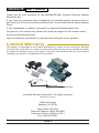
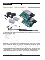
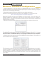
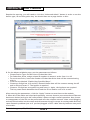
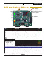
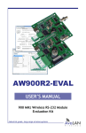
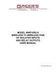
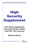
AW900mTR-EVAL
USER’S MANUAL
900 MHz Wireless Ethernet Module
Evaluation Kit
Industrial-grade, long-range wireless Ethernet systems
AvaLAN
W
I
R
E
L
E
S
S
AW900mTR User’s Manual
Thank you for your purchase of the AW900mTR-EVAL Wireless Ethernet Module
Evaluation Kit.
If you have any questions when configuring your AvaLAN system, the best place to
get answers is to visit www.avalanwireless.com. You will also find the latest updates
there.
If more assistance is needed, send email to [email protected].
To speak to a live technician, please call technical support at the number below
during normal business hours.
Note: Professional installation is required when using the sector antenna.
Limited Warranty
This product is warranted to the original purchaser for normal use for a period of 360 days
from the date of purchase. If a defect covered under this warranty occurs, AvaLAN will repair
or replace the defective part, at its option, at no cost. This warranty does not cover defects
resulting from misuse or modification of the product.
© AvaLAN Wireless Systems Inc. All rights reserved.
Revision 01.31.2014
125A Castle Drive
Madison, AL 35758
Sales: (866) 533-6216
Technical Support: (650) 384-0000
Customer Service: (650) 641-3011
Fax: (650) 249-3591
Technical support (650) 384-0000
PAGE 2
www.avalanwireless.com
User’s Manual AW900mTR
Operational summary
The AW900mTR Radio Module allows the user to create a long-range, wireless
Ethernet network with up to 16 subscriber units per access point. The configuration
may include any combination of AW900mTR, AW900xTR, AW900iTR and AW900xTP
radios. (Please note that older AvaLAN 900 MHz radios can exist on the same LAN
but cannot be used to form wireless links with the AW900mTR because link encryption protocols have changed.)
Configuring a wireless link with the AW900mTR requires the establishment of six
elements:
• Each radio must know whether it is to be an access point (AP) or subscriber
unit (SU).
• Each radio must have an IP address that is unique among all others on the
same network.
• The AP must know how many SUs are expecting communication with it.
• The AP and any given SU must agree on which radio frequency channel they
are using. This can be manually set or allowed to change automatically.
• The SU must be assigned a unique subscriber ID to specify which time division
slot it will use when communicating with the AP.
• The AP and any given SU must share a common 128-bit encryption key.
AW900mTR radios may be configured by two different methods. They may be connected to a computer that will run a web browser, setting parameters via their
built-in browser interfaces. They may also be programmed via the “easy key” method using the DIP switches and LEDs on the module.
The access point (AP) automatically scans for the best of the 12 available radio frequency channels, encrypts Ethernet data received from the network, and transmits
it wirelessly to the correct subscriber unit (SU). The AP is constantly monitoring the
radio link and can automatically change the channel if performance is degraded due
to interference. If two AP units are very close to one another, they may interfere
if operating on adjacent frequency channels. Place them at least 10 feet apart or
manually select non-adjacent channels for their operation. Also, the SU should be
placed at least 10 feet from the AP to avoid overloading the radio’s receiver.
Any 10/100 BaseT Ethernet client device (ECD) can be connected to an AW900mTR
subscriber unit. Each SU encrypts Ethernet traffic received from the attached ECD
and transmits the data wirelessly to its AP. Each SU can be plugged directly into an
ECD without adding drivers or loading software. Essentially, once the AP/SU pair is
configured and running it behaves like a continuous Ethernet cable.
Technical support (650) 384-0000
PAGE 3
www.avalanwireless.com
AW900mTR User’s Manual
Evaluation Kit Contents
The AW900mSPI-EVAL 900 MHz Wireless Ethernet Module Evaluation Kit contains two
each of the following items:
•
•
•
•
•
AW900mSPI Wireless Ethernet Modules
AW2-900 Omnidirectional Antennas
AW-P8 Antenna to Radio Connectors
AW-POE Power Over Ethernet Injectors
AW-12VPS 12 Volt Power Supplies
Additional quantities of any of these components may be purchased from AvaLAN
Wireless or our distributors.
To power up a radio module, connect the antenna via the pigtail cable provided.
Connect an Ethernet cable to the RJ-45 jack on the module. Power may be supplied to the module using the 12 VDC wall hanger power supply either through the
Ethernet cable using the POE or directly into the P5 jack on the module.
Provide some physical separation between two radio modules — at least five feet.
If their antennas are in close proximity, the module radio receivers will be overloaded, causing degredation in the bit error rate and slower link performance.
Technical support (650) 384-0000
PAGE 4
www.avalanwireless.com
User’s Manual AW900mTR
Physical Dimensions
Power: 5-48 VDC
Ethernet: 10/100T
Power: 9-48 VDC
Mounting Holes
23 mm
66 mm
70 mm
Antenna:
Reverse polarity
SMA
Mounting Holes
900 MHz Channels
Channel
0
1
2
3
4
5
6
7
8
9
10
11
12
Technical support (650) 384-0000
Center Frequency
Auto Mode
903.12500 MHz
905.20833 MHz
907.29167 MHz
909.37500 MHz
911.45833 MHz
913.54167 MHz
915.62500 MHz
917.70833 MHz
919.79167 MHz
921.87500 MHz
923.95833 MHz
926.04167 MHz
PAGE 5
www.avalanwireless.com
AW900mTR User’s Manual
Browser Interface Configuration
1. Digital configuration is done by means of the AW900mTR’s built in browser interface. It
should be powered on and connected at least temporarily to a network containing a computer
that can run a conventional web browser.
2. Download the AvaLAN IP Discovery Utility from our website and extract
ipfinder.exe from the zip archive, placing it on your desktop or in a convenient folder.
http://www.avalanwireless.com/ipfinder/ipfinder.zip
Note that this utility only runs on MS Windows, not linux or MAC. If you must use a nonWindows computer for configuration, make sure your subnet mask allows your computer to
see 192.168.17.17. Connect to that default IP address with your web browser, continuing the
setup procedure with step 6.
3. Run the IP Discovery Utility, ipfinder.exe and you should see a window similar to this:
The AW900mTR should appear in the list at the default IP address of 192.168.17.17. If it does
not, click “Search” to regenerate the list. If it still does not appear, you have a connection
issue and need to re-examine the cabling or you may have a firewall issue on your computer.
4. Double click the list item that refers to the AW900mTR being configured. You should see a
second window that is similar to this:
The information on the left is the current status of the radio, while the boxes on the right allow you to change it. It is important that the IP address of the AW900mTR is in the same subnet
as your computer. For example, if the subnet mask is 255.255.255.0 ( a class C network), the
first three number groups of the IP address must match. Choose your desired parameters and
click “Apply.”
Technical support (650) 384-0000
PAGE 6
www.avalanwireless.com
User’s Manual AW900mTR
5. Make note of the chosen IP address and password, then click “Go to Device Web Page.”
This will cause your default web browser to launch with the device IP address in the browser
address bar. Or you may launch the browser on your own and enter the web page address
manually: http://[the IP address you just set].
6. The browser page that loads first shows the current device information and QoS statistics
and provides a login at the upper right. Log in using the password you just specified (or “password” if you kept the default). If the login succeeds, you will see an admin page similar to
this:
7. The admin page has sections similar to the login page showing radio statistics and device
information plus it adds several new sections. The Device Settings section allows setting the
network information and choosing an RF frequency channel. The default is to allow the radio
to choose its own frequency based on minimizing interference. If you set a fixed channel,
make sure the AP and all SUs use the same one. References to DIPs on this and the next web
page refer to the DIP switches on the module that are used in the “easy key” method of configuration and may be ignored when using the browser method.
If you scroll down in the Admin browser page, you will come to three more sections:
• A graphical spectrum analyzer display that may help you to select radio channels that
avoid interference
• A section to be used if an update to the AW900mTR’s firmware is required
• An Advanced Links section with a dire warning about advanced users only.
Technical support (650) 384-0000
PAGE 7
www.avalanwireless.com
AW900mTR User’s Manual
Despite the warning, you will need to click the “Advanced Admin” button in order to set the
device type, ID and encryption key. You should then see a page similar to this:
8. On the Advanced Admin page, set the parameters as follows:
• Choose Device Type: Access Point or Subscriber Unit.
• For Subscriber Units, assign unique ID numbers in numeric order from 1 to 63.
• For an Access Point, enter the number of Subscriber Units that will be communicating
with it.
• Click the box labeled “Enable User Specified Keys.”
• Choose an 8-digit hex (0-9 and A-F) Network Name that will be common among the AP
and its SUs and enter it. The hyphen is required.
• Choose a 32-digit hex encryption key and enter it. Again, the hyphens are required.
This key must match between the AP and the SU so make a note of it as well.
After entering the parameters, click the “Apply” button to save them to the module.
9. When all of the radios are keyed and operating, connect them to your network and Ethernet
devices as desired and cycle the radio module’s power to begin normal operation. Now, browser management of the SUs can be performed over the wireless network. Note: avoid plugging
actively linked radios into the same switch because this will corrupt its routing table and may
cause network problems just as if you had plugged a CAT5 cable directly between two ports
of a switch.
Technical support (650) 384-0000
PAGE 8
www.avalanwireless.com
User’s Manual AW900mTR
LED and Switch Behavior
Reset Switch:
Press momentarily for soft
reset of processor. Hold for
10 seconds to reset module
to factory defaults.
LEDs
PWR
RX
TX
ETH
CH1
CH2
CH4
CH8
CH16
CH32
DIP Switches
1
2
3
4
5
6
7
8
LINK
QUALITY
LED
PWR
RX
TX
ETH
CH1
CH2
CH4
CH8
CH16
CH32
Function
Color
Red
Green
Green
Green
Green
Shows link quality
(more lit the better)
or indicates “key
exchange mode” if
blinking sequentially
Excellent link quality: no retransmissions
Very good link quality: few retransmissions
Good link quality: occasional retransmissions
Fair link quality: some retransmissions
Poor link quality: frequent retransmissions
No link quality: no link available
DIP Switch
Function (up is off, down is on)
Green
Green
Amber
Amber
Red
Red
1
2
3-8
Unit has power and has successfully booted
Radio reception is occuring
Radio transmission is occuring
Ethernet port is connected
By adding the numbers that are lit, you can determine
the current radio channel. Valid channels are 1 to 12,
CH16 and CH32 are not used. For the frequency of each
channel, see the table on page 5.
Set on for Access Point, off for Subscriber Unit
Test switch for tech support use. Leave off
All off: automatic frequency selection. To manually set the channel, set switches on in same pattern as the channel LEDs: Switch 3
is bit 1, switch 4 is bit 2, switch 5 is bit 4, etc.
Technical support (650) 384-0000
PAGE 9
www.avalanwireless.com
AW900mTR User’s Manual
“Easy Key” Configuration
In most cases, the browser interface is a better choice for configuring the modules.
But they also can be configured as a point-to-point bridge or a point-to-multipoint
group using the DIP switches. When this method is used, the module that will operate as the access point provides a unique network ID calculated from its MAC address and a unique random encryption key programmed into it during manufacture.
If you do configure a set of modules this way, be aware that they will all have the
factory default IP address of 192.168.1.17. If you later need access to a module via
the browser interface, use the IP Finder utility, select the individual unit and give
it a unique IP address.
Initial Setup:
1. Select the module that will operate as the access point (AP) and set its DIP
switch 1 on (down). Set DIP switch 1 off (up) on the module(s) that will operate as subscriber units (SUs).
2. Select matching frequency channels on all modules or select automatic channel selection by leaving DIP switches 3-8 off.
3. Power up the AP module. Its link quality LEDs will begin blinking sequentially,
showing that the module is hunting for an SU to exchange keys with.
4. Power up an SU module (its DIP switch 1 is off). This module’s link quality
LEDs will also begin blinking sequentially showing that it is hunting for an AP
to supply a network key.
5. Connect an Ethernet cable from the AP module to the SU module and the two
modules will automatically exchange keys. (Do not connect through a switch
or hub, but cable directly with a regular patch or crossover cable.)
• On the AP module, the link quality LEDs will still blink sequentially in key
exchange mode and the TX LED will light showing successful key exchange
• On the SU module, the link quality LEDs will no longer blink sequentially,
but one of the green link quality LEDs will slowly blink to indicate successful key exchange.
6. Repeat steps 4 and 5 for any other SU modules to be configured to the same
AP.
7. disconnect the Ethernet cable and cycle power on all modules for the new
keys to take effect. LED behavior should reflect normal RF operation once the
units are deployed.
Technical support (650) 384-0000
PAGE 10
www.avalanwireless.com
User’s Manual AW900mTR
To add a new SU to the AP, disconnect the AP from the network and power off.
Connect an Ethernet cable between the SU and AP. Power up the SU FIRST and then
the AP. The SU will receive the key. Disconnect the Ethernet cable and cycle power
on the SU to cause the new keys to take effect.
To re-key SUs to a new AP, proceed as in the inital setup, making sure to power up
the AP FIRST.
Technical specifications
Characteristic
Specification/Description
RF transmission rate
1.536 Mbps
Ethernet data rate
935 Kbps
Output Power
+21 dBm (4 Watts EIRP with 15 dBi antenna)
Receive Sensitivity
-97 dBm at 10-4 Bit Error Rate
Range
Up to 40 miles line-of-sight with 15 dBi antennas
RF channels/bandwidth
12 non-overlapping with 2.0833 MHz spacing and 1.75 MHz
bandwidth
Channel selection
Automatic or manual via DIP switches or browser interface
Adjacent band rejection
SAW receiver filter attenuates cellular and pager interference
Error correction
Sub-block error detection and retransmission
Encryption
128-bit AES, meets FIPS 197 Standard
Browser Management Tools
QoS statistics, network settings, spectrum analyzer
Status LEDs
Power, RF activity, Ethernet connect, channel, link quality
Connectors
RF: RPSMA Female, Ethernet: RJ-45, Power: P5, 2.1 mm ID
Power consumption
Transmit: 1.7 Watts, Receive: 0.8 Watts
Voltage
9-48 VDC, power over Ethernet pins 4,5 positive, 7,8
ground or via separate P5 jack
Power regulation
Switching regulator
Transmit current draw
175 ma at 9 VDC
140 ma at 12 VDC
35 ma at 48 VDC
Operating Temperature Range
-40 ºC to +80 ºC
Size
70 by 66 by 23 mm, 40 grams
Technical support (650) 384-0000
PAGE 11
www.avalanwireless.com
AW900mTR User’s Manual
FCC Certification
The AW900MTR OEM RF Module complies with Part 15 of the FCC rules and regulations. Compliance with labeling requirements, FCC notices and
antenna regulations is required.
Labeling Requirements
In order to inherit AvaLAN’s FCC Certification, compliance requires the following be stated on the device and within its operation manual:
FCC ID: R4N-AW900MR This device complies with Part 15 of the FCC Rules. Operation is subject to the following two conditions: (1) this device
may not cause harmful interference and (2) this device must accept any interference received, including interference that may cause undesired
operation.
Label Warning WARNING The Original Equipment Manufacturer (OEM) must ensure that FCC labeling requirements are met. This includes a clearly
visible label on the outside of the final product enclosure that displays the contents shown in the figure below.
Figure A.1. Required FCC Label for OEM products containing the AvaLAN AW900MR OEM RF Module
Contains FCC ID: R4N-AW900MR
The enclosed device complies with Part 15 of the FCC Rules. Operation is subject to the following two conditions:
(1) this device may not cause harmful interference and
(2) this device must accept any interference received, including interference that may cause undesired operation.
FCC Notices
Adherence to the following is required:
IMPORTANT: The AW900MR OEM RF Modules have been certified by the FCC for use with other products without any further certification (as per FCC
section 2.1091). Changes or modifications not expressly approved by AvaLAN could void the user’s authority to operate the equipment.
IMPORTANT: OEMs must test their final product to comply with unintentional radiators (FCC section 15.107 and 15.109) before declaring compliance of their final product to Part 15 of the FCC Rules.
IMPORTANT: The AW900MR OEM RF Modules have been certified for fixed base station and mobile applications. If modules will be used for portable
applications, the device must undergo SAR testing.
Note: This equipment has been tested and found to comply with the limits for a Class B digital device, pursuant to Part 15 of the FCC Rules.
These limits are designed to provide reasonable protection against harmful interference in a residential installation. This equipment generates,
uses and can radiate radio frequency energy and, if not installed and used in accordance with the instructions, may cause harmful interference to
radio communications. However, there is no guarantee that interference will not occur in a particular installation. If this equipment does cause
harmful interference to radio or television reception, which can be determined by turning the equipment off and on, the user is encouraged to try
to correct the interference by one or more of the following measures:
• Reorient or relocate the receiving antenna.
• Increase the separation between the equipment and receiving module.
• Connect the equipment into an outlet on a circuit different from that to which the receiving module is connected.
• Consult the dealer or an experienced radio/TV technician for help.
FCC-Approved Antennas (900 MHz)
Fixed Base Station and Mobile Applications
AvaLAN Modules are pre-FCC approved for use in fixed base station and mobile applications. When the antenna is mounted at least 23 cm (9.06”)
from nearby persons, the application is considered a mobile application.
Portable Applications and SAR Testing
When the antenna is mounted closer than 23 cm to nearby persons, then the application is considered “portable” and requires an additional test
be performed on the final product. This test is called the Specific Absorption Rate (SAR) testing and measures the emissions from the module and
how they affect the person.
RF Exposure
(This statement must be included as a CAUTION statement in OEM product manuals.)
WARNING: This equipment is approved only for mobile and base station transmitting devices. Antenna(s) used for this transmitter must be installed
to provide a separation distance of at least 23 cm from all persons and must not be co-located or operating in conjunction with any other antenna
or transmitter.
Antenna Warning
WARNING: This device has been tested with Reverse Polarity SMA connectors with the antennas listed in Table 1 below. When integrated into
OEM products, fixed antennas require installation preventing end-users from replacing them with non-approved antennas. Antennas not listed
in the table below must be tested to comply with FCC Section 15.203 (unique antenna connectors) and Section 15.247 (emissions). To fulfill FCC
Certification requirements:
1. Integrator must ensure required text [Figure 1] is clearly placed on the outside of the final product.
2. AW900MR Module may be used only with Approved Antennas that have been tested with this module.
Antenna Type
Dipole
Omni
Panel
Yagi
Sector*
Maximum Gain
≤ 2dBi
≤ 11dBi
≤ 12.5dBi
≤ 16dBi
≤ 18.5dBi
This Ethernet Module is approved for use only with specific antenna, cable, and output power configurations that have been tested and approved
for use. Modifications to the module, the antenna system, or to the power output that have not been explicitly specified by the manufacturer are
not permitted and may render the radio non-compliant with applicable regulatory authorities. The radio equipment described in this manual emits
radio frequency energy. Professional installation is required. The antenna(s) for this transmitter must not be collocated or operated in conjunction
with any other antenna ortransmitter. When using the sector antenna to ensure cable attentuation between the radio module and antenna is
atleast 1.4dB to maintain compliance to FCC/IC EIRP limits. The recommended cable length when using the sector antenna is 10ft of LMR200 cable.
Technical support (650) 384-0000
PAGE 12
www.avalanwireless.com
User’s Manual AW900mTR
IC (Industry Canada) Certification
Labeling requirements for Industry Canada are similar to those of the FCC. A clearly visible label on the outside of the final product enclosure
must display the following text:
Contains Model AW900MR Radio, IC: 5303A-AW900MR
Integrator is responsible for its product to comply with IC ICES-003 & FCC Part 15, Sub. B - Unintentional Radiators. ICES-003 is the same as FCC
Part 15 Sub. B and Industry Canada accepts FCC test report or CISPR 22 test report for compliance with ICES-003.
Under Industry Canada regulations, this radio transmitter may only operate using an antenna of a type and maximum (or lesser) gain approved for
the transmitter by Industry Canada. To reduce potential radio interference to other users, the antenna type and its gain should be so chosen that
the equivalent isotropically radiated power (e.i.r.p.) is not more than that necessary for successful communication.
Conformément à la réglementation d’Industrie Canada, le présent émetteur radio peut fonctionner avec une antenne d’un type et d’un gain maximal (ou inférieur) approuvé pour l’émetteur par Industrie Canada. Dans le but de réduire les risques de brouillage radioélectrique à l’intention
des autres utilisateurs, il faut choisir le type d’antenne et son gain de sorte que la puissance isotrope rayonnée équivalente (p.i.r.e.) ne dépasse
pas l’intensité nécessaire à l’établissement d’une communication satisfaisante.
This radio transmitter has been approved by Industry Canada to operate with the antenna types listed below with the maximum permissible gain
and required antenna impedance for each antenna type indicated. Antenna types not included in this list, having a gain greater than the maximum
gain indicated for that type, are strictly prohibited for use with this device.
Le présent émetteur radio (identifier le dispositif par son numéro de certification ou son numéro de modèle s’il fait partie du matériel de catégorie
I) a été approuvé par Industrie Canada pour fonctionner avec les types d’antenne énumérés ci-dessous et ayant un gain admissible maximal et
l’impédance requise pour chaque type d’antenne. Les types d’antenne non inclus dans cette liste, ou dont le gain est supérieur au gain maximal
indiqué, sont strictement interdits pour l’exploitation de l’émetteur.
Antenna Type
Dipole
Omni
Panel
Yagi
Sector*
Maximum Gain
≤ 2dBi
≤ 11dBi
≤ 12.5dBi
≤ 16dBi
≤ 18.5dBi
The antenna(s) for this transmitter must not be collocated or operated in conjunction with any other antenna or transmitter. When using the sector
antenna to ensure cable attentuation between the radio module and antenna is atleast 1.4dB to maintain compliance to FCC/IC EIRP limits. The
recommended cable length when using the sector antenna is 10ft of LMR200 cable.
This device complies with Industry Canada licence-exempt RSS standard(s). Operation is subject to the following two conditions: (1) this device
may not cause interference, and (2) this device must accept any interference, including interference that may cause undesired operation of the
device.
Le présent appareil est conforme aux CNR d’Industrie Canada applicables aux appareils radio exempts de licence. L’exploitation est autorisée
aux deux conditions suivantes : (1) l’appareil ne doit pas produire de brouillage, et (2) l’utilisateur de l’appareil doit accepter tout brouillage
radioélectrique subi, même si le brouillage est susceptible d’en compromettre le fonctionnement.
Technical support (650) 384-0000
PAGE 13
www.avalanwireless.com