1
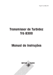
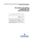
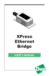
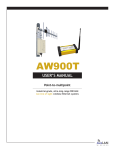
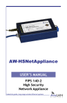
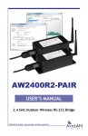
AW900mSPI
and
AW900mSPI-EVAL
USER’S MANUAL
900 MHz Digital Radio Transceiver Module
and Evaluation Kit
With SPI or UART Data Interface
Industrial-grade, long-range wireless Ethernet systems
AvaLAN
W
I
R
E
L
E
S
S
AW900mSPI User’s Manual
Thank you for your purchase of the AW900mSPI 900 MHz Digital Radio Transceiver
Module with SPI or UART Data Interface.
The Module itself may be ordered in quantities of ten as the AW900mSPI-10.
The AW900mSPI-EVAL Evaluation Kit includes:
• (2) Evaluation controller PC Boards with AW900mSPI Radio Modules mounted
on them
• (2) 120 VAC to 12 VDC power adapters and (1) Battery Pack
• (2) USB Cables
• (2) Omni-directional antennas with 8” RPSMA to RPTNC RF Cables
Firmware and software described in this manual may be downloaded from
www.avalanwireless.com/downloads.htm. (You can also find a pdf of the latest
version of this manual.)
If you have any questions when configuring your AvaLAN system, the best place to
get answers is to visit www.avalanwireless.com. If more assistance is needed, send
email to [email protected]. To speak to a live technician, please call
technical support at the number below during normal business hours.
© 2011 by AvaLAN Wireless Systems Inc. All rights reserved.
Revision 01.20.2011
125A Castle Drive
Madison, AL 35758
Sales: (866) 533-6216
Technical Support: (650) 384-0000
Customer Service: (650) 641-3011
Fax: (650) 249-3591
Technical support (650) 384-0000
PAGE 2
www.avalanwireless.com
User’s Manual AW900mSPI
Table of Contents
Features and Specifications . . . . . . . . . . . . . . . . .
4
Technical Summary . . . . . . . . . . . . . . . . . . . . . . .
5
Module Physical Interface . . . . . . . . . . . . . . . . . .
6
Module SPI Interfaces . . . . . . . . . . . . . . . . . . . . .
6
Module UART Interface . . . . . . . . . . . . . . . . . . . . . 10
Module Command Set . . . . . . . . . . . . . . . . . . . . . 12
Programming Examples . . . . . . . . . . . . . . . . . . . . 26
Implementation Block Diagrams . . . . . . . . . . . . . . 29
Evaluation Board Physical Interface . . . . . . . . . . . 30
Technical Evaluation Process . . . . . . . . . . . . . . . . . 31
Next Steps . . . . . . . . . . . . . . . . . . . . . . . . . . . 38
FCC and IC Certification . . . . . . . . . . . . . . . . . . . . . 39
Technical support (650) 384-0000
PAGE 3
www.avalanwireless.com
AW900mSPI User’s Manual
Features and Specifications
• 1.54 Mbps DSSS Radio with High Speed SPI and UART Data Interfaces
• FCC/IC Certified modular approval
• 128 Bit AES Encryption – FIPS 197 NIST Certified
• 148 dB link budget at 900 Mhz enables exceptional range
• 4 Watts EIRP with 15 dBi antennae (+21 dB conducted)
• -112 dB receiver sensitivity with 15 dBi antennae (-98dB at port)
• TDMA MAC supports up to 63 concurrent subscribers
• Low power consumption: 0.75 Watts in transmit, 0.5 Watts in receive,
100 µW in standby
• Wide Temperature range: -40° to +85° C
• Narrow occupied bandwidth allows 12 channels at 900 Mhz
• Small form factor allows easy integration: 47.5 x 51 x 7 mm, 10 grams
• Frequency Channels: 2.0833 MHz spacing and 1.75 MHz occupied bandwidth
Channel
Center Frequency - MHz
0
Automatic Selection
1
903.1250
2
905.2083
3
907.2917
4
909.3750
5
911.4583
6
913.5417
7
915.6250
8
917.7083
9
919.7917
10
921.8750
11
923.9583
12
926.0417
Technical support (650) 384-0000
PAGE 4
www.avalanwireless.com
User’s Manual AW900mSPI
Technical Summary
The AW900mSPI modules from AvaLAN Wireless have an on-board Baseband processor, the XC1220 from AvaLAN Wireless. The XC1220 handles all RF timing, data buffering, AES encryption, RF data transfers and statistics gathering. The XC1220 must
be connected to a host microcontroller via a Serial Peripheral Interface (SPI) or
a Universal Asynchronous Receiver/Transmitter (UART). AvaLAN’s packaged radios,
such as the AW900XTR, include a host microcontroller that provides an Ethernet
interface. The purpose of this RF-only module is to allow you to create other applications and interfaces with your own electronics.
The host microcontroller is responsible for configuring the keys that the XC1220
uses for RF communication/encryption, as well as transferring data to and from the
XC1220. The XC1220 features an 8kB transmit FIFO and a 5kB receive FIFO. The RF
communication topology that the modules use is a point to multipoint star topology.
There is one RF master Access Point (AP) and up to 63 RF slave Subscriber Units (SU).
Data from the AP can be sent to one specific SU or broadcast to all SUs. Broadcast
data has no retransmissions and is not guaranteed to reach all SUs. Data from an SU
is always sent to the AP with retransmissions.
Data is divided up into blocks for RF transmission. This division of the data allows
for better interference immunity and re-transmission performance.
The digital interface to the AW900mSPI may be SPI or UART, depending upon which
firmware is running in the XC1220.
Serial Peripheral Interface (SPI) is a full duplex synchronous serial interface. SPI is
a master-slave interface, with the master providing the synchronous clock.
Universal Asynchronous Receiver/Transmitter (UART) is an asynchronous serial
interface that allows data to be transmitted without a clock signal, but the sender
and receiver of the data must agree in advance on the timing parameters and special bits are added to each data byte to synchronize the sending and receiving units.
Selecting SPI or UART:
The choice of interface is up to the user and governed by the user's application and
the nature of the host microcontroller. UART is more common, being closely related
to RS-232. It is also places fewer demands on the host microcontroller. The UART
interface is limited to 115,200 bits per second, while SPI may be run as high as 7
megabits per second. Whether the AW900mSPI uses SPI or UART is a choice that is
controlled at boot up. By connecting a 10K resistor from Pin 8 (Error Flag) to Vcc
(pull up), the AW900mSPI will boot up in UART mode. If the resistor is connected
instead to ground (pull down), it will boot up in SPI mode.
Technical support (650) 384-0000
PAGE 5
www.avalanwireless.com
AW900mSPI User’s Manual
Module Physical Interface
RF Antenna
RPSMA
RF Section
AvaLAN
XC1220 Chip
Pin 1
Pin 17
Module SPI Interfaces
Serial Peripheral Interface (SPI) is a full duplex synchronus serial interface that allows data to be shifted in and out of the AvaLAN Baseband Processor (XC1220) 8 bits
at a time, most significant bit first.
Each SPI requires 4 pins to be physically connected:
• SCK – Serial bit shift clock (provided by master SPI)
• MISO – Master In Slave Out
• MOSI – Master Out Slave In
• CS – Active low Chip Select
There are two SPI interfaces on the AW900mSPI. The first is a master SPI (SPI0),
operating LEDs and DIP switches. SPI0’s connections are pins 3-6. The second is a
slave SPI (SPI1) for management of the radio link, statistics, firmware upgrading,
and data transfers. SPI1’s connections are on pins 12-15.
Technical support (650) 384-0000
PAGE 6
www.avalanwireless.com
User’s Manual AW900mSPI
Here are the Signal definitions for the AW900SPI in SPI mode:
Pin Number
Name
Description
1
Vcc
3.3 vdc for XC1220
2
/CS_LED
Chip select for LEDs and DIP switches (active low)C
3
/CS_PD
Chip select for external programming devicehip s
4
SCK0
Serial clock for LEDs and DIP switches
5
MISO0
Data in for LEDs and DIP switches
6
MOSI0
Data out for LEDs and DIP switches
7
GND
XC1220 Ground
8
Error Flag
1=last command not understood. Clear with /CS_BB
9
Data Ready
1=data packet available, 0=no data
10
FIFO Full Flag
1=FIFO full, don’t send any more data, 0=FIFO is empty
11
Connected Flag
1=RF connection present, 0=RF searching/standby
12
/CS_BB
Chip select for XC1220
13
SCK1
Serial clock for XC1220
14
MOSI1
Data out for XC1220
15
MISO1
Data in for XC1220
16
RFVcc
3.3 vdc for RF section
17
RFGND
RF section ground
SPI0 uses mode (0,0) for clock phase and polarity. This means that the SCK0 line
idles low and data is setup on the falling edge of the clock and latched on the rising
edge. SPI1 uses mode (1,1), meaning that SCK1, MISO1 and MOSI1 are all idle high.
Data is still set up on the falling edge and latched on the rising edge of the clock.
The clock rate for the SPI0 interface is 1.5625 MHz. The maximum clock rate for
the SPI1 interface is 7 MHz and the minimum clock rate is 530 kHz (minimum clock
period of 143 ns and a maximum of 1887 ns).
CS
MISO
b7
b6
b5
b4
b3
b2
b1
b0
MOSI
b7
b6
b5
b4
b3
b2
b1
b0
SCK
Technical support (650) 384-0000
PAGE 7
www.avalanwireless.com
AW900mSPI User’s Manual
SPI0 - LEDs and DIP Switches
SPI0 is a master mode SPI that sends out 4 bytes per transaction. The first two bytes
are alignment bytes and the last two contain the LED data on MOSI0, and the DIP
switch data on MISO0.
The first alignment byte is 0x55, and the second is 0xAA. These two bytes are used
to determine the start of the transaction (0x55) and the start of the data (0xAA).
LEDs:
/CS_LED
MISO0
XX
XX
Byte3
Byte4
MOSI0
0x55
0xAA
Byte3
Byte4
SCK0
A bit that is set in either of these bytes indicates that the corresponding LED should
be on.
Byte3
b7
b6
b5
b4
b3
b2
b1
b0
PWR
RX_ACT
LCH5
LCH4
LCH3
LCH2
LCH1
LCH0
PWR: Turns on when the firmware is running. In troubleshoot mode PWR changes
states on the AP every time a search for more SUs takes place. On a SU PWR changes state every time the SU responds to a search for more SUs.
RX_ACT: Indicates when data traffic has been received by the RF. RX_ACT will be
set for 32ms when data has been successfully received.
LCH5..0: Indicates what RF channel is currently in use. In troubleshoot mode these
bits indicate what the unit’s device ID is.
Byte4
b7
b6
b5
b4
b3
b2
b1
b0
TX_ACT
-
RFQ5
RFQ4
RFQ3
RFQ2
RFQ1
RFQ0
TX_ACT: Indicates when data traffic is queued up for transmission across the RF. Technical support (650) 384-0000
PAGE 8
www.avalanwireless.com
User’s Manual AW900mSPI
TX_ACT will be set for 32ms when data is queued up for transmission.
RFQ5..0: Indicates the quality of the RF link. The lowest quality is only b0 set, the
highest quality is reached when b5 is set.
DIPs:
A bit that is set in this byte indicates that the corresponding DIP switch is on.
Byte3
b7
b6
b5
b4
b3
b2
b1
b0
DCH5
DCH4
DCH3
DCH2
DCH1
DCH0
MODE
-
DCH5..0: Used to set the radio into manual channel mode and use the channel indicated. If DCH5..0 are all clear then the radio will be in automatic mode.
MODE: When set the unit is in troubleshooting mode, when clear the unit is in
normal operation.
SPI1 – Command Interface
SPI1 is a slave mode SPI, meaning SCK is supplied by an external source. This SPI
is used to configure the module, read status information, issue firmware upgrades
and transfer data.
The first byte on the MOSI line after the /CS_BB line goes low is the Command Byte. This byte tells the XC1220 what command is to be executed.
Command Byte:
b7
b6
b5
b4
b3
b2
b1
b0
get/set
-
-
-
CMD3
CMD2
CMD1
CMD0
get/set: When set this bit indicates that information will be sent to the XC1220 on
MOSI1 and MISO1 will be high impedance. When clear a get transaction will take
place and information will be sent from the XC1220 on MISO1.
After the command byte is issued the master microcontroller must delay for at least
4 µs to allow the XC1220 enough time to prepare for the transaction.
When a transaction is complete and the /CS_BB line is high, the master microcontroller must delay for at least 6 µs to allow the XC1220 to finish processing the
transaction.
CMD3..1: These bits are used to tell the XC1220 what command is to be executed.
Technical support (650) 384-0000
PAGE 9
www.avalanwireless.com
AW900mSPI User’s Manual
Module UART Interface
Here are the Signal definitions for the AW900SPI in UART mode:
Pin Number
Name
Description
1
Vcc
3.3 vdc for XC1220
2
/CS_LED
Chip select for external programming device
3
/CS_PD
Chip select for LEDs and DIP switches (active low)Chip s
4
SCK0
Serial clock for LEDs and DIP switches
5
MISO0
Data in for LEDs and DIP switches
6
MOSI0
Data out for LEDs and DIP switches
7
GND
XC1220 Ground
8
NC
Not Used
9
NC
Not Used
10
NC
Not Used
11
NC
Not Used
12
NC
Not Used
13
NC
Not Used
14
MOSI1
UART TX
15
MISO1
UART RX
16
RFVcc
3.3 vdc for RF section
17
RFGND
RF section ground
In UART mode, the AW900mSPI's command interface is moved to SPI0. The LEDs and
DIP switches may still be employed, but the primary purpose of this SPI port has
shifted. SPI1 now becomes an asynchronous UART with TX on pin 14 and RX on pin
15 and is used for data that is transmitted and received via the RF.
At the risk of belaboring what is obvious and familiar to most engineers because
of the long history of RS-232, the UART signals consist of a set of bits sent with a
pre-defined clock rate. The sender must agree on what the rate is, and because the
sender’s clock and receiver’s clock may not exactly agree, synchronization information is sent with each byte of data:
t0
t1
t2
t3
t4
t5
t6
t7
t8
t9
t10
Mark
Space
Start
Bit
D0
D1
D2
T
D3
D4
D5
D6
D7
Stop
Bit
Baud Rate = 1/T
Single byte transmission (8 bits + Start + Stop)
The Stop Bit can actually be any duration and provides the variable delay that
allows synchronization between sender and receiver. Sometimes, the Stop Bit is
Technical support (650) 384-0000
PAGE 10
www.avalanwireless.com
User’s Manual AW900mSPI
specified to be at least two intervals. Also, sometimes a Parity Bit is sent between
D7 and the Stop Bit, but this is rarely done anymore.
UART Mode LEDs and DIPs:
With the UART firmware running, the LED definitions are the same as for SPI mode
and provide diagnostic information if desired.
The DIP switch definitions are slightly different:
b7
Byte3
b6
b5
b4
b3
b2
b1
b0
DCH3
DCH2
DCH1
DCH0
MODE
-
Byte4
TEST
MODE: 1 = Access Point, 0 = Subscriber Unit
DCH3 to DCH0: 4-bit binary code for the RF channel selected. (All zeros means use
automatic channel switching.)
TEST: 1 = Continuous traffic for site survey testing, 0 = normal operation.
Technical support (650) 384-0000
PAGE 11
www.avalanwireless.com
AW900mSPI User’s Manual
Module Command Set
The Command Sets for SPI and UART modes are somewhat different:
SPI Command Set
Command Byte - HEX
Command
0x01
getStatus
0x02
getNetworkKey
0x03
getPrivateKey
0x04
getDeviceID
0x05
getStats
0x06
getVersion
0x07
not valid
0x08
getNumberofConnectedSUs
0x09
getRSSIreadings
0x0A
getDATAPacket
0x81
setStatus
0x82
setPublicKey
0x83
setPrivateKey
0x84
setDeviceID
0x85
setReset
0x86
not valid
0x87
not valid
0x88
not valid
0x89
not valid
0x8A
setDATAPacket
0x8B
setFirmwareStart
0x8C
setFirmwareEnd
Technical support (650) 384-0000
PAGE 12
www.avalanwireless.com
User’s Manual AW900mSPI
UART Command Set
Command Byte - HEX
Command
0x00
getStatus
0x01
getNetworkKey
0x02
getPrivateKey
0x03
getDeviceID
0x04
getStats
0x05
getVersion
0x06
getConfig
0x07
getNumberofConnectedSUs
0x08
getRSSIreadings
0x09
not valid
0x80
setStatus
0x81
setPublicKey
0x82
setPrivateKey
0x83
setDeviceID
0x84
setReset
0x85
not valid
0x86
not valid
0x87
not valid
0x89
not valid
0x8B
setDATAPacket
In the Command Descriptions that follow, the command codes for each mode are
shown in the byte tables.
Technical support (650) 384-0000
PAGE 13
www.avalanwireless.com
AW900mSPI User’s Manual
Status Command
The getStatus command is used to find out the current status of the module.
getStatus
Byte 1
SPI Mode:
UART Mode:
0x01
0x00
b7
b6
b5
b4
b3
b2
b1
b0
RFState
Radio
-
-
CH3
CH2
CH1
CH0
RFState: When set this bit indicates that the RF is currently connected.
Radio: Indicates what mode the radio is in, when set it is in active mode. When
clear the RF is in standby mode.
CH3..0: Indicates what channel the RF is currently using.
The setStatus command is used to place the module in standby mode/normal operation and to set the RF into manual channel mode by assigning a specific channel.
setStatus
Byte 1
SPI Mode:
UART Mode:
0x81
0x80
b7
b6
b5
b4
b3
b2
b1
b0
-
Radio
-
-
CH3
CH2
CH1
CH0
Radio: Setting this bit places the radio in active mode, clearing it places it in
standby mode.
CH3..0: When these bits are cleared the radio is in automatic channel mode. When
any of these bits are set the radio will be in manual channel mode and use the channel indicated by these bits if it is valid.
Channel
1
2
3
4
5
6
7
8
9
10
11
12
CH3
0
0
0
0
0
0
0
1
1
1
1
1
CH2
0
0
0
1
1
1
1
0
0
0
0
1
Technical support (650) 384-0000
CH1
0
1
1
0
0
1
1
0
0
1
1
0
CH0
1
0
1
0
1
0
1
0
1
0
1
0
PAGE 14
Frequency - MHz
903.1250
905.2083
907.2917
909.3750
911.4583
913.5417
915.6250
917.7083
919.7917
921.8750
923.9583
926.0417
www.avalanwireless.com
User’s Manual AW900mSPI
Network Key Command
The Network Key is A 32-bit number used for Network Identification. AvaLAN mseries devices with different Network Keys will not be able to communicate with
each other. The Network Key can be changed without resetting the device.
The getNetworkKey command will read back the last 32-bit key issued to the
device.
The setNetworkKey command stores a new 32-bit key to be used for RF
communications.
getNetworkKey
SPI Mode:
0x02
UART Mode:
0x01
setNetworkKey
SPI Mode:
0x82
UART Mode:
0x81
Byte 1
b7
PK7
b6
PK6
b5
PK5
b4
PK4
b3
PK3
b2
PK2
b1
PK1
b0
PK0
Byte 2
PK15
PK14
PK13
PK12
PK11
PK10
PK9
PK8
Byte 3
PK23
PK22
PK21
PK20
PK19
PK18
PK17
PK16
Byte 4
PK31
PK30
PK29
PK28
PK27
PK26
PK25
PK24
Private Key Command
The Private Key is the 128-bit key used in the AES encryption of data transmitted
over the RF. This key must be set once at start up and cannot be changed without
resetting the device. If two or more radios have the same Public Key but different
Private Keys, they will connect with each other. However, the received data will be
completely scrambled.
The getPrivateKey command reads back the private key issued at startup.
The setPrivateKey command stores the private key to be used for the AES encryption. This command should be issued only once at start up. If issued again with a
different key, data corruption will occur.
getPrivateKey
SPI Mode:
0x03
UART Mode:
0x02
setPrivateKey
SPI Mode:
0x83
UART Mode:
0x82
Byte 1
b7
SK7
b6
SK6
b5
SK5
b4
SK4
b3
SK3
b2
SK2
b1
SK1
b0
SK0
Byte 2
SK15
SK14
SK13
SK12
SK11
SK10
SK9
SK8
Technical support (650) 384-0000
PAGE 15
www.avalanwireless.com
AW900mSPI User’s Manual
Byte 3
SK23
SK22
SK21
SK20
SK19
SK18
SK17
SK16
Byte 4
SK31
SK30
SK29
SK28
SK27
SK26
SK25
SK24
Byte 5
SK39
SK38
SK37
SK36
SK35
SK34
SK33
SK32
Byte 6
SK47
SK46
SK45
SK44
SK43
SK42
SK41
SK40
Byte 7
SK55
SK54
SK53
SK52
SK51
SK50
SK49
SK48
Byte 8
SK63
SK62
SK61
SK60
SK59
SK58
SK57
SK56
Byte 9
SK71
SK70
SK69
SK68
SK67
SK66
SK65
SK64
Byte 10
SK79
SK78
SK77
SK76
SK75
SK74
SK73
SK72
Byte 11
SK87
SK86
SK85
SK84
SK83
SK82
SK81
SK80
Byte 12
SK95
SK94
SK93
SK92
SK91
SK90
SK89
SK88
Byte 13
SK103
SK102
SK101
SK100
SK99
SK98
SK97
SK96
Byte 14
SK111
SK110
SK109
SK108
SK107
SK106
SK105
SK104
Byte 15
SK119
SK118
SK117
SK116
SK115
SK114
SK113
SK112
Byte 16
SK127
SK126
SK125
SK124
SK123
SK122
SK121
SK120
Device ID Command
The Device ID command has two uses depending on whether the device is configured as an access point (AP) or subscriber unit (SU.) In either case, the Device ID is
a 6-bit number, allowing a maximum ID of 63. The Device ID must be issued at start
up and must not be changed without resetting the device.
For the AP the Device ID is the maximum SU ID that is allowed to connect to the RF
network.
For the SU the Device ID is the individual ID number assigned to the device. This ID
number is used as an address during data transfers.
The getDeviceID command reads back the configured ID.
The setDeviceID command configures the device to be either an AP or an SU and
what ID to use.
getDeviceID
setDeviceID
Byte 1
b7
D1
SPI Mode:
0x04
SPI Mode:
0x84
b6
D0
Technical support (650) 384-0000
b5
MID5
b4
MID4
PAGE 16
b3
MID3
UART Mode:
0x03
UART Mode:
0x83
b2
MID2
b1
MID1
b0
MID0
www.avalanwireless.com
User’s Manual AW900mSPI
D1, D0: These bits report or configure whether the device is an AP or an SU:
D1
D0 Mode
0
0
Not Configured
0
1
AP
1
0
AP
1
1
SU
MID5..0: These bits read back or set the configured ID. For an AP this is the maximum ID number that is allowed to join the RF network. For an SU it is the number
to use to join the RF network.
Stats Command
The getStats command is used to gather all the statistics that the XC1220 is collecting about the RF link. The statistics are, total number of packets transferred, total
number of packets that failed to make it across the RF, total number of packets that
successfully made it across the RF, total number of broadcast packets, total number
of unicast packets, average transmitted packet size in the last 32 packets, average
received packet size in the last 32 packets, and percentage block error rate.
The statistics can be read from the XC1220 at any time during normal operation.
getStats
SPI Mode:
UART Mode:
0x05
0x04
Byte 1
b7
TP23
b6
TP22
b5
TP21
b4
TP20
b3
TP19
b2
TP18
b1
TP17
b0
TP16
Byte 2
TP31
TP30
TP29
TP28
TP27
TP26
TP25
TP24
Byte 3
TP7
TP6
TP5
TP4
TP3
TP2
TP1
TP0
Byte 4
TP15
TP14
TP13
TP12
TP11
TP10
TP9
TP8
Byte 5
FP23
FP22
FP21
FP20
FP19
FP18
FP17
FP16
Byte 6
FP31
FP30
FP29
FP28
FP27
FP26
FP25
FP24
Byte 7
FP7
FP6
FP5
FP4
FP3
FP2
FP1
FP0
Byte 8
FP15
FP14
FP13
FP12
FP11
FP10
FP9
FP8
Byte 9
PP23
PP22
PP21
PP20
PP19
PP18
PP17
PP16
Byte 10
PP31
PP30
PP29
PP28
PP27
PP26
PP25
PP24
Technical support (650) 384-0000
PAGE 17
www.avalanwireless.com
AW900mSPI User’s Manual
Byte 11
PP7
PP6
PP5
PP4
PP3
PP2
PP1
PP0
Byte 12
PP15
PP14
PP13
PP12
PP11
PP10
PP9
PP8
Byte 13
BC23
BC22
BC21
BC20
BC19
BC18
BC17
BC16
Byte 14
BC31
BC30
BC29
BC28
BC27
BC26
BC25
BC24
Byte 15
BC7
BC6
BC5
BC4
BC3
BC2
BC1
BC0
Byte 16
BC15
BC14
BC13
BC12
BC11
BC10
BC9
BC8
Byte 17
UC23
UC22
UC21
UC20
UC19
UC18
UC17
UC16
Byte 18
UC31
UC30
UC29
UC28
UC27
UC26
UC25
UC24
Byte 19
UC7
UC6
UC5
UC4
UC3
UC2
UC1
UC0
Byte 20
UC15
UC14
UC13
UC12
UC11
UC10
UC9
UC8
Byte 21
ATX7
ATX6
ATX5
ATX4
ATX3
ATX2
ATX1
ATX0
Byte 22
ATX15
ATX14
ATX13
ATX12
ATX11
ATX10
ATX9
ATX8
Byte 23
ARX7
ARX6
ARX5
ARX4
ARX3
ARX2
ARX1
ARX0
Byte 24
ARX15
ARX14
ARX13
ARX12
ARX11
ARX10
ARX9
ARX8
Byte 25
BER7
BER6
BER5
BER4
BER3
BER2
BER1
BER0
Byte 26
BER15
BER14
BER13
BER12
BER11
BER10
BER9
BER8
Bytes 1 to 4 are the 32-bit total number of packets sent and received (TP0 to TP31).
Bytes 5 to 8 are the 32-bit total number of failed packets sent and received (FP0
to FP31).
Bytes 9 to 12 are the 32-bit total number of passed packets sent and received (PP0
to PP31).
Bytes 13 to 16 are the 32-bit total number of broadcast packets sent and received
(BC0 to BC31).
Bytes 17 to 20 are the 32-bit total number of unicast packets sent and received
(UC0 to UC31).
Bytes 21 and 22 are the 16-bit average transmitted packet size over the last 32
packets (ATX0 to ATX15).
Bytes 23 and 24 are the 16-bit average received packet size over the last 32 packets
(ARX0 to ARX15).
Bytes 25 and 26 are the 16-bit percentage block error rate. BER15..8 is the integer
Technical support (650) 384-0000
PAGE 18
www.avalanwireless.com
User’s Manual AW900mSPI
part and ranges from 0 to 100. BER7..0 is the 2-digit fractional part and ranges from
0 to 99. The block error rate is calculated over the last 1000 data blocks.
Version Command
The getVersion command is used to determine the firmware version running in the
XC1220.
getVersion
SPI Mode:
UART Mode:
0x06
0x05
Byte 1
b7
RFV3
b6
RFV2
b5
RFV1
b4
RFV0
b3
PV3
b2
PV2
b1
PV1
b0
PV0
Byte 2
RV7
RV6
RV5
RV4
RV3
RV2
RV1
RV0
Byte 3
RV15
RV14
RV13
RV12
RV11
RV10
RV9
RV8
PV0 to PV3 is the 4-bit product version number.
RFV0 to RFV3 is the 4-bit radio version number.
RV0 to RV15 is the 16-bit firmware release version number.
Connected SUs Command
The getNumberofConnectedSUs command is used on the AP only, if issued on the
SU it will return all zeros. It returns the current number of SUs that are connected
to the RF network (5-bit number, CC0 to CC4).
getNumberofConnectedSUs
Byte 1
b7
x
b6
x
SPI Mode:
b5
x
b4
CC4
0x08
b3
CC3
UART Mode:
b2
CC2
b1
CC1
0x07
b0
CC0
RSSI Command
The getRSSIReadings command is used to determine if possible interference exists in the RF environment. The AW900mSPI can perform a spectrum analysis scan,
stepping through the frequency band and measuring the peak and average power
received at each frequency. Note: When two or more radios are actively linked, the
AP will tell the SUs to cease transmitting when it goes into spectrum scan mode.
However, when an SU scans, it will likely see a peak transmission from another
radio.
The host microcontroller sends the resolution settings to the XC1220, then gets
Technical support (650) 384-0000
PAGE 19
www.avalanwireless.com
AW900mSPI User’s Manual
channel information back from the XC1220. The host microcontroller must delay
while the XC1220 completes the scan before reading any data. In SPI mode, the
XC1220 will use the Data Ready line (pin 9) to indicate when the scan is complete
and the data is available. In UART mode, the host microcontroller needs to issue the
command and wait for data to be returned.
getRSSIReadings
Byte 1
b7
SS3
SPI Mode:
b6
SS2
b5
SS1
UART Mode:
0x09
b4
SS0
b3
EXP3
b2
EXP2
b1
EXP1
0x08
b0
EXP0
Note that this command is an exception to the general rule that “get” commands
receive data and “set” commands send it. This command must be followed by sending one byte of configuration information and then reading back a variable number
of data bytes.
SS0 to SS3 is the frequency step size (valid numbers are 1, 2, 4, 8).
EXP0 to EXP3 is the base-2 exponent of the number of samples to collect and average together at each frequency step.
EXP3...0
Number of Samples
0
1
1
2
2
4
3
8
4
16
5
32
6
64
7
128
8
256
The number of samples and frequency step size affects the amount of time it takes
to scan the band. A step size of 1 and exponent of 8 takes approximately 2 seconds
to scan the band. A step size of 8 and exponent of 32 takes approximately 300ms
to scan.
Although a higher step size and lower exponent scan much faster, a complete picture of the band may not be formed. Devices that only transmit for a very short
period of time may be missed with a fast scan.
Technical support (650) 384-0000
PAGE 20
www.avalanwireless.com
User’s Manual AW900mSPI
Byte 2
b7
BASE7
b6
BASE6
b5
BASE5
b4
BASE4
b3
BASE3
b2
BASE2
b1
BASE1
b0
BASE0
Byte 3
BASE15
BASE14 BASE13 BASE12 BASE11 BASE10
BASE9
BASE8
BASE is a 16-bit integer constant that provides the index offset for establishing the
RF frequency. For the AW900mSPI, this value is 1688.
Byte 4
b7
NUM7
b6
NUM6
b5
NUM5
b4
NUM4
b3
NUM3
b2
NUM2
b1
NUM1
b0
NUM0
Byte 5
DEN7
DEN6
DEN5
DEN4
DEN3
DEN2
DEN1
DEN0
NUM and DEN are 8-bit integer constants used to calculate the frequency value corresponding to each index step. For the AW900mSPI, NUM = 25 and DEN = 48.
Frequency in MHz = (Index + BASE) * NUM / DEN
Where Index is an integer value starting with zero. For example, the lowest transmit channel for the AW900mSPI corresponds to an Index of 46:
(46 + 1688) * 25 / 48 = 903.125 MHz
Byte 6
b7
MAX7
b6
MAX6
b5
MAX5
b4
MAX4
b3
MAX3
b2
MAX2
b1
MAX1
b0
MAX0
MAX is an 8-bit integer constant that represents the number of RF channels that
the radio uses. For the AW900mSPI, this value is 12. It is important to save this
number because it tells you how many bytes of data to read next:
Byte 7
b7
MK7
b6
MK6
b5
MK5
b4
MK4
b3
MK3
b2
MK2
b1
MK1
b0
MK0
Byte 8
MK15
MK14
MK13
MK12
MK11
MK10
MK9
MK8
...
Repeat MAX times to read all the values
MK is a 16-bit integer that contains the Index value for each RF channel. Bytes 7
and 8 will repeat until MAX values have been read. (For the AW900mSPI, this will
total 24 bytes, Byte7 through Byte30.)
Byte 31
b7
DP7
b6
DP6
Technical support (650) 384-0000
b5
DP5
b4
DP4
PAGE 21
b3
DP3
b2
DP2
b1
DP1
b0
DP0
www.avalanwireless.com
AW900mSPI User’s Manual
Byte 32
DP15
DP14
DP13
DP12
DP11
DP10
DP9
DP8
DP is the 16-bit integer number of data points in the spectrum scan. The value will
depend upon the frequency step size specified in Byte1. The next 4 data bytes will
be repeated DP times.
Byte 33
b7
OFS7
b6
OFS6
b5
OFS5
b4
OFS4
b3
OFS3
b2
OFS2
b1
OFS1
b0
OFS0
Byte 34
OFS15
OFS14
OFS13
OFS12
OFS11
OFS10
OFS9
OFS8
Byte 35
PEAK7
PEAK6
PEAK5
PEAK4
PEAK3
PEAK2
PEAK1
PEAK0
Byte 36
AVG7
AVG6
AVG5
AVG4
AVG3
AVG2
AVG1
AVG0
...
Repeat DP times to read all the spectrum data
OFS is the 16-bit integer Index value for this data point. The range of this index is
0 to (128 − Frequency Step Size). For example, with a step size of 1, the maximum
value of OFS is 127, but with a step size of 8, the maximum value is 120.
PEAK is an 8-bit integer representing the peak power detected at each frequency.
AVG is an 8-bit integer representing the average power detected at each
frequency.
Both the PEAK and AVG readings are a logarithmic scale, with a value of zero corresponding to -100 dBm and a value of 255 corresponding to -15 dBm:
Power in dBm = − (100 − ((Sample Value) / 3))
Please be aware that this scale is approximate. Linearity is poor above -20 dBm or
below -90 dBm.
Host
Microcontroller
SPI or
UART
XC1220
5 KB Receive FIFO
8 KB Transmit FIFO
Data Commands
The data commands are used to transfer data between the XC1220 and the host
microcontroller that is intended for RF transmission.
Technical support (650) 384-0000
PAGE 22
www.avalanwireless.com
User’s Manual AW900mSPI
The XC1220’s receive FIFO does not have data protection. This means that when
data is received from the RF, the host microcontroller has up to 50ms to remove the
data from the FIFO before data corruption occurs.
The transmit FIFO does utilize data protection. If the host microcontroller attempts
to send data to the XC1220 while the transmit FIFO is full (indicated to the host
microcontroller using the FIFO_Full line) the data will be discarded. Please note
that in UART mode, there is no FIFO_Full line. Because the UART baud rate is much
slower than the radio’s transmit rate, transmit overflow should not occur.
Data from the AP can be sent to one specific SU or broadcast to all SUs. Broadcast
data has no retransmissions and is not guaranteed to reach all SUs. Data from an SU
is always sent to the AP with retransmissions. Data is divided up into blocks for RF
transmission. This division of the data allows for better interference immunity and
re-transmission performance.
The getPacket command is used to read received data from the XC1220. The Data
Ready line (pin 9) will be asserted when data is present in the receive FIFO and will
remain asserted until all data is read. Once the Data Ready line has been asserted
the host microcontroller has approximately 50ms until the data becomes corrupted
in a high traffic scenario. Obviously in UART mode, the host microcontroller must be
ready to receive data at any time.
getPacket
SPI Mode:
UART Mode:
0x0A
N/A
Byte 1
b7
-
b6
ID6
b5
ID5
b4
ID4
b3
ID3
b2
ID2
b1
ID1
b0
ID0
Byte 2
S7
S6
S5
S4
S3
S2
S1
S0
Byte 3
-
-
-
-
-
S10
S9
S8
Byte 4
DATA7
DATA6
DATA5
DATA4
DATA3
DATA2
DATA1
DATA0
...
Byte 4 is repeated until all the data is received
ID0 to ID6 is the 7-bit integer Device ID of the Subscriber Unit the data was received
from (Access Point only, for a Subscriber Unit the data is undefined).
S0 to S10 is the 11-bit integer size of the Data packet in bytes (number of data bytes
to read).
The setPacket command is used to submit data to the transmit FIFO for RF transmission. The FIFO Full line (Pin 10) will be asserted if the transmit FIFO cannot
accept any more data. If the host microcontroller attempts to submit data while
the FIFO Full line is asserted then the Error Flag will also become asserted and the
data being submitted will not be entered into the FIFO. In UART mode, the host
Technical support (650) 384-0000
PAGE 23
www.avalanwireless.com
AW900mSPI User’s Manual
microcontroller is responsible for avoiding overflow.
setPacket
SPI Mode:
UART Mode:
0x8A
0x89
Byte 1
b7
BC
b6
ID6
b5
ID5
b4
ID4
b3
ID3
b2
ID2
b1
ID1
b0
ID0
Byte 2
S7
S6
S5
S4
S3
S2
S1
S0
Byte 3
-
-
-
-
-
S10
S9
S8
DATA7
DATA6
DATA5
DATA4
DATA3
DATA2
DATA1
DATA0
Byte 4
...
Byte 4 is repeated until all the data is sent.
BC is the Broadcast Flag. BC = 1 means send the packet to all Subscriber Units.
BC = 0 means send the packet only to the Device ID specified in the rest of Byte 1.
ID0 to ID6 is the 7-bit integer Device ID of the Subscriber Unit that is to receive
the data. Note that if BC = 1 and there is a non-zero Device ID specified, then all
Subscribers but the one specified will receive the data.
S0 to S10 is the 11-bit integer size of the Data packet in bytes (number of data bytes
being sent).
Reset Command
The setReset command is used to reset the XC1220 and can be issued at any time
durning normal operation. After a reset has been issued the XC1220 takes approximately 300 ms to restart. After restart all previously configured data (Public and
Private Keys, Device ID and type) will be lost.
setReset
SPI Mode:
0x85
UART Mode:
0x84
There are no other bytes required to reset the device. The host microcontroller
should simply issue the setReset command.
Firmware Upgrading
If an update of the AW900mSPI’s firmware becomes desirable, a new firmware image will be supplied by AvaLAN. If a USB interface exists, such as that used in the
EVAL board and recommended for UART applications, then the firmware upgrade
will be handled by a software utility provided by us. If the AW900mSPI is used in SPI
mode and you wish to build firmware update into your host microcontroller’s code,
Technical support (650) 384-0000
PAGE 24
www.avalanwireless.com
User’s Manual AW900mSPI
here is how to do it.
The following information applies to SPI Mode only:
Once a setFirmwareStart (0x8B) command has been issued to the XC1220, all other
commands except for setPacket (0x8A) and setFirmwareEnd (0x8C) become invalid and will cause the Error Flag to assert if they are issued. The host microcontroller must deassert the /CS_BB line (pin 12) and then wait for a minimum of 5 µs
and the DATA Ready line (pin 9) to be asserted before reasserting /CS_BB to send
the first data block.
The firmware image is partitioned into data blocks with a payload size of 64 bytes. Each block is sent as it’s own transaction and must use the setPacket command to
be issued to the XC1220. Since data can be submitted to the XC1220 faster than it
can be stored in flash, the FIFO Full line must be carefully observed to make sure
none of the blocks are lost.
If the last firmware block is not a full 64 bytes, it must be padded with zeros.
setPacket
SPI Mode:
0x8A
Byte 1
b7
BC
b6
ID6
b5
ID5
b4
ID4
b3
ID3
b2
ID2
b1
ID1
b0
ID0
Byte 2
S7
S6
S5
S4
S3
S2
S1
S0
Byte 3
-
-
-
-
-
S10
S9
S8
Byte 4
OFS7
OFS6
OFS5
OFS4
OFS3
OFS2
OFS1
OFS0
Byte 5
OFS15
OFS14
OFS13
OFS12
OFS11
OFS10
OFS9
OFS8
Byte 6
DATA7
DATA6
DATA5
DATA4
DATA3
DATA2
DATA1
DATA0
Byte 7
DATA15
DATA14 DATA13 DATA12 DATA11 DATA10
DATA9
DATA8
...
Bytes 6 and 7 are repeated 32 times.
Byte 70
CHK7
CHK6
CHK5
CHK4
CHK3
CHK2
CHK1
CHK0
Byte 71
CHK15
CHK14
CHK13
CHK12
CHK11
CHK10
CHK9
CHK8
BC must be set and ID0 to ID6 must be clear. (Byte 1 is 0x80.)
S0 to S10 must be set to 68. (Byte 2 is 0x44 and Byte3 is 0x00.)
OFS0 to OFS15 is the 16-bit integer firmware block number. This value will be included in the checksum calculation.
DATA0 to DATA15 is the 16-bit firmware data, 32 values per block.
Technical support (650) 384-0000
PAGE 25
www.avalanwireless.com
AW900mSPI User’s Manual
CHK0 to 15 is the 16-bit integer checksum value for the block. It is calculated in the
host microcontroller as follows:
1. Initialize a 16-bit register to 0x1911.
2. Add the 16-bit data value to the register beginning with the firmware block
number.
3. Perform a rotate left with no carry by 5 bit positions.
4. Repeat steps 2 and 3 for all 34 words (OFS and DATA).
Once all blocks have been submitted to the XC1220, then the host microcontroller
must issue the setFirmwareEnd (0x8C) command. Once the setFirmwareEnd command has been issued to the XC1220, the host microcontroller must wait for the
programming to complete. The XC1220 will indicate this by deasserting the Data
Ready line (pin 9). Once the Data Ready line is deasserted, programming is complete and it is safe to reset the XC1220 with the setReset command (0x85). A reset
is required before the XC1220 will begin executing the new firmware image.
Programming Examples
Note that these examples apply to SPI mode.
Initialization Example
To initialize the XC1220 follow these steps:
1. At startup delay for 300 ms to allow the XC1220 enough time to initialize.
2. Assert /CS_BB (drive the line low) and issue setNetworkKey (0x82) command and delay for 4 µs.
3. Send 3 bytes with 24-bit Network Key value.
4. Deassert /CS_BB (drive the line high) and delay for 6 µs.
5. Assert /CS_BB and issue setPrivateKey (0x83) command and delay for 4 µs.
6. Send 16 bytes with 128-bit Private Key value.
7. Deassert /CS_BB and delay for 6 µs.
8. Assert /CS_BB and issue setDeviceID (0x84) command and delay for 4 µs.
9. Send one byte indicating what type of device and ID number.
10. Deassert /CS_BB and delay for 6 µs.
11. Assert /CS_BB and issue setStatus (0x81) command and delay for 4 µs.
12. Send one byte with bit 6 set to take radio out of standby mode.
Technical support (650) 384-0000
PAGE 26
www.avalanwireless.com
User’s Manual AW900mSPI
13. Deassert /CS_BB.
14. Wait for Connected Flag to be set
The AW900mSPI is now initialized and connected, ready to send and receive data.
Send Data Example (AP Side)
1. If Connected Flag is clear or FIFO Full Flag is set then end.
2. Else assert /CS_BB (drive line low) and issue setPacket (0x8A) command
and delay for 4 µs.
3. Send first byte indicating if a broadcast packet or a unicast packet.
4. Send two bytes indicating data size in bytes.
5. Send all data bytes
6. Deassert /CS_BB (drive line high) and delay for 6 µs.
Get Data Example (AP Side)
1. If Data Ready Flag is set assert /CS_BB (drive line low) and issue getPacket
(0x0A) command and delay for 4 µs.
2. Gets first byte to determine what SU sent the packet.
3. Get next two bytes to determine the packet size in bytes.
4. Get all data bytes
5. Deassert /CS_BB (drive line high) and delay for 6 µs.
6. If Data Ready is still set then repeat all steps.
RSSI Example
1. Assert /CS_BB (drive line low) and issue getRSSIreadings (0x09) command
and delay for 4 µs.
2. Send first byte to tell XC1220 what step size and number of samples to use.
3. Get two bytes to determine the Base Frequency multiplier.
4. Get two bytes to determine the Numerator and Denominator for frequency
calculations.
5. Get one byte to determine how many channel markers there are.
6. Get all channel markers.
7. Wait for Data Ready to be set.
8. Get two bytes to determine the number of data points to be read.
Technical support (650) 384-0000
PAGE 27
www.avalanwireless.com
AW900mSPI User’s Manual
9. Get four bytes for Step Number, Peak Power, and Average Power.
10. Repeat step 9 for all data points.
11. Deassert /CS_BB (drive line high) and delay for 6 µs.
Firmware Update Example
1. Assert /CS_BB (drive line low) and issue setFirmwareStart (0x8B) command
and deassert /CS_BB (drive line high).
2. Delay for 5 µs.
3. Wait for Data Ready to be asserted.
4. While FIFO Full is set wait.
5. Assert /CS_BB and issue setPacket (0x8A) command and delay for 4 µs.
6. Send first byte as 0x80
7. Send next two bytes as 0x44 and 0x00 respectively, for packet size of 68.
8. Send two bytes to indicate Firmware block offset of following payload.
9. Send 64 payload bytes.
10. Send two bytes for checksum.
11. Delay 4 µs then check Error Flag.
12. If Error Flag is clear then deassert /CS_BB and delay for 4 µs. Prepare next
Firmware block and loop to Step 4.
13. Else if Error Flag is set then deassert /CS_BB and delay for 4 µs. Loop to
Step 4.
14. Repeat steps 4 to 13 until all firmware blocks have been sent.
15. Once all blocks have been sent assert /CS_BB and issue setFirmwareEnd
(0x8C) command and deassert /CS_BB.
16. While Data Ready flag is set wait.
17. Assert /CS_BB and issue setReset (0x85) command and deassert /CS_BB.
Technical support (650) 384-0000
PAGE 28
www.avalanwireless.com
User’s Manual AW900mSPI
Implementation Block Diagrams
Suggested SPI User Implementation:
Diagnostic LEDs
(Recommended
but not required)
SPI 0
AvaLAN AW900mSPI
Configuration DIPs
configuration data and statistics
User’s
Embedded
µController
SPI 1
SPI data at 7 Mbps
Suggested UART User Implementation:
configuration data and statistics
USB
PC
Single Port
USB to UART
Chip
UART 0
UART
to SPI
Chip
SPI 0
AvaLAN AW900mSPI
Diagnostic LEDs
(Recommended
but not required)
Configuration DIPs
User’s
Embedded
µController
UART data at 9600 to 115,200 bps
Note that if you are using the AW900mSPI in UART mode, you may wish to include
a USB interface to SPI0 similar to that implemented in the Evaluation Board. This
would allow you to modify the configuration, to read back operating statistics and
to perform spectrum analysis. If those capabilities are not needed, then the cost
and space can be avoided.
Technical support (650) 384-0000
PAGE 29
www.avalanwireless.com
AW900mSPI User’s Manual
Evaluation Board Physical Interface
Module Interface
Probe Points
USB Connector
RF Antenna
RPSMA
P5 Power
Connector
Power Switch
(on to left)
LEDs
Power Jumper
1
Connect
2&3
for P5
2
Connect
1&2
for USB
DIP Switches
1 at left
through 16 at right
3
Note that the power for the USB chips is always provided by the USB port and is not
otherwise switched. The power for the radio and associated parts is controlled by
the power switch and may come from either the USB port or the P5 power connector, depending on the placement of the power jumper. If powered by USB, make
sure that the port you are using will support attachment of a "high power" device. If
in doubt or if you experience functionality issues, use the external 12 VDC adapter
provided in the EVAL kit.
The probe points and LEDs are labeled on the board. The DIP switch settings:
DIP Switch Number
Off
On
1
Subscriber Unit
Access Point
2
UART Firmware Active
SPI Firmware Active
5-8
RF Channel Selection (binary coded, LSB on Left)
11
Normal Mode
All Others
Not used
Technical support (650) 384-0000
PAGE 30
"Ping Pong" Test Mode
www.avalanwireless.com
User’s Manual AW900mSPI
Evaluation Board Block Diagram:
configuration data and statistics
USB
PC
Dual Port
USB to UART
Chip
UART 0
UART
to SPI
Chip
SPI 0
AvaLAN AW900mSPI
Diagnostic LEDs
Configuration DIPs
UART 1
Broadcast data at 115.2 kBps
Evaluation Board
The Evaluation Board provides an interface to a PC via USB. A driver allows the
board to be perceived as two conventional COM ports. One of these is connected
through a UART to SPI chip to SPI0, the command and configuration interface in
UART mode. The second COM port is logically connected to the UART port on the
AW900mSPI and is used to transmit and receive data via the radio.
Note that the AW900mSPI firmware will run in UART mode only with the USB interface. If you wish to probe the logic signals in SPI mode before creating your own
design, you will need to obtain an AvaLAN AW900MTR, in which the same module is
interfaced to an NXP microprocessor via SPI1 with SPI0 used just for LEDs and DIP
switches.
Technical Evaluation Process
Range Demonstration
The simplest test that can be performed using the Evaluation Board is an RF range
test. This test allows you to verify that the AW900mSPI modules will communicate
in your operating environment.
1. Choose one of the two Evaluation Units to be an Access Point. Set DIP switches
1 and 11 on (depressed) and the remainder off. Connect this unit to 110 VAC
using a supplied 110 VAC to 12 VDC adapter. Do not connect the USB.
2.
Configure the other Evaluation Unit as a Subscriber Unit. Set its DIP switch 11 to on and the remainder off. Do not connect the USB. You may use the supplied battery pack to power this unit if greater mobility is desired, or use the
12 VDC adapter.
Technical support (650) 384-0000
PAGE 31
www.avalanwireless.com
AW900mSPI User’s Manual
3. The two radios are now configured in "ping pong" mode and will exchange data
back and forth. If they are communicating, the LEDs will display a common
channel, the PWR and TX lights should be lit, and up to 6 Quality lights will be
lit: one red LED at the far right for minimal connectivity, two reds, two yellows,
two greens for maximum RF signal strength.
4.
After verifying that the radios are "ping ponging" at close range, move the
units into your desired operating configuration and determine if they still have
adequate signal quality (3 LEDs or more).
The signal quality will depend upon a combination of distance, interfering objects
and their RF density and the antenna chosen. If your requirement is for more distance or greater penetration, consider a high gain directional antenna.
Logic Analysis Using USB and Windows Utility
By connecting the two Evaluation Boards to a PC or pair of PCs and loading appropriate software, the two radios can be programmed and the digital performance and
timing can be analyzed. Note that the Evaluation Board environment is UART and
if you desire a demonstration of SPI logic behavior before constructing your own
host microcontroller environment, consider evaluating an AW900MTR Ethernet radio
module. You may examine the logic signal timing in UART mode by attaching a logic
analyzer to the labelled probe points on the Evaluation Board.
To evaluate AW900mSPI performance, you will need one or two PCs that run Windows
XP or higher. It is possible to plug both Evaluation Boards into one PC, but that of
course limits the RF range and may cause overloading of the radio's receivers.
To operate the AW900mSPI Evaluation Board from a PC, you will need a free USB
connection per board and two critical pieces of software. The USB interface is
through an FT2232D chip from Future Technology Devices. Your PC must have a
driver loaded that allows assignment of two virtual COM ports that connect to this
chip. Plus you will need a software utility from AvaLAN that supports configuration,
status testing and data exchange.
1. Set all DIP switches on the Evaluation Board to off (up). Connect an
AW900mSPI Evaluation Board to a USB port on your PC using the cable supplied
(micro USB to standard USB). Usually, your PC will discover the new USB device
and automatically load an appropriate driver. If this is successful, you will see
a popup window that indicates that your new USB device is installed and ready
for use. Make note of the two COM port numbers, which should be consecutive.
2. Verify that your PC is connected logically to the Evaluation Board by running the Windows Device Manager (right-click on "My Computer", select
Technical support (650) 384-0000
PAGE 32
www.avalanwireless.com
User’s Manual AW900mSPI
"Properties", then "Device Manager" or run the Control Panel and choose
Device Manager from the choices available there). In Device Manager under
the Ports item, you should see a pair of USB Serial Ports with associated COM
numbers.
3. If the USB Serial Ports are there, skip this step and go on to the next. If
they are not and you are sure that the Evaluation Board is connected to a
USB port on your PC, then download and install the latest driver from
www.ftdichip.com. Go to that website and find the latest driver for your operating system and for the FT2232 series of chips. Install the driver following the
instructions provided by them.
4. Go to the AvaLAN website and download the latest version of the software
utility for this product: www.avalanwireless.com/sw/EVK_Utility.zip.
(Follow this link, or use the navigation menu: avalanwireless.com > Support >
Documentation & Downloads, choose AW900mSPI and the EVK Utility link.) Save
the zip file wherever you like. When you extract the file, it will create a folder
that contains three files: EVKUtility.exe, ZedGraph.dll and EVK.conf. The utility will run from any folder on your hard drive and requires no installation or
registry modification. (The .dll must be in the same folder as the .exe.)
5. Run EVKUtility.exe. You should see a window similar to that on the following
page. The application window has three tabs, with the "Boot Configuration" tab
appearing first.
Technical support (650) 384-0000
PAGE 33
www.avalanwireless.com
AW900mSPI User’s Manual
6. The dropdown list labeled "Boot Config Serial Port" will offer a choice of all
active USB Serial COM ports on your system. the one you should select is the
higher numbered of the two ports associated with the Evaluation Board.
7. Next, you have the choice of loading the boot configuration from a file or retrieving it from the AW900mSPI. A sample file is provided for your convenience
as EVK.conf. The configuration file is a readable and editable text file, but the
easiest way to modify it is to load it with the utility, change what you wish in
the set of boot configuration parameters and then save it back to your PC.
8. The Boot Config parameters are as follows:
• Access Point (AP) or Subscriber Unit (SU) radio buttons. Set one Evaluation
Board to be an AP and the other to be a SU.
• Number of Subscriber Units if AP or Subscriber ID if SU. (An AP will support up
to 16 SUs at one time and their assigned IDs should be assigned consecutively
from 1 to n.) For the pair of Evaluation Boards, set both to "01".
• Channel: a two-digit number from 00 to 12, specifying the RF channel to
use or allowing automatic selection with the code 00. The AP and associated
SUs must use the same channel, either automatically negotiated or set in
common.
Technical support (650) 384-0000
PAGE 34
www.avalanwireless.com
User’s Manual AW900mSPI
• Network Name: a 32-bit (entered as 4 hex digits) network key that must be
the same for all communicating radios.
• AES Private Key: a 128-bit (entered as 32 hex digits) value that is the private
encryption key used to secure the traffic sent between radios. All communicating radios must have the same assigned key.
• Serial Port Settings: the familiar parameters associated with any UART connection, baud rate, data bits, parity and stop bits.
• Bit Delay and Record Length: These are performance tuning parameters that
help to optimize the match between incoming data and packet transmission
in UART mode. For a complete discussion, go to avalanwireless.com/faqs.com
and look for AW900mSPI Performance Tuning.
9. When you are satisified with the Boot Config parameters, you may save them
to a file of your choice on your PC by clicking the "Save" button. Then, click
"Send" to send the boot file to the XC1220 on the module. You should see a message indicating successful upload in the status bar at the bottom of the utility's
window. The "Send" button will also cause the module to reboot. The status bar
will then show "Target Rebooted." You can verify that the boot configuration
parameters were successfully loaded by clicking the "Get" button and seeing no
change from what was sent. The "Reboot Target" button can be used to reboot
without uploading the configuration.
10. At this point, you will want to activate the second Evaluation Board by repeating steps 1 through 9 with it. If both Evaluation Boards are connected to the
same PC, the COM port numbers assigned will be different. The higher numbered COM port in each pair is always the Boot Config Serial Port and the lower
numbered port is used for data that is transmitted and received via RF.
11. Make sure that you can update the Boot Configuration parameters for both
Evaluation Boards and that the configurations are compatible (one AP, one SU,
matching channels, keys and serial port settings.
12. When both radios are configured properly, their LEDs will indicate that they
are successfully communicating: Their channel LEDs will show the same binary
channel number and the quality LEDs will indicate RF signal strength. If a radio
is continuously scanning through the RF channels and just one red quality light
is lit, the units have not successfully negotiated an RF connection and a mismatched configuration is likely to be the cause.
13. By clicking the "Stats & Spectrum" tab at the top of the utility's window, you
will see a window that allows you to examine the AW900mSPI's reported status
information and to perform a spectrum scan of the 900 MHz frequency band to
look for interference sources:
Technical support (650) 384-0000
PAGE 35
www.avalanwireless.com
AW900mSPI User’s Manual
14. The Stats & Spectrum Serial Port selection should be the same as that on the
previous page. By clicking "Get Stats", the radio's status information will be
read from the AW900mSPI and displayed. The parameters are self-explanatory.
Until you exchange data as described below, the packet counts and sizes may
all be zero.
15. On the right side of the window you can cause the AW900mSPI to do a spectrum
scan as described in the getRSSIReadings command explanation earlier in this
manual. You can select the frequency step size and number of samples to be
averaged at each frequency, then execute a single scan with the "Get Spectrum
Scan" button, or continuously scan by checking the box. Continuous scanning
will obviously degrade data transmission performance.
16. You should do a spectrum scan with the AP unit. Before it scans, it shuts off
its transmitter and tells any connected SUs to do the same, then steps the receiver through the band. If you do a scan with an SU, you will likely see peaks
of transmission from the other radios.
17. The peak and average received power at each frequency is displayed in logarithmic graphical form.
Technical support (650) 384-0000
PAGE 36
www.avalanwireless.com
User’s Manual AW900mSPI
18. By clicking the "Data Terminal" tab at the top of the window, you are provided
with a rudimentary means of exchanging data between the connected radios.
19. The Data Terminal Port (the lower numbered COM port associated with the
radio) should be selected from the drop down box near the top of the window.
Data terminal settings (Baud rate, etc.) are pre-selected here from the boot
configuration. They may be overridden if desired without affecting the boot
configuration. Click "Connect" to establish communication between the Data
Terminal and the radio. The text box to the right of the "Connect" button should
give a message verifying a successful connection. The "Connect" button now
changes to a "Disconnect" button. Note that returning to the Boot Configuration
tab and modifying and rebooting the radio will automatically disconnect the
Data Terminal port and pop up an alert message to that effect.
20. Text or binary data mode can be selected using the Mode buttons. Data to be
transmitted should be entered into the one-line black box near the bottom of
the window and will be transmitted to the other radio when "Send" is clicked
or the Enter key is used.
Technical support (650) 384-0000
PAGE 37
www.avalanwireless.com
AW900mSPI User’s Manual
21. The "Send File" button may be used to transmit contents of a file. Please be
aware that the UART interface lacks flow control and long data files will not be
transferred successfully.
22. Data that is sent will appear in the large black box in green. Data that is received will also appear here in cyan. This information is also accumulated and
may be saved to a file on your PC with the "Save Log to File" button. The log will
be cleared and a new one started by clicking "Clear Log" or by disconnecting
and reconnecting the COM port.
23. Under certain circumstances, changing the configuration after exchanging data
with the Data Terminal may cause the boot config COM port to hang. When this
happens, the status bar at the bottom of the utility window will show "Cannot
read from target on COMx. [The operation has timed out.] If this happens,
cycle power on the Evaluation unit with the black power switch on the board
and try the operation again.
24. There is a second utility available called EvkUtilityLite that removes the Data
Terminal functionality for those who prefer to use hyperterminal or some other application to interface with the Data Port but still need to control boot
configuration and retrieve status information. Download it from our website:
www.avalanwireless.com/sw/EVK_Utility_Lite.zip. If you activate the "ping
pong" mode by turning on DIP Switch 11, you can see the statistics change as
the radios exchange their random data.
Next Steps
You can connect your microcontroller circuitry to the AW900mSPI without unsoldering it from the Evaluation Board by attaching your wiring to the probe points and
leaving the USB disconnected. Use DIP Switch 2 to control whether UART (off) or SPI
(on) firmware is loaded at bootup or use a 10K resistor pull up or pull down on pin 8
as described in the Technical Summary on page 5.
Also available on our website are some additional resources to help you with your
own product development:
• AvaLAN’s driver C Source Code (for an ARM7, use at your own risk)
• Evaluation Board schematics
• Evaluation Board Gerber layout files
Just follow the links on www.avalanwireless.com/downloads.htm.
Technical support (650) 384-0000
PAGE 38
www.avalanwireless.com
User’s Manual AW900mSPI
Technical support (650) 384-0000
PAGE 39
www.avalanwireless.com
AW900mSPI User’s Manual
FCC Certification
The AW900MR OEM RF Module complies with Part 15 of the FCC rules and regulations. Compliance with labeling requirements, FCC notices and antenna
regulations is required.
Labeling Requirements
In order to inherit AvaLAN’s FCC Certification, compliance requires the following be stated on the device and within its operation manual:
FCC ID: R4N-AW900MR This device complies with Part 15 of the FCC Rules. Operation is subject to the following two conditions: (1) this device may
not cause harmful interference and (2) this device must accept any interference received, including interference that may cause undesired operation.
Label Warning WARNING The Original Equipment Manufacturer (OEM) must ensure that FCC labeling requirements are met. This includes a clearly
visible label on the outside of the final product enclosure that displays the contents shown in the figure below.
Figure A.1. Required FCC Label for OEM products containing the AvaLAN AW900MR OEM RF Module
Contains FCC ID: R4N-AW900MR
The enclosed device complies with Part 15 of the FCC Rules. Operation is subject to the following two
conditions:
(1) this device may not cause harmful interference and
(2) this device must accept any interference received, including interference that may cause undesired
operation.
FCC Notices
Adherence to the following is required:
IMPORTANT: The AW900MR OEM RF Modules have been certified by the FCC for use with other products without any further certification (as per FCC
section 2.1091). Changes or modifications not expressly approved by AvaLAN could void the user’s authority to operate the equipment.
IMPORTANT: OEMs must test their final product to comply with unintentional radiators (FCC section 15.107 and 15.109) before declaring compliance
of their final product to Part 15 of the FCC Rules.
IMPORTANT: The AW900MR OEM RF Modules have been certified for fixed base station and mobile applications. If modules will be used for portable
applications, the device must undergo SAR testing.
NOTE:
This equipment has been tested and found to comply with the limits for a Class B digital device, pursuant to Part 15 of the FCC Rules. These limits are
designed to provide reasonable protection against harmful interference in a residential installation. This equipment generates, uses and can radiate
radio frequency energy and, if not installed and used in accordance with the instructions, may cause harmful interference to radio communications.
However, there is no guarantee that interference will not occur in a particular installation. If this equipment does cause harmful interference to radio
or television reception, which can be determined by turning the equipment off and on, the user is encouraged to try to correct the interference by
one or more of the following measures:
• Reorient or relocate the receiving antenna.
• Increase the separation between the equipment and receiving module.
• Connect the equipment into an outlet on a circuit different from that to which the receiving module is connected.
• Consult the dealer or an experienced radio/TV technician for help.
Antenna Warning
WARNING: This device has been tested with Reverse Polarity SMA connectors with the antennas listed in Table 1 below. When integrated into OEM
products, fixed antennas require installation preventing end-users from replacing them with non-approved antennas. Antennas not listed in the tables
must be tested to comply with FCC Section 15.203 (unique antenna connectors) and Section 15.247 (emissions).
FCC-Approved Antennas (900 MHz)
Fixed Base Station and Mobile Applications
AvaLAN Modules are pre-FCC approved for use in fixed base station and mobile applications. When the antenna is mounted at least 20 cm (8”) from
nearby persons, the application is considered a mobile application.
Portable Applications and SAR Testing
When the antenna is mounted closer than 20 cm to nearby persons, then the application is considered “portable” and requires an additional test be
performed on the final product. This test is called the Specific Absorption Rate (SAR) testing and measures the emissions from the module and how
they affect the person.
RF Exposure
(This statement must be included as a CAUTION statement in OEM product manuals.)
WARNING: This equipment is approved only for mobile and base station transmitting devices. Antenna(s) used for this transmitter must be installed
to provide a separation distance of at least 20 cm from all persons and must not be co-located or operating in conjunction with any other antenna
or transmitter.
To fulfill FCC Certification requirements:
1. Integrator must ensure required text [Figure 1] is clearly placed on the outside of the final product.
2. AW900MR Module may be used only with Approved Antennas that have been tested with this module.
Antenna Type
Omni directional
Type
Monopole
Maximum Gain
≤ 3dBi
Table 1. Type certified Antennas:
IC (Industry Canada) Certification
Labeling requirements for Industry Canada are similar to those of the FCC. A clearly visible label on the outside of the final product enclosure must
display the following text:
Contains Model AW900MR Radio, IC: 5303A-AW900MR
Integrator is responsible for its product to comply with IC ICES-003 & FCC Part 15, Sub. B - Unintentional Radiators. ICES-003 is the same as FCC Part
15 Sub. B and Industry Canada accepts FCC test report or CISPR 22 test report for compliance with ICES-003.
Technical support (650) 384-0000
PAGE 40
www.avalanwireless.com