1
EMBEDDED SOFTWARE DEVELOPMENT
IN A SYSTEM-LEVEL DESIGN FLOW
Case study for an ARM Platform
Gunar Schirner, Gautam Sachdeva, Andreas Gerstlauer, Rainer Dömer
Center for Embedded Computer Systems, University of California Irvine
{hschirne, gsachdev, gerstl, doemer}@cecs.uci.edu
Abstract
System level design is considered a major approach to tackle the complexity of modern System-on-Chip designs. Embedded software within
SoCs is gaining importance as it addresses the increasing need for flexible and feature-rich solutions. Therefore, integrating software design
and co-simulation into a system level design flow is highly desirable.
In this article, we present the software perspective within our systemlevel design flow. We address three major aspects: (1) modeling of a
processor (from abstract to ISS-based), (2) porting of an RTOS, and
(3) the embedded software generation including RTOS targeting.
We describe these aspects based on a case study for the ARM7TDMI
processor. We show processor models including a cycle-accurate ISSbased model (using SWARM), which executes the RTOS MicroC/OS-II.
We demonstrate our flow with an automotive application of anti-lock
breaks using one ECU and CAN-connected sensors. Our experimental
results show that automatic SW generation is achievable and that SW
designers can utilize the system level benefits. This allows the designer
to develop applications more efficiently at the abstract system level.
Keywords: Embedded Software Development, System Level Design, TLM
1.
Introduction
Embedded software plays an important role in todays complex SoCs
since it allows to flexibly realize a large feature set. However, writing
software manually is not desirable due to the amount of code and the
hardware often not being available in early stages. Therefore, it is highly
desirable to address software development as early as possible. To accelerate the design process and to increase the productivity, system-level
design has to accommodate software concerns enabling a seamless codesign of software and hardware.
2
1.1
Problem Statement
In order to reduce the time-to-market, designers utilize system-level
design that reduces the complexity by moving to higher levels of abstraction. Time and cost of software development can be dramatically
reduced when properly integrated into the system-level design flow.
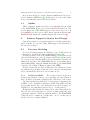
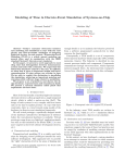
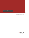
In this article, we describe softSpecification
ware aspects in our system-level deModel
sign flow [1]. We focus on three maEmbedded
jor elements (see Figure 1) that are
Processing
Software Synthesis
RTOS
Element
(part of SCE)
(Micro/OS-II)
crucial to the software support:
(ARM7TDMI)
Processor models at different
levels of abstraction.
Real-Time Operating System
(RTOS) support.
Generation of software, targeted to a selected RTOS.
RTOS targeted
SW code
Compile + Link
System Model
including ISS
Binary Image
Execution on
Target Processor
Execution on ISS
This article describes each ele- Figure 1.
Software generation
ment based on a case study for an within system level design flow.
ARM7TDMI microprocessor.
1.2
Related Work
System-level modeling has become an important issue, as a means
to improve the SoC design process. System Level Design Languages
(SLDLs) for capturing such models have been developed (e.g. SystemC
[15], SpecC [10]). Significant research effort has been invested into frameworks for system level design and software synthesis.
Benini et al. [5] introduce MPARM, an MPSoC platform simulator.
It provides a multi-processor cycle-accurate architectural simulator by
encapsulating different Instruction Set Simulators (ISSs) in SystemC. Its
main purpose is the analysis and profiling of system performance. Our
approach, on the other hand, focuses on the generation of software.
Herrara et al. [17] describe an approach for embedded software generation from SystemC that overloads SystemC class library elements in
order to use the same code for simulation and target execution. However,
the approach imposes strict requirements to the input specification.
Several commercial tool sets provide integrated simulation environments for SoC designs: e.g. ARM’s SoC Designer [3] and CoWare’s
Virtual Platform Designer [7]. While these tools focus on the ISS-based
co-simulation aspect, our approach additionally includes abstract processor modeling and software generation.
Embedded Software Development in a System-Level Design Flow
3
In previous work [24], we describe abstract simulation models for processors. Similar work includes [11]. In this paper, we focus on the design
flow to automatically generate the target software.
1.3
Outline
This document is organized as follows: Section 2.1 describes modeling
of the ARM7TDMI [4] processor from abstract to ISS-based models.
Section 2.2 reports on the RTOS support for the selected processor. In
Section 2.3, we give an overview of the software generation and targeting.
Finally, we demonstrate the resulting integrated flow in Section 3.
2.
Software Support in System Level Design
Supporting software development in system level design requires three
major elements: processor modeling, RTOS support and generation of
the embedded software.
2.1
Processor Modeling
Processor modeling captures an existing processor at different levels
of abstraction, describing its characteristics and behavior [12].
For this case study, we chose the ARM7TDMI [4], a widely used 32-bit
embedded RISC microprocessor [2]. It uses a three-stage pipeline (fetch,
decode and execute) and has single a 32-bit bus interface carrying both
instructions and data. The ARM7TDMI has two level-sensitive interrupts (nIRQ, nFIQ). Using the AMBA Design Kit [2], the ARM7TDMI
connects to the Advanced High-performance Bus (AHB).
We have captured the processor at different levels of abstraction, starting with the most abstract behavioral model, then the bus functional
model, and finally the ISS-based cycle-accurate model.
2.1.1
Behavioral Model.
The behavioral model is the most
abstract representation of the processor capturing only basic characteristics. It enables performance analysis in the early stages of the design.
The basic characteristics include the clock frequency, computing power
in MIPS, power consumption, instruction width, data width, and data
and program memory size. Some attributes are specified as ranges, for
adaptation to the particular design needs (e.g. clock frequency).
Weight tables [6] constitute the main portion of the behavioral model.
They are used for interpretation of generic profiling results and yield
comparative analysis of different design alternatives. The ARM7TDMI
behavioral model contains two weight tables, one for execution speed
and the other for footprint estimation.
4
The computation weight table correlates C-level operations with clock
cycles needed for their execution. It contains one entry for each operation
and data type stating the minimal number of execution cycles. Using
this table and the profiling information for each basic block, the system
performance can be estimated, giving an early performance comparison
between designs satisfying the fidelity property [9]. Similarly, a second
weight table contains parameters for estimating the code size.
2.1.2
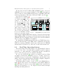
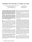
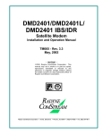
Bus Functional Model.
The Bus Functional Model
(BFM) is a pin-accurate and cycle-approximate model describing the
processor’s communication interfaces and behavior.
As shown in Figure 2, the
AMBA AHB
ARM7TDMI BFM consists of
a behavior hierarchy.
The
outer shell contains three parallel executing behaviors: processor core, Programmable Interrupt
Controller (PIC) and timer. The
core consists of two parallel executing behaviors: Hardware Abstraction Layer (HAL) and Interrupt Request (IRQ). The initially
empty HAL will contain the user
computation behaviors, which get
Figure 2. ARM7TDMI BFM.
inserted in the design flow. The
IRQ behavior houses the logic for interrupt detection and handling.
Upon receiving a core interrupt, it preempts execution of user code in
the core and starts the system interrupt handler.
The core communicates through the AMBA AHB master interface
with external components (e.g. PIC and timer). The PIC [21] maps 32
external interrupts (each maskable and configurable in priority) to the
core interrupts (nIRQ, nFIQ). The timer, disabled by default, generates
periodic interrupts needed for the timing services of the RTOS.
The bus interface is realized as a layered set of inlined channels [23].
The additional channel Protocol Wrap disables interrupts during a bus
transfer by the processor core to maintain accurate protocol timing.
ARM7TDMI
Bus Functional Model
Hardware Shell
Core
Protocol
Wrap
HAL
MAC
Link
AMBA AHB
Master
Protocol
AMBA AHB
Slave
Protocol
MAC Link
MAC
Link
MAC
Mem
Interrupt
Detect
Int.
Gen.
MAC
Link
Interrupt
Control
Logic
Timer
Control
Logic
Intr. Source
IRQ
nIRQ
nFIQ
TMC
Intr. Status
Intr. Mask
AMBA AHB
Slave
Protocol
TMV
PIC
Timer
TML
2.1.3
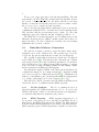
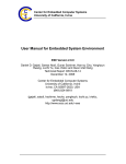
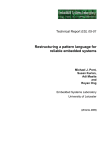
Cycle-Accurate Processor Model.
Accurate simulation of the software is offered by the cycle-accurate (CA) processor model
based on an ISS integration, therefore also called instruction set model,
and allows the execution of the final target binaries to validate the software synthesis output (Section 2.3).
5
Embedded Software Development in a System-Level Design Flow
We integrated the ISS SoftWareARM (SWARM) [8] into our model.
SWARM provides cycle-accurate simulation of the ARM data path, includes a cache model and 12MB internal memory. SWARM additionally
includes peripherals for PIC, timer, LCD and UART controller [18].
Our CA model (Figure 3)
AMBA AHB
contains the Core ISS behavior, which replaces the Core
behavior of the BFM. Inside the Core ISS, the behavior ARM7TDMI ISS wraps
the SWARM ISS and calls
User
it cycle-by-cycle. The wrapApplication
ping behavior interfaces with
µC/OS – II
ARM Port
the remaining design through
bus accesses and interrupts.
It detects SWARM external Figure 3. ARM7TDMI cycle-accurate model.
memory accesses and executes
them using the AMBA AHB master interface. It monitors the interrupt
inputs (nIRQ, nFIQ) and triggers an ISS-internal interrupt using the
SWARM API. The wrapping behavior advances the system’s simulated
time according to the ARM7 clock definition.
We disabled the SWARM internal PIC, timer and UART. Instead, we
reuse the PIC and timer of the BFM, which communicate through the
AHB. Upon startup, SWARM loads the target binary into the SWARM
internal memory (address zero), where the execution then starts from.
ARM7TDMI
Bus Functional Model
Hardware Shell
Core ISS
AMBA AHB
Master
Protocol
AMBA AHB
Slave
Protocol
Int.
Gen.
MAC
Link
ARM7TDMI_ISS
SWARM ISS
nIRQ
nFIQ
AMBA AHB
Slave
Protocol
MAC
Link
Interrupt
Control
Logic
Timer
Control
Logic
Intr. Source
TMC
Intr. Status
Intr. Mask
2.2
Interrupt
Detect
TMV
PIC
Timer
TML
Real-Time Operating System
The designer may, in the refinement process, assign multiple behaviors
to one processor. Due to the inherently sequential execution, behaviors
then have to be either statically or dynamically scheduled. An RTOS is
needed on the target processor for dynamic scheduling.
We chose the µC/OS-II [19], which is a real-time kernel providing
preemptive priority-based scheduling for up to 56 tasks. It offers deterministic services for inter-task communication, synchronization and
timing. µC/OS-II, mostly implemented in ANSI C, is highly configurable
to reduce the footprint (down to 2K bytes [19]).
The RTOS requires porting to execute on top of the SWARM ISS (see
Figure 3). We based our processor adaptation on an available ARM port
[20], and adjusted for the gcc cross-compiler [14] in terms of stack layout,
data sizes and assembly code. We adapted context switch, interrupt
handling and timing functions.
6
We use a two stage approach for the interrupt handling. The first
stage handler, OS CPU IRQ ISR(), is implemented in assembly. It saves
the context of the current task onto the stack, calls the second stage
handler, executes the OS scheduler and restores the new task’s context.
Its code is processor, compiler and OS dependent.
The second stage interrupt handler, implemented in C, performs the
communication with the PIC to determine and clear the interrupt in the
PIC, and then calls the user interrupt service routine. We chose this
multi-stage approach to limit the amount of highly specialized code.
The RTOS relies on a timer interrupt to provide timing services. Our
Hardware Abstraction Layer (HAL) contains a timer driver that configures the timer. We chose a 10ms period trading off between timing
granularity and execution overhead.
2.3
Embedded Software Generation
The embedded software generation creates the final software implementation based on the design models. The generation process is embedded into the system refinement flow as introduced in Figure 1.
The overall flow starts with an abstract specification model captured
in the SLDL SpecC [10]. Through step-wise refinement, the designer
adds design decisions and explores different alternatives. Decisions include the allocation of processing elements (PEs), mapping of computation to the PEs, selecting scheduling parameters, and defining communication parameters including the bus mapping.
One refinement output is a BFM of the entire system. In this model,
computation is mapped to processing elements [22], computation within
a processor is grouped to tasks (with priorities) [13], communication is
refined to bus primitives, and external synchronization is implemented
(e.g. polling or interrupt) based on the designer’s choice [25].
Our embedded software generation uses the BFM as an input and is
divided into the C-code synthesis and the RTOS targeting.
2.3.1
C-Code Synthesis.
The C-code synthesis is based on
[26] and translates the SLDL statements into C-code. It resolves the
behavioral hierarchy, behavior local variables and the port mappings to
C constructs using functions, structures and pointers.
2.3.2
RTOS Targeting.
RTOS targeting adapts the C-code
for execution on the target processor, scheduled by an RTOS. We use a
thin adapter, the RTOS Abstraction Layer (RAL). The RAL abstracts
from the actual RTOS implementation, providing a canonical interface.
RTOS targeting replaces SLDL statements for parallel execution into
Embedded Software Development in a System-Level Design Flow
7
calls to the RAL. It also adapts intra-processor communication to use
RAL services. Figure 4 shows the resulting software stack.
Additionally, RTOS targeting realizes external
communication
and synchronization. Most of the
SW Application
external
communication
has already been refined
Drivers
RTOS Abstraction Layer
by earlier refinement steps [25] to use a canoniRTOS
cal Media Access Control (MAC) layer, and can
Interrupts
HAL
be translated automatically by the C-code synthesis. RTOS targeting only introduces a bus and
Figure 4. SW stack.
processor-specific MAC layer implementation.
In case of interrupt based synchronization, RTOS targeting extracts
the interrupt handlers from the simulation behaviors and creates user
interrupt handlers. It generates startup code that initializes the RTOS
and registers the user interrupt handlers to the system interrupt handler.
We have extended the refinement environment’s database segregating
the software subsystems by dependencies. This allows RTOS targeting
to flexibly compose the final binary while minimizing code duplication in
the database. We added the RTOS, RTOS-specific RAL, the RTOS port,
and the board-specific HAL (containing PIC, timer and MAC code).
In the final step, the generated code is cross-compiled using gcc [14]
and linked against the target and RTOS-specific libraries. This produces
the final target binary, ready for execution on the target processor.
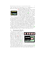
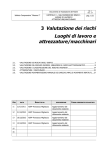
3.
Experimental Results
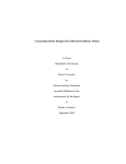
In order to show the feasibility of
our design flow, we applied it to an Break Left
Left
Right
Right
Break
Rotation Break
example from the automotive domain. Sensor Rotation
Sensor Actuator Sensor
Actuator
We implemented an anti-lock break
CAN Bus
system (see Figure 5). It uses one
Electronic Control Unit (ECU) conCPU: ARMv7
ECU
SW Application
taining an ARM7TDMI, which exCAN
Drivers
Transducer
ecutes the control application, and
RAL
RTOS
a transducer connecting to the ConInterHAL
rupts
troller Area Network (CAN) [16]. Five
AMBA AHB
sensors and actuators are connected
through the CAN bus measuring the
break paddle position, wheel speed Figure 5. Anti-lock break example.
and control the break pressure valve.
We captured this application as a specification model in SpecC [10]
and used the automatic refinement to generate the BFM inserting design decisions that yield the desired target architecture using the ear-
8
Normalized Break Power
lier described processor models. We then synthesised targeted C-code
using the extended software generation (see Section 2.3), creating an
executable binary for the ARM7TDMI processor. Using the ISS-based
model (Section 2.1.3), we co-simulate the complete system. This allows
us to validate the system and to analyze its performance in detail.
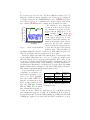
We validated correct functional
100
execution
of all created models usBreak In
Break Out
ing
a
simulated
emergency stop ma80
neuver with an initial speed of 20
60
meters
km
Figure 6
second (45mph, 72 h ).
40
shows the correlation between the
break request (Break In), as read
20
from the break paddle, and the com0
puted break pressure Break Out as0
0.5
1
1.5
2
2.5
3
serted by the left valve actuator.
Time [sec]
As the requested break pressure inFigure 6. Anti-lock break simulation. creases, the left wheel loses traction
in this scenario. Then, the anti-lock
algorithm limits the asserted break power until sufficient traction is
achieved, at which point the pressure is increased again.
Please note that we automated the refinement process and scripted the
decision input. This allows us to develop code at the specification level
while all other models are generated automatically. As a result, we did
not have to deal with low-level implementation details and could focus
on algorithm design at a higher level, gaining productivity. Furthermore,
the automated refinement process allows us to generate all models within
minutes, which enables design space exploration (although not shown for
this example) and quick implementation turn around.
To give an indicator of model
Lines
Simulation
complexity, we measured exeModel
of
Code
Time
cution times and lines of genSpec
238
0.018sec
erated code. Table 1 summaTLM
22035
0.153sec
rizes the results which show
BFM
22048
125min
that the execution time is negBFM(ISS)/C 22390/1416
208min
ligible for the abstract models
up to the TLM [24]. Starting Table 1. Model complexity in lines of code
and simulation time.
with the BFM, the execution
time dramatically increases exceeding two hours. This demo application is not computation intense
and computation is spread over time. Most simulation effort is spent on
the idle bus systems. Both, the AHB (running at 25 MHz) and the CAN
(1 MHz) use explicit clocks. Especially the CAN contributes to a steep
Embedded Software Development in a System-Level Design Flow
9
performance drop with a local clock in each node1 . The ISS-based model
is 66% slower than the BFM. Simulating the ARM (25 Mhz) cycle-bycycle adds a significant overhead. Again, with the minimal computation,
the processor spends most cycles in the idle task.
Analyzing the lines of code shows that adding the abstract models (for
processor, bus and hardware components) significantly increases the size
showing the value of automatic model generation. Also, the final user
code of 1416 lines C code is much larger than the initial specification
model. Significant detail has been added throughout the generation
process for communication, task control and boiler plate code.
4.
Conclusions
In this article, we have presented the software perspective of our
system-level design flow. In form of a ARM7TDMI based case study, we
described three major tasks necessary for software support in our flow.
First, we described the processor modeling at different abstraction
levels with the behavioral model for early exploration as our most abstract model. We reported on the pin-accurate BFM and furthermore
showed the successful integration of an ARM7 ISS into a software cycleaccurate model. Second, we discussed the adaptation of the µC/OS-II
to the ARM7 processor. Third, we reported on the embedded software
synthesis describing the RTOS targeting extension. We generate C code
for the selected RTOS and support internal communication, external
communication and synchronization.
Using an anti-lock break example, we have demonstrated the design
flow utilizing the three introduced SW support tasks. All generated
models, including the ISS-based model, simulate correctly, validating
our ability to automatically generate the final software implementation.
Using our automated refinement flow, a software developer will benefit
from describing the application at a higher level, where communication
details, processor specifics and RTOS API are hidden. Yet, the flow
produces the detailed implementation within minutes.
References
[1] S. Abdi, J. Peng, H. Yu, D. Shin, A. Gerstlauer, R. Dömer, and D. Gajski.
System-on-Chip Environment (SCE Version 2.2.0 Beta): Tutorial. Technical
Report CECS-TR-03-41, CECS, University of California, Irvine, July 2003.
[2] Advanced RISC Machines Ltd. (ARM). ARM7TDMI (Rev 3) Product Overview.
www.arm.com/pdfs/DVI0027B 7 R3.pdf.
1
Note that each bit on the CAN bus is oversampled (e.g. 12 times, [16]) for synchronization
with the sending node. Thus, a higher frequency is needed for each local clock.
10
[3] Advanced RISC Machines Ltd. (ARM). SoC Developer with MaxSim Technology. www.arm.com/products/DevTools/MaxSim.html.
[4] Advanced RISC Machines Ltd. (ARM). ARM7TDMI (Rev 4) Technical Reference Manual, 2001. www.arm.com/pdfs/DDI0210B7TDMIR4.pdf.
[5] L. Benini, D. Bertozzi, A. Bogliolo, F. Menichelli, and M. Olivier. MPARM:
Exploring the Multi-Processor SoC Design Space with SystemC. VLSI Signal
Processing, 41:169–182, 2005.
[6] L. Cai, A. Gerstlauer, and D. D. Gajski. Retargetable Profiling for Rapid, Early
System-Level Design Space Exploration. In DAC, San Diego, CA, June 2004.
[7] CoWare. Virtual Platform Designer. www.coware.com.
[8] M. Dales. SWARM 0.44 Documentation. Department of Computer Science,
University of Glasgow, Nov. 2000. www.cl.cam.ac.uk/∼mwd24/phd/swarm.html.
[9] D. D. Gajski, F. Vahid, S. Narayan, and J. Gong. Specification and Design of
Embedded Systems. Prentice Hall, 1994.
[10] D. D. Gajski, J. Zhu, R. Dömer, A. Gerstlauer, and S. Zhao. SpecC: Specification
Language and Design Methodology. Kluwer Academic Publishers, 2000.
[11] P. Gerin, H. Shen, A. Chureau, A. Bouchhima, and A. A. Jerraya. Flexible
and Executable Hardware/Software Interface Modeling for Multiprocessor SoC
Design Using SystemC. In ASPDAC, Yokohama, Japan, Jan. 2007.
[12] A. Gerstlauer, G. Schirner, D. Shin, J. Peng, R. Dömer, and D. D. Gajski.
System-On-Chip Component Models. Technical Report CECS-TR-06-10, Center
for Embedded Computer Systems, University of California, Irvine, May 2006.
[13] A. Gerstlauer, H. Yu, and D. D. Gajski. RTOS Modeling for System Level
Design. In DATE, Munich, Germany, March 2003.
[14] GNU. gcc (gcc-arm-coff version 2.95.3). ftp://ftp.gnu.org/gnu/gcc.
[15] T. Grötker, S. Liao, G. Martin, and S. Swan. System Design with SystemC.
Kluwer Academic Publishers, 2002.
[16] F. Hartwich and A. Bassemir. The Configuration of the CAN Bit Timing.
www.can.bosch.com, 1999.
[17] F. Herrera, H. Posadas, P. Snchez, and E. Villar. Systematic Embedded Software
Generation from SystemC. In DATE, 2003.
[18] Intel Corporation. Intel StrongARM SA-1110 Microporcessor Developer’s Manual. developer.intel.com/design/strong/manuals/278240.htm, October 2001.
[19] J. J. Labrosse. MicroC/OS-II: The Real-Time Kernel. CMP Books, 2002.
[20] Micriµm. µC/OS-II and The ARM Processor, Application Note AN-1011, 2004.
[21] NEC Electronics (Europe) GmbH. System-on-Chip Lite +. User’s Manual.
www.eu.necel.com/ pdf/A17158EE2V0UM00.PDF, April 2005.
[22] J. Peng, S. Abdi, and D. D. Gajski. Automatic Model Refinement for Fast
Architecture Exploration. In ASPDAC, Bangalore, India, January 2002.
[23] G. Schirner and R. Dömer. Quantitative Analysis of Transaction Level Models
for the AMBA Bus. In DATE, Munich, Germany, March 2006.
[24] G. Schirner, A. Gerstlauer, and R. Doemer. Abstract, Multifaceted Modeling of
Embedded Processors for System Level Design. In ASPDAC, Yokohama, Japan,
Jan. 2007.
[25] D. Shin, A. Gerstlauer, J. Peng, R. Dömer, and D. D. Gajski. Automatic Generation of Transaction-Level Models for Rapid Design Space Exploration. In
CODES+ISSS, Seoul, Korea, Oct. 2006.
[26] H. Yu, R. Dömer, and D. D. Gajski. Embedded Software Generation from System
Level Design Languages. In ASPDAC, Yokohama, Japan, January 2004.