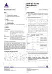
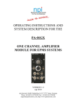
1
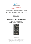
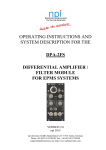
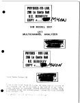
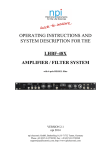
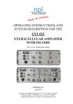
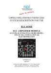
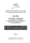
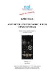
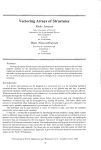
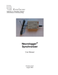
OPERATING INSTRUCTIONS AND SYSTEM DESCRIPTION FOR THE EXT-10C EXTRACELLULAR AMPLIFIER MODULE FOR EPMS SYSTEMS VERSION 2.0 npi 2012 npi electronic GmbH, Bauhofring 16, D-71732 Tamm, Germany Phone +49 (0)7141-9730230; Fax: +49 (0)7141-9730240 [email protected]; http://www.npielectronic.com EXT-10C User Manual ___________________________________________________________________________ Table of Contents 1. 2. Safety Regulations............................................................................................................ 3 EPMS-07 Modular Plug-In System.................................................................................. 4 2.1. Components of the EPMS-07 Housing ....................................................................... 4 2.2. General System Description / Operation ..................................................................... 4 2.3. EPMS-E-07 Housing ................................................................................................... 4 2.4. System Grounding ....................................................................................................... 5 2.5. Technical Data............................................................................................................. 5 3. EXT-10C .......................................................................................................................... 6 3.1. EXT-10C Components ................................................................................................ 6 3.2. System Description...................................................................................................... 6 3.3. Signal Flow Diagram................................................................................................... 6 3.4. Description of the Front Panel..................................................................................... 7 3.5. Headstage .................................................................................................................... 9 Headstage Elements..................................................................................................... 9 3.6. Operation ..................................................................................................................... 9 4. Literature .......................................................................................................................... 11 Technical Data......................................................................................................................... 12 ___________________________________________________________________________ version 2.0 page 2 EXT-10C User Manual ___________________________________________________________________________ 1. Safety Regulations VERY IMPORTANT: Instruments and components supplied by npi electronic are NOT intended for clinical use or medical purposes (e.g. for diagnosis or treatment of humans), or for any other life-supporting system. npi electronic disclaims any warranties for such purpose. Equipment supplied by npi electronic must be operated only by selected, trained and adequately instructed personnel. For details please consult the GENERAL TERMS OF DELIVERY AND CONDITIONS OF BUSINESS of npi electronic, D-71732 Tamm, Germany. 1) GENERAL: This system is design ed for use in scientific laboratories and m ust be operated only by trained staff. General safety regulations for operating electrical devices should be followed. 2) AC MAINS CONNECTION: While working with the npi systems, always adhere to the appropriate safety m easures for handling el ectronic devices. Before using any device please read manuals and instructions carefully. The device is to be operated only at 115/230 Volt 60/50 Hz AC. Please check for appropriate line voltage before connecting any system to mains. Always use a th ree-wire line cord and a m ains power-plug with a p rotection contact connected to ground (protective earth). Before opening the cabinet, unplug the instrument. Unplug the instrum ent when replacing the fu se or changing line voltage. Replace fuse only with an appropriate specified type. 3) STATIC ELECTRICITY: Electronic equipm ent is sensitive to static discharges. Some devices such as sensor inputs are equipped with very sensitive FET amplifiers, which can be damaged by electrostatic charge and must therefore be handled with care. Electrostatic discharge can be avoided by touching a gr ounded metal surface when changing or adjusting sensors. Always turn power off when adding or removing modules, connecting or disconnecting sensors, headstages or other components from the instrument or 19” cabinet. 4) TEMPERATURE DRIFT / W ARM-UP TIME: All analog electron ic systems are sensitive to temperature changes. Therefore, all electronic instruments containing analog circuits should be used only in a warmed-up condition (i.e. after internal temperature has reached steady-state values). In most cas es a war m-up period of 20-30 m inutes is sufficient. 5) HANDLING: Please p rotect the d evice from moisture, h eat, radiation and corrosive chemicals. ___________________________________________________________________________ version 2.0 page 3 EXT-10C User Manual ___________________________________________________________________________ 2. EPMS-07 Modular Plug-In System 2.1. Components of the EPMS-07 Housing The following items are shipped with the EPMS-07 housing: EPMS-07 cabinet Power cord Fuse 2 A / 1 A, slow Front covers 2.2. General System Description / Operation The npi EPMS-07 is a m odular system for processing of bioe lectrical signals in electrophysiology. The system is housed in a 19” rackmount cabinet (3U) containing a power supply and has room for up to 7 plug-in units. The plug-in units are connected to power by a bus at the rear panel. The plug-in units m ust be kept in position by four screws (M 2,5 x 10). The screws are important not only for m echanical stability but also for prope r electrical connection to the system housing. Free area must be protected with covers. In order to avoid induction of electrom agnetic noise the power supply unit, the power switch and the fuse are located at the rear of the housing. 2.3. EPMS-E-07 Housing The EPMS-E-07 housing is designed for low-noi se operation, especially for extracellular amplifiers and filters which ar e plugged in. I t operates with an exte rnal power su pply to minimize distortions of the signals caused by the power supply. The external power supply PWR-03D supports up to 3 EPMS-E housings and each housing is connected to the rear panel of the EPMS-E-07 by means of an 6-pole cable. An LED indicates that the PWR-03D is powered on. P ower switch, voltage selector and fuse are located at the rear panel. Figure 1: PWR-03D front panel view ___________________________________________________________________________ version 2.0 page 4 EXT-10C User Manual ___________________________________________________________________________ Figure 2: PWR-03D rear panel view Note: This power supply is intended to be used with npi EPMS-E systems only. 2.4. System Grounding The 19" cabinet is grounded by the power ca ble through the ground pin of the m ains connector (= protective earth). In order to avoid ground loops th e internal ground is isolated from the protective earth. The internal gr ound is used on the BNC connectors or G ROUND plugs of the m odules that are inserted in to the EPMS-07 housing. The internal ground and mains ground (= protective earth) can be conne cted by a wire using the ground plugs on the rear panel of the instrument. It is not possible to predict whether measurements will be less or more noisy with the internal ground and mains ground connected. We recommend that you try both arrangements to determine the best configuration. 2.5. Technical Data 19” rackmount cabinet, for up to 7 plug-in units Power supply: 115/230 Volts AC, 60/50 Hz, fuse 2 A / 1 A slow, 45-60 W External power supply (for EPMS-E): 115/230 Volts AC, 60/50 Hz, fuse 1.6/0.8 A, slow Dimensions: 3U high (1U= 1 3/4” = 44.45 mm ), 254 mm deep (with high voltage power supply: 354 mm deep) ___________________________________________________________________________ version 2.0 page 5 EXT-10C User Manual ___________________________________________________________________________ 3. EXT-10C 3.1. EXT-10C Components The following items are shipped with the EXT-10C system: Amplifier module for the EPMS-07 system GND- (2.6 mm banana plug) and REF. (SMB) connectors for headstage Headstage User manual 3.2. System Description The EXT-10C was designed for perform ing low noise recordings of small extracellular signals in slices or in in vivo preparations using fine tipped glass or m etal microelectrodes. The system consists of a m odule for the npi EPMS-07 modular system and a small headstage with a holding bar. The EXT-10C has a differential i nput with high input resistance for minimizing noise and the incoming signal can be com pensated for offset and capacity of the microelectrode by the two potentiometers OFFSET and C-COMP. An anal og balance m onitor makes the control of offsets easy. The recorded signal can be obtai ned either AC with GAIN of 100, 1k or 10k or DC with GAIN of 10, 100 or 1k. An optional NOTCH filter eliminates 50/60 Hz noise in AC measurements. The EXT-10C is designed to be used with the DPA-2F pr eamplifier/filter module from npi which combines additional gain stages with high- and lowpass filters. 3.3. Signal Flow Diagram The signal is passed through the EXT-10C as shown below. ___________________________________________________________________________ version 2.0 page 6 EXT-10C User Manual ___________________________________________________________________________ 3.4. Description of the Front Panel Figure 3: EXT-10C front panel view In the following description of the front panel elements each elem ent has a number tha t is related to that in Fi gure 3. The number is followed by th e name (in uppercase letters) written on the front panel and the type of the element (in lowercase letters). Then, a short description of the element is given. (1) HEADSTAGE connector The HEADSTAGE cable is connected to the unit at an 8-pin connector in the center of the module. (2) DC OUTPUT connector BNC connector providing the am plified signal DC coupled. The a mplification factor is set by the GAIN DC switch (3). The DC OUTPUT is always unfiltered. ___________________________________________________________________________ version 2.0 page 7 EXT-10C User Manual ___________________________________________________________________________ (3) GAIN DC switch Switch to set the GAIN of the outgoing DC signal. Three GAIN factors are available: x10, x100 or x1k. (4) C-COMP. potentiometer Control for com pensation of stray capaciti es of the m icroelectrode (10 turn potentiometer, range 0-20 pF). Due to the positive feedback circuit overcompensation of the capacity will lead to oscillations which may damage the cell. (5) POTENTIAL x10 meter The analog POTENTIAL monitor displays the offset in the range of 30 mV and is used for optimal cancellation of the OFFSET. (6) –OVER +OVER LEDs LEDs that indica te if the am plifier 10% below it’s positive or negative lim (±10 V). The linear range of the amplifier is 12 V. it (7) OFFSET potentiometer 10 turn potentiometer to compensate for the OFFSET of a DC signal. Note: Position 5 on the OFFSET control corresponds to 0 mV offset. (8) GAIN AC switch Switch to set the GAIN of the outgoing AC signal. Three GAIN factors are available: x100, x1k or x10k. (9) AC OUTPUT connector BNC connector providing the am plified signal AC coupled. The a mplification factor is set by switch (8). (10) NOTCH switch (optional) Switch to set the NOTCH filter (50 Hz / 60 Hz ) or to bypass the NOTCH filter (switch position OFF) for AC measurements. ___________________________________________________________________________ version 2.0 page 8 EXT-10C User Manual ___________________________________________________________________________ 3.5. Headstage Figure 4: electrode holder (optional) and headstage of the EXT 10-2F Headstage Elements 1 2 3 4 PEL: BNC connector for the electrode holder (measuring electrode) REF: SMB connector for the reference electrode GND: Ground connector Holding bar On request, P EL can be im plemented using 1 mm or connectors. 2 mm banana jacks or using SMB Very Important: EXT 10C headstages are always labeled “EXT” (see Figure 4) and must not be exchanged with headstages from npi electronic’s desktop EXT amplifiers, e.g. the EXT-2F which is labeled “EXT-02”! Also Important: The shield of the BNC connector of shield, and must not be connected to ground. 3.6. the headstage is connected to driven Operation Extracellular measurements are mostly done in slices or in vivo, where distortions of the signal caused by other instrum ents and the animal itself are very co mmon. Additionally, extracellular signals are very sm all and have to be a mplified enormously. The drawback is that noise is amplified as well. Ther efore, the headstage of the EXT- 10C is equipped with a differential input that m inimizes noise pick-up. Differential m eans, that the signal for the amplifier is the difference between the positive ( +) (PEL) and negative (-) (REF.) input of the headstage. This results in canceling of all signals which both electrodes record, e.g. noise. For differential measurements, both inputs of the headstage (REF. and P EL) are connected to microelectrodes using cables with grounde d enclosure or electrode holders. P EL is connected to the measuring electrode and REF. to the re ference electrode. The experimental chamber is grounded by an Ag-AgCl pellet (or an AGAR br idge) connected to G ND of the headstage (see Figure 5). ___________________________________________________________________________ version 2.0 page 9 EXT-10C User Manual ___________________________________________________________________________ If differential m easurement is not required (single-ended measurement configuration, see Figure 5), the REF inp ut must be connected to ground (GND). The amplifier is in an undefined state, if the REF is left open, an d can go into saturation m aking reliable measurements impossible. Figure 5: headstage connections, A: differential measurement, B: single-ended measurement ___________________________________________________________________________ version 2.0 page 10 EXT-10C User Manual ___________________________________________________________________________ 4. Literature Barmashenko, G., Eysel, U. T., & Mittm ann, T. (2003). Changes in intracellular calcium transients and LTP in the surround of visual cortex lesions in rats. Brain Res. 990, 120128. Boulton, A. A., Baker, G. B. & Va nderwolf, C. H. (eds.) (1990). Neurophysiological Techniques, Basic Methods and Concepts. Humana Press, Clifton, New Jersey. Both, M., Bahner, F., Bohlen Und, H. O., & Draguhn, A. (2008). Propagation of specific network patterns through the mouse hippocampus. Hippocampus. Hartwich, K., Pollak, T., & Klausberger, T. (2 009). Distinct Firing Patterns of Identified Basket and Dendrite-Targeting Interneurons in the Prefrontal Cort ex during Hippocampal Theta and Local Spindle Oscillations. Journal of Neuroscience 29, 9563-9574. Huemmeke, M., Eysel, U. T., & Mittm ann, T. (2002). Metabotrop ic glutamate receptors mediate expression of LTP in slices of rat visual cortex. Eur.J.Neurosci. 15, 1641-1645. Huemmeke, M., Eysel, U. T., & Mittm ann, T. (2004). Lesion-indu ced enhancement of LTP in rat visual co rtex is mediated by NMDA receptors containing the NR2B subunit. J Physiol 559 , 875-882. Schulz, D., Huston, J. P., Jezek, K., Haas, H. L., Roth-Harer, A., Selbach, O., & Luhmann, H. J. (2002 ). Water maze performance, exp loratory activity, inhibitory avoidance and hippocampal plasticity in aged s uperior and inferior learners. Eur.J.Neurosci. 16, 21752185. Kettenmann, H. & Grantyn, R. (eds.) (1992). Wiley-Liss, New York Practical Electrophysiological Methods. Lalley, P.M., A.K. Moschovakis and U. Windhorst (1999) Electrical Activity of Individual Neurons In Situ: Extra- and Intracellular Recording, in: U. Windhorst and H. Johansson (eds.) Modern Techniques in Neuroscience Research, Springer, Berlin, New York Müller, Ch.M. (1992) E xtra- and Intracellular Recording in the Slice, in: Kettenm ann, H. & Grantyn, R. (eds.) Practical Electro-physiological Methods, Wiley-Liss, New York Reichinnek, S., Kunsting, T., Draguhn, A., & Bo th, M. (2010). Field po tential signature of distinct multicellular activity patterns in the m ouse hippocampus. J Neurosci. 30, 1544115449. Ogden, D. (ed.) (1992) Micr oelectrode Techniques - The P lymouth Workshop Handbook, Second Edition, The Company of Biologists Ltd., Cambridge Seidenbecher, T. and H.C. Pape (2001) Contri bution of intralam inar thalamic nuclei to spike-and-wave-discharges during spontaneous seizures in a genetic rat model of absence epilepsy, European Journal of Neuroscience, Vol. 13:1537-1546 Weiss, E. K., Krupka, N., Bahner, F., Bot h, M., & Draguhn, A. (2008). Fast effects of glucocorticoids on m emory-related network oscillations in the mouse hippocam pus. J.Neuroendocrinol. 20, 549-557. Werdin, F., Grussinger, H., Jam inet, P., Kraus, A., Manoli, T., Danker, T., Guenther, E., Haerlec, M., Schaller, H. E., & Sinis, N. (2009). An improved electrophysiological method to study peripheral nerve regeneration in rats. J Neurosci.Methods. 182, 71-77. Windhorst, U. and H. Johansson (eds.) ( 1999) Modern Techniques in Neuroscience Research, Springer, Berlin, Heidelberg, New York ___________________________________________________________________________ version 2.0 page 11 EXT-10C User Manual ___________________________________________________________________________ Technical Data Differential Input: CMR >90 dB at 1 kHz (tested with 0 input resistance) Input resistance: >1012 , range ±1 V Output DC: selectable gain (x10, x100, x1k) Output range: ±12 V into 1 k / ±1 V into 50 load Output AC: selectable gain (x100, x1k, x10k) Output range: ±12 V into 1 k / ±1 V into 50 load corner frequency 10 Hz NOTCH filter 50/60 Hz (optional) Offset compensation: 10 turn potentiometer, ±100 mV Potential monitor: analog display for the electrode offset, range: ±30 mV Capacity compensation: 0-20 pF, 10 turn potentiometer Size: front panel 12 HP (60.6 mm) x 3U (128,5 mm), 7” (175 mm) deep Headstage Size: 70 x 26 x 26 mm Holding Bar: length: 150 mm; diameter: 8 mm. EPMS-07 SYSTEM Power Requirements: 115/230 V AC, 60/50 Hz, fuse 2 A / 1 A, slow, 45-60 W (dependent on the modules plugged in) Dimensions: 19” rackmount cabinet, 3U high (1U = 1 3/4” = 44.45 mm) ___________________________________________________________________________ version 2.0 page 12