1
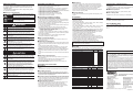
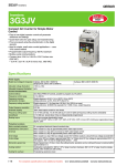
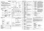
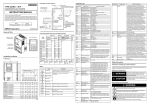
Safety Precautions Precautions for Safe Use Indications and Meanings of Safety Information Installation and Storage In this user’s Manual, the following precautions and signal words are used to provide information to ensure the safe use of the 3G3MX2 Inverter. The information provided here is vital to safety. Strictly observe the precautions provided. Meanings of Signal Words WARNING CAUTION Indicates an imminently hazardous situation which, if not avoided, will result in minor or moderate injury, or may result in serious injury or death. Additionally there may be significant property damage. Indicates a potentially hazardous situation which, if not avoided, may result in minor or moderate injury or in property damage. Alert Symbols in this Document WARNING Turn off the power supply and implement wiring correctly. Not doing so may result in a serious injury due to an electric shock. Wiring work must be carried out only by qualified personnel. Not doing so may result in a serious injury due to an electric shock. Be sure to ground the unit. Not doing so may result in a serious injury due to an electric shock or fire. (200V class:type-D grounding, 400V class:type-C grounding) Do not remove the front cover during the power supply and 10 minutes after the power shutoff. Doing so may result in a serious injury due to an electric shock. Do not operate the Operator or switches with wet hands. Doing so may result in a serious injury due to an electric shock. Inspection of the Inverter must be conducted after the power supply has been turned off. Not doing so may result in a serious injury due to an electric shock. The main power supply is not necessarily shut off even if the emergency shut off function is activated. Do not change wiring, slide switches, optional devices, or replace cooling fans while power is being supplied. Doing so may result in a serious injury due to an electric shock. Do not touch the Inverter fins, braking resistors and the motor, which become too hot during the power supply and for some time after the power shutoff. Doing so may result in a burn. CAUTION Do not connect resistors to the terminals (PD/+1, P/+2, N/-) directly. Doing so might result in a small-scale fire, heat generation or damage to the unit. Install a stop motion device to ensure safety. Not doing so might result in a minor injury. (A holding brake is not a stop motion device designed to ensure safety.) Be sure to use a specified type of braking resistor / regenerative braking unit. In case of a braking resistor, install a thermal relay that monitors the temperature of the resistor. Not doing so might result in a moderate burn due to the heat generated in the braking resistor / regenerative braking unit. Configure a sequence that enables the Inverter power to turn off when unusual overheating is detected in the braking resistor / regenerative braking unit. The Inverter has high voltage parts inside which, if short-circuited, might cause damage to itself or other property. Place covers on the openings or take other precautions to make sure that no metal objects such as cutting bits or lead wire scraps go inside when installing and wiring. Take safety precautions such as setting up a molded-case circut breaker(MCCB) that matches the Inverter capacity on the power supply side. Not doing so might result in damage to property due to the short circuit of the load. Do not dismantle, repair or modify the product. Doing so may result in an injury. Do not store or use the product in the following places. · Locations subject to direct sunlight. · Locations subject to ambient temperature exceeding the specifications. · Locations subject to relative humidity exceeding the specifications. · Locations subject to condensation due to severe temperature fluctuations. · Locations subject to corrosive or flammable gases. · Locations subject to exposure to combustibles. · Locations subject to dust (especially iron dust) or salts. · Locations subject to exposure to water, oil, or chemicals. · Locations subject to shock or vibration. Transporting, Installation and Wiring · Do not drop or apply a strong impact on the product. Doing so may result in damaged parts or malfunction. · Do not hold by the front cover, but hold by the fins during transportation. · Do not connect an AC power supply voltage to the control input / output terminals. Doing so may result in damage to the product. · Be sure to tighten the screws on the terminal block securely. Wiring work must be done after installing the unit body. · Do not connect any load other than a three-phase inductive motor to the U, V and W output terminals. · Take sufficient shielding measures when using the product in the following locations. Not doing so may result in damage to the product. Locations subject to static electricity or other forms of noise. Locations subject to strong magnetic fields. Locations close to power lines. · If a parameter is set incorrectly when starting up, adjusting, maintaining, or replacing, an unexpected operation may occur. Perform the operation after enough confirmation. · When using DriveProgramming, confirm that the program data is downloaded normally before starting operation. Main Circuit Power Supply · Confirm that the rated input voltage of the Inverter is the same as AC power supply voltage. Operation and Adjustment · Be sure to confirm the permissible range of motors and machines before operation because the inverter speed can be changed easily from low to high. · Provide a separate holding brake if necessary. · If the DriveProgramming stops during multi-function output, the output status is held. Take safety precautions such as stopping peripheral devices. · Even if the inverter power supply is turned off, the counter-electromotive force occurs while the PM motor rotates, which may result in electric shock. Do not remove the terminal block cover of the inverter until the PM motor stops. Maintenance and Inspection · Be sure to confirm safety before conducting maintenance, inspection or parts replacement. · The life of the capacitor depends on the ambient temperatures. Refer to the product life curve shown in User’ s Manual. When the capacitor stops operating at the end of its service life, the Inverter must be replaced. Precautions for Correct Use Installation · Mount the product vertically on a wall with the product’ s longer sides upright. The material of the wall has to be nonflammable such as a metal plate. Error Retry Function Maintenance · The Inverter consists of many parts, which must operate properly to maximize its capabilities. Some electronic parts require maintenance depending on their operating conditions. To ensure proper operation of the Inverter over a long period of time, be sure to perform periodic inspections and replace parts according to their service life. (Excerpt from “Recommendations for Periodic Inspections of Generalpurpose Inverters” issued by JEMA) · It is necessary to use optional EMC filter to comply with EMC directive (EN61800-3). · For earthing, selection of cable, and any other conditions for EMC compliance, please refer to the manual for installation. OMRON Corporation Shiokoji Horikawa, Shimogyo-ku, Kyoto, 600-8530, Japan Product Disposal · Comply with the local ordinance and regulations when disposing of the product. UL Cautions The warnings and instructions in this section summarizes the procedures necessary to ensure an inverter installation complies with Underwriters Laboratories guidelines. · Use 60/75°C Cu wire only. (For models:3G3MX2-A2001, -A2002, -A2004, -A2007, -AB015, -AB022, -A4004, -A4007, -A4015, -A4022, and -A4030) · Use 75°C Cu wire only. (For models:3G3MX2-AB001, -AB002, -AB004, -AB007, -A2015, -A2022, -A2037, -A2055, -A2075, -A2110, -A2150, -A4040, -A4055,-A4075, -A4110 and -A4150) · Suitable for use on a circuit capable of delivering not more than 100,000 rms Symmetrical Amperes, 240 or 480 Volts Maximum. · When Protected by CC, G, J, or R Class Fuses, or when Protected By A Circuit Breaker Having An Interrupting Rating Not Less Than 100,000 rms Symmetrical Amperes, 240 or 480 Volts Maximum. · Install device in pollution degree 2 environment. · Maximum surrounding air temperature rating of 50°C · Solid State motor overload protection reacts with max. 150 % of FLA. · Integral solid state short circuit protection does not provide branch circuit protection. Branch circuit protection must be provided in accordance with the National Electric Code and any additional local codes. · Motor over temperature protection is not provided by the drive. Omron Europe B.V. Wegalaan 67-69, NL-2132 JD Hoofddorp, The Netherlands Safety For use of the drive as a safety device, to meet the requirements of the ISO13849-1, please refer to user’s manual. For KC Marking Only ἽGὤὤ ஂ㛹ⱨ㟝Gⵝ㋕䋩㐔ὤ㣄㣠ஃ G 㢨Gὤὤ⏈G㛹ⱨ㟝OἽPG㤸㣄䑀㤵䚝ὤὤ⦐㉐G䑄⬘㣄G❄⏈G㇠㟝㣄⏈G㢨G 㥄㡸G㨰㢌䚌㐐ὤGⵈ⢰⮤SGᴴ㥉㞬㢌G㫴㜡㜄㉐G㇠㟝䚌⏈Gᶷ㡸G⯝㤵㡰⦐G 䚝⏼␘U AVERTISSEMENT: ne retirez pas le capot avant pendant l’alimentation et 10 minutes après l’arrêt de l’alimentation. Cela peut entraîner de grave blessure due à un choc électrique. Fuse Size The Inverter shall be connected with a UL Listed Cartridge Nonrenewable fuse, rated 600Vac with the current ratings as shown in the table below. Model No. Type Rating 3G3MX2-AB001, -AB002, -AB004 3G3MX2-AB007 3G3MX2-AB015 3G3MX2-AB022 3G3MX2-A2001, -A2002, -A2004 3G3MX2-A2007, -A2015 3G3MX2-A2022 3G3MX2-A2037 3G3MX2-A2055, -A2075 3G3MX2-A2110, -A2150 3G3MX2-A4004, -A4007, -A4015, -A4022 3G3MX2-A4030, -A4040 3G3MX2-A4055, -A4075 3G3MX2-A4110, -A4150 Class J 10A, AIC 200kA 20A, AIC 200kA 30A, AIC 200kA 30A, AIC 200kA 10A, AIC 200kA 15A, AIC 200kA 20A, AIC 200kA 30A, AIC 200kA 60A, AIC 200kA 80A, AIC 200kA 10A, AIC 200kA 15A, AIC 200kA 30A, AIC 200kA 50A, AIC 200kA Terminal symbols and Screw size Model No. 3G3MX2-AB001, -AB002, -AB004 3G3MX2-AB007 3G3MX2-AB015, -AB022 Screw Required Size Torque(N-m) Wire Range M3.5 1.0 AWG16 (1.3 mm2) M4 1.4 AWG12 (3.3 mm2) M4 1.4 AWG10 (5.3 mm2) M3.5 1.0 AWG16 (1.3 mm2) 3G3MX2-A2015 M4 1.4 AWG14 (2.1 mm2) 3G3MX2-A2022 M4 1.4 AWG12 (3.3 mm2) Non-Stop Function at Momentary Power Interruption 3G3MX2-A2037 M4 1.4 AWG10 (5.3 mm2) · Do not come close to the machine when selecting reset in the non-stop function at momentary power interruption selection (b050) because the machine may abruptly start after the power is turned on. 3G3MX2-A2055, -A2075 M5 3.0 3G3MX2-A2110 M6 3.9 to 5.1 · Do not come close to the machine when using the error retry function because the machine may abruptly start when stopped by an alarm. · Be sure to confirm the RUN signal is turned off before resetting the alarm because the machine may abruptly start. Conformance to EC Directives 3G3MX2-A2001, -A2002, -A2004, -A2007 AWG6 (13 mm2) AWG4 (21 mm2) 3G3MX2-A2150 M8 5.9 to 8.8 AWG2 (34 mm2) Operation Stop Command 3G3MX2-A4004, -A4007, -A4015 M4 1.4 AWG16 (1.3 mm2) · Provide a separate emergency stop switch because the STOP Key on the Operator is valid only when function settings are performed. · When checking a signal during the power supply and the voltage is erroneously applied to the control input terminals, the motor may start abruptly. Be sure to confirm safety before checking a signal. 3G3MX2-A4022, -A4030 M4 1.4 AWG14 (2.1 mm2) 3G3MX2-A4040 M4 1.4 AWG12 (3.3 mm2) 3G3MX2-A4055, -A4075 M5 3.0 AWG10 (5.3 mm2) 3G3MX2-A4110, -A4150 M6 3.9 to 5.1 AWG6 (13 mm2) SUITABILITY FOR USE Omron Companies shall not be responsible for conformity with any standards, codes or regulations which apply to the combination of the product in the buyer’s application or use of the product. At buyer’s request, Omron will provide applicable third party certification documents identifying ratings and limitations of use which apply to the product. This information by itself is not sufficient for a complete determination of the suitability of the product in combination with the end product, machine, system, or other application or use. Buyer shall be solely responsible for determining appropriateness of the particular product with respect to Buyer’s application, product or system. Buyer shall take application responsibility in all cases. NEVER USE THE PRODUCT FOR AN APPLICATION INVOLVING SERIOUS RISK TO LIFE OR PROPERTY OR IN LARGE QUANTITIES WITHOUT ENSURING THAT THE SYSTEM AS A WHOLE HAS BEEN DESIGNED TO ADDRESS THE RISKS, AND THAT THE OMRON PRODUCT(S) IS PROPERLY RATED AND INSTALLED FOR THE INTENDED USE WITHIN THE OVERALL EQUIPMENT OR SYSTEM. OMRON Corporation Industrial Automation Company Tokyo, JAPAN Contact: www.ia.omron.com Regional Headquarters OMRON EUROPE B.V. Wegalaan 67-69, NL-2132 JD Hoofddorp The Netherlands Tel: (31)2356-81-300 Fax: (31)2356-81-388 OMRON ELECTRONICS LLC One Commerce Drive Schaumburg, IL 60173-5302 U.S.A. Tel: (1) 847-843-7900 Fax: (1) 847-843-7787 OMRON ASIA PACIFIC PTE. LTD. No. 438A Alexandra Road # 05-05/08 (Lobby 2), Alexandra Technopark, Singapore 119967 Tel: (65) 6835-3011 Fax: (65) 6835-2711 OMRON (CHINA) CO., LTD. Room 2211, Bank of China Tower, 200 Yin Cheng Zhong Road, Pu Dong New Area, Shanghai, 200120, China Tel: (86) 21-5037-2222 Fax: (86) 21-5037-2200 Note: Specifications subject to change without notice. 2272699-9B NT321XC-EN