1
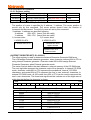
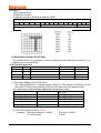
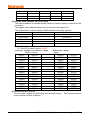
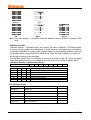
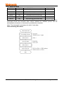
13. Initializing flow chart
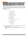
Initialize of LCM is required for “Mode set”, “Control word set”after power on. Following is
the one example of initialize procedure of 240x64 dots display (In case of 6x8 dots/font:
FS=H).
Command
Power on
Hard reset ( use reset terminal )
Mode set
Control word set
Graphic home position set
( Graphic home position 000H )
Number of graphic area set
( Graphic 40x6 dots )
Text home position set
( Text home position 1000H )
Number of text area set
( text 40 column )
Initialize end , Data Write
Address pointer set
( address pointer 0000H )
Data Write ( graphic )
Address pointer set
( address pointer 1000H )
Data write ( text )
Display Mode Set ( text/graphic on )
C/D
D7 --------------D0 Note
Power on
RESET=“L” ( 1msec minimum after VDD>4.75V )
1
10000000
“OR” mode
0
0
1
0
0
1
0
0
1
0
0
1
00000000
00000000
01000010
00101000
00000000
01000011
00000000
00010000
01000000
00101000
00000000
01000001
graphic home address
0
0
1
0
1
0
1
x
0
0
1
0
1
0
1
x
1
00000000
00000000
00100100
01010101
11100000
10101010
11100000
xxxxxxxx
00000000
00010000
00100100
00110100
11000000
00101111
11000000
xxxxxxxx
10011100
graphic home address
command
number of area
command
text home address
command
number of area
command
command
Data
command
Data
command
text home address
command
Data
command
Data
command
Note:
1. “status check”should be inserted between all command and data.
2. Display mode set register is cleared ( no display mode ) by the hard reset , and no
display is appeared on LCD panel. And just after “Display Mode set 9CH”, written
data is display on the LCD.
TG12864F-04WA0_A00
Page 24 of 27