1
User Manual
netANALYZER
netANALYZER Card PCI RTE - NANL-C500-RE
netANALYZER portable Device PCIe RTE - NANL-B500E-RE
netANALYZER portable Device RTE - NANL-B500G-RE
netANALYZER Software V1.5.x.x
NANL-C500-RE
NANL-B500E-RE
NANL-B500G-RE
Installation, Operation and Hardware Description
Hilscher Gesellschaft für Systemautomation mbH
www.hilscher.com
DOC091110UM14EN | Revision 14 | English | 2014-05 | Released | Public
Table of Contents
2/171
Table of Contents
1
INTRODUCTION.........................................................................................................7
1.1
About the User Manual ...............................................................................................7
1.1.1
1.1.2
1.1.3
1.2
Contents of the Product DVD ...................................................................................11
1.2.1
1.2.2
1.2.3
1.3
Copyright ............................................................................................................13
Important Notes ..................................................................................................13
Exclusion of Liability ...........................................................................................14
Warranty .............................................................................................................14
Export Regulations .............................................................................................15
Registered Trademarks......................................................................................15
Obligation to read and understand the Manual ..................................................15
Hilscher Software License Agreement ...............................................................15
SAFETY ....................................................................................................................16
2.1
General Note ............................................................................................................16
2.2
Intended Use ............................................................................................................16
2.3
Personnel Qualification.............................................................................................16
2.4
Safety Instructions to avoid Personal Injury..............................................................17
2.4.1
2.5
Electrical Shock Hazard (NANL-C500-RE) ........................................................17
Safety Instructions to avoid Property Damage .........................................................18
2.5.1
2.5.2
2.5.3
2.5.4
2.5.5
2.5.6
3
Directory Structure of the DVD...........................................................................11
Documentations netANALYZER ........................................................................12
What's New.........................................................................................................12
Legal Notes...............................................................................................................13
1.3.1
1.3.2
1.3.3
1.3.4
1.3.5
1.3.6
1.3.7
1.3.8
2
List of Revisions ...................................................................................................8
Note on Hardware, Firmware, Driver and Software Versions ..............................9
Conventions in this Manual ................................................................................10
Device Destruction by exceeding allowed Supply Voltage ................................18
Device Destruction by exceeding allowed Signaling Voltage ............................18
Device Destruction by exceeding allowed External IO Interface Output Current
............................................................................................................................19
Damage of externally attached Hardware..........................................................19
Electrostatically sensitive Devices (NANL-C500-RE) ........................................20
Assignment of wrong IP addresses, malfunction (NANL-B500G-RE) ...............20
2.6
Labeling of Safety Messages....................................................................................21
2.7
References Safety ....................................................................................................21
DESCRIPTION AND REQUIREMENTS ...................................................................22
3.1
Introduction to the netANALYZER ............................................................................22
3.1.1
3.2
Recording and analyzing Data Traffic ................................................................23
System Requirements ..............................................................................................25
3.2.1
3.2.2
Hardware Requirements ....................................................................................25
Power Supply and Host Interface.......................................................................26
netANALYZER | Installation, Operation and Hardware Description
DOC091110UM14EN | Revision 14 | English | 2014-05 | Released | Public
© Hilscher, 2007-2014
Table of Contents
3.2.3
3.3
4
5
6
Maximum permissible Output Current (external IO Interface) ...........................27
Software Requirements ............................................................................................28
GETTING STARTED.................................................................................................29
4.1
Notes for Installation and Operation .........................................................................29
4.2
Notes for Wireshark before V1.7.1 ...........................................................................30
4.3
Overview Software and Hardware Installation..........................................................31
4.4
Overview how to update Hardware, Software and Driver .........................................32
4.5
Overview Settings an Analysis Methods...................................................................33
DEVICE DRAWINGS NETANALYZER HARDWARE ...............................................35
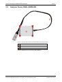
5.1
Analyzer Card NANL-C500-RE ................................................................................35
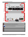
5.2
Analyzer Device NANL-B500E-RE ...........................................................................36
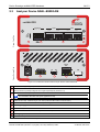
5.3
Analyzer Device NANL-B500G-RE...........................................................................38
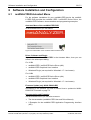
SOFTWARE INSTALLATION AND CONFIGURATION ............................................39
6.1
netANALYZER Autostart Menu ................................................................................39
6.2
How to install the netANALYZER Driver and Software.............................................40
6.2.1
6.2.2
6.2.3
6.2.4
6.2.5
Installation netANALYZER / netSCOPE Device Driver......................................42
Installation Remote Access Windows Client (only NANL-B500G-RE)...............44
Installation netANALYZER Software ..................................................................47
Default Paths for .hea Files and Software Filters...............................................50
Installation Ethernet Device Configuration (only NANL-B500G-RE)..................51
6.3
Configuration of the IP Address (only NANL-B500G-RE).........................................54
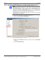
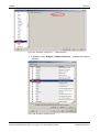
6.4
Open Documentation or Examples ...........................................................................55
6.5
Display and Settings in Wireshark ............................................................................56
6.5.1
6.5.2
7
3/171
netANALYZER Info Block in extended .pcap File Format..................................56
Display Port Number in Wireshark Packet List ..................................................57
NETANALYZER HARDWARE INSTALLATION ........................................................60
7.1
Safety Messages on Personal Injury ........................................................................60
7.1.1
7.2
Electrical Shock Hazard (NANL-C500-RE) ........................................................60
Property Damage Messages ....................................................................................61
7.2.1
7.2.2
7.2.3
7.2.4
7.2.5
7.2.6
Device Destruction by exceeding allowed Supply Voltage ................................61
Device Destruction by exceeding allowed Signaling Voltage ............................61
Device Destruction by exceeding permissible External IO Interface Output
Current................................................................................................................61
Damage of externally attached Hardware..........................................................62
Electrostatically sensitive Devices (NANL-C500-RE) ........................................62
Assignment of wrong IP addresses, malfunction (NANL-B500G-RE) ...............63
7.3
Mounting Analyzer Card NANL-C500-RE to the PC.................................................64
7.4
Connecting Analyzer Device NANL-B500E-RE to the Notebook .............................65
7.5
Connecting Analyzer Device NANL-B500G-RE to the PC........................................66
7.6
Inserting netANALYZER Hardware into the Communication Link ............................67
netANALYZER | Installation, Operation and Hardware Description
DOC091110UM14EN | Revision 14 | English | 2014-05 | Released | Public
© Hilscher, 2007-2014
Table of Contents
7.6.1
7.6.2
7.6.3
7.6.4
8
Application Case 1..............................................................................................67
Application Case 2..............................................................................................68
Application Case 3..............................................................................................69
Application Case 4..............................................................................................70
7.7
Auto-Crossover and Port-Switching..........................................................................72
7.8
How to update the NANL-B500G-RE Firmware .......................................................73
7.9
Demounting Analyzer Card NANL-C500-RE ............................................................77
NETANALYZER SOFTWARE ...................................................................................78
8.1
Starting the netANALYZER Software .......................................................................78
8.1.1
8.1.2
8.1.3
8.1.4
8.1.5
8.1.6
Starting and closing the netANALYZER Software .............................................78
Starting the netANALYZER Software multiple Times ........................................78
Verification for Hardware and Device Driver ......................................................78
Starting netANALYZER Software without Hardware Installation .......................79
Selecting netANALYZER Device........................................................................80
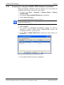
Scanning for changed netANALYZER Hardware Installation ............................82
8.2
netANALYZER Main Window ...................................................................................83
8.3
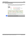
Link Speed Information.............................................................................................86
8.4
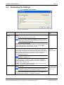
Performing File Settings ...........................................................................................87
8.5
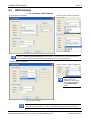
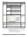
GPIO Settings...........................................................................................................89
8.6
Filter Settings for the Hardware Filters .....................................................................91
8.6.1
8.6.2
Selection List Filter Configuration.......................................................................93
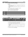
Defining, saving, loading Filter Settings .............................................................94
8.7
PHY Settings ............................................................................................................95
8.8
Extended Software Filter Settings ............................................................................96
8.8.1
8.8.2
8.8.3
8.8.4
8.8.5
8.8.6
9
4/171
Filter Principles ...................................................................................................96
Creating Filter Entries and Identification ............................................................96
Extended Software Filters ..................................................................................97
Moving Filter Entry..............................................................................................99
Add Filter Entry.................................................................................................100
Add Identification Entry ....................................................................................105
8.9
Analysis Configuration ............................................................................................106
8.10
About Hilscher netANALYZER ...............................................................................107
NETANALYZER ANALYSIS METHODS .................................................................108
9.1
Data Capturing........................................................................................................108
9.1.1
9.1.2
9.1.3
9.1.4
9.1.5
9.1.6
9.2
Starting Capturing.............................................................................................108
Converting Binary Files into WinPcap Format .................................................109
Timestamp........................................................................................................112
Input Signal as pseudo Frame .........................................................................113
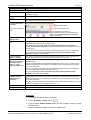
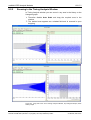
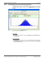
Determining Cycle Time and Forwarding Time (Capture Data Mode).............114
Transparent Mode ............................................................................................115
Timing Analysis.......................................................................................................116
9.2.1
9.2.2
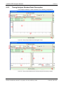
Starting Timing Analysis...................................................................................116
The Timing Analysis Window ...........................................................................116
netANALYZER | Installation, Operation and Hardware Description
DOC091110UM14EN | Revision 14 | English | 2014-05 | Released | Public
© Hilscher, 2007-2014
Table of Contents
9.2.3
9.2.4
9.2.5
9.2.6
9.2.7
9.3
11
10.1
Notes about Troubleshooting..................................................................................134
10.2
Status Bar Messages..............................................................................................135
10.3
Overview Error Codes ............................................................................................136
10.4
Important Error Codes, Causes and Troubleshooting ............................................137
LEDS .......................................................................................................................140
11.1
LEDs NANL-C500-RE and NANL-B500E-RE.........................................................140
11.2
LEDs NANL-B500G-RE..........................................................................................141
12.1
Power Supply NANL-B500E-RE.............................................................................143
12.2
Power Supply NANL-B500G-RE ............................................................................144
12.3
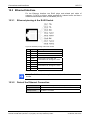
Ethernet Interface ...................................................................................................145
12.4
Ethernet pinning at the RJ45 Socket................................................................145
Data of the Ethernet Connection ......................................................................145
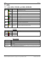
External IO Interface...............................................................................................146
12.4.1
14
SYS, STA0, STA1, IO, LINK und RX (Front Side) ...........................................141
Fatal Error.........................................................................................................142
LINK-ACT and LINK-1000/LINK100 (Reverse Side)........................................142
CONNECTIONS AND INTERFACES......................................................................143
12.3.1
12.3.2
13
Starting Netload Analysis .................................................................................128
The Netload Analysis Window..........................................................................129
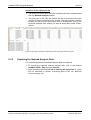
Capturing the Netload Analysis Data ...............................................................133
TROUBLESHOOTING, STATUS MESSAGES AND ERROR CODES ................... 134
11.2.1
11.2.2
11.2.3
12
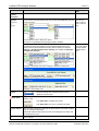
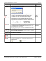
Timing Analysis Window Detail Description .....................................................119
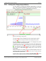
Scaling in the Timing Analysis Window............................................................122
Zooming in the Timing Analysis Window .........................................................123
Examples for the Possibilities of the Timing Analysis ......................................124
Determining Cycle Time and Forwarding Time................................................127
Netload Analysis .....................................................................................................128
9.3.1
9.3.2
9.3.3
10
5/171
Connection Cable for external IO Interface......................................................146
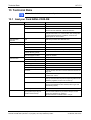
TECHNICAL DATA .................................................................................................147
13.1
Analyzer Card NANL-C500-RE ..............................................................................147
13.2
Analyzer Device NANL-B500E-RE .........................................................................149
13.3
Analyzer Device NANL-B500G-RE.........................................................................151
ANNEX ....................................................................................................................153
14.1
Hardware Update for NXANL 500-RE Rev 2 and Rev 3 ........................................153
14.2
Hints on how to install the netANALYZER Driver manually ....................................155
14.3
Wireshark netANALYZER Plugin before Wireshark 1.7.1 ......................................156
14.3.1
14.3.2
14.3.3
14.3.4
Uninstalling manually installed Plugin ..............................................................156
Installing netANALYZER Plugin via Setup .......................................................156
Default Paths for the netANALYZER Plugin ....................................................159
Installing Plugin manually.................................................................................159
netANALYZER | Installation, Operation and Hardware Description
DOC091110UM14EN | Revision 14 | English | 2014-05 | Released | Public
© Hilscher, 2007-2014
Table of Contents
14.3.5
6/171
Checking netANALYZER Info Block.................................................................160
14.4
Activating GPIO Dissector for Wireshark before V1.7.1 .........................................161
14.5
Wireshark: FCS Handoff.........................................................................................163
14.6
Failure in 10 MBit/s Half Duplex Mode and Workaround ........................................164
14.7
Disposal of Waste Electronic Equipment ................................................................164
14.8
List of Figures .........................................................................................................165
14.9
List of Tables ..........................................................................................................167
14.10
Glossary..................................................................................................................169
14.11
Contacts..................................................................................................................171
netANALYZER | Installation, Operation and Hardware Description
DOC091110UM14EN | Revision 14 | English | 2014-05 | Released | Public
© Hilscher, 2007-2014
Introduction
1
1.1
7/171
Introduction
About the User Manual
This user manual contains descriptions about the installation and the use of
the
netANALYZER Software (graphical user interface)
and about the installation,
netANALYZER devices
the
operation
and
hardware
of
the
netANALYZER PC Card with PCI Interface for Real-Time Ethernet and
all 100BASE-T Ethernet Networks
- NANL-C500-RE and
netANALYZER portable Device with ExpressCard Interface for RealTime Ethernet and all 10/100BASE-T Ethernet Networks
- NANL-B500E-RE (Stand-alone Device),
netANALYZER portable Device with Gigabit Ethernet PC Interface
for Real-Time Ethernet and all 10/100BASE-T Ethernet Networks
- NANL-B500G-RE (Stand-alone Device).
netANALYZER | Installation, Operation and Hardware Description
DOC091110UM14EN | Revision 14 | English | 2014-05 | Released | Public
© Hilscher, 2007-2014
Introduction
1.1.1
8/171
List of Revisions
Hard /
Software
Index
Date
Chapter Revisions
13
13-10-29 netANALYZER
Rev. 1.5.x.x,
NANL-C500RE Rev. 4,
NANL-B500ERE Rev. 3,
NANL-B500GRE Rev. 3
All
Revised.
netANALYZER portable Device RTE Gigabit NANL-B500G-RE added,
Windows® 8 added.
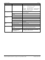
14
14-05-05 netANALYZER
Rev. 1.5.x.x,
NANL-C500RE Rev. 4,
NANL-B500ERE Rev. 3,
NANL-B500GRE Rev. 4
1.1.2,
Section Note on Hardware, Firmware, Driver and Software Versions:
- NANL-B500G-RE: hardware revision 4 added,
- Change of names for
„netANALYZER Remote Access Windows Client.exe“, „netANALYZER
- netSCOPE Driver x86.msi“ und
„netANALYZER - netSCOPE Driver x64.msi“.
- Information about NANL-B500G-RE firmware update added,
- Name of the firmware file NANL-500.nxf updated.
Section Contents of the Product DVD information about NANL-B500GRE firmware update added.
Sections
- Assignment of wrong IP addresses, malfunction (NANL-B500G-RE),
- Notes for Installation and Operation,
- Overview Software and Hardware Installation,
- Assignment of wrong IP addresses, malfunction (NANL-B500G-RE):
Warnings added concerning the assignment of incorrect IP addresses
or malfunction if NANL-B500G-RE is connected incorrectly.
Section Overview how to update Hardware, Software and Driver:
Description for firmware update of the NANL-B500G-RE added.
Section Installation Ethernet Device Configuration (only NANL-B500GRE) updated.
Section Configuration of the IP Address (only NANL-B500G-RE)
requirements added.
Section How to update the NANL-B500G-RE Firmware added.
Adaption of Terminology:
„netANALYZER Driver -> „netANALYZER / netSCOPE Device Driver“,
„netANALYZER Marschaller“ -> „Remote Acces windows Client“.
Chapter Technical Data revised.
1.2,
2.5.6,
4.1,
4.3,
7.2.6,
4.4,
6.2.5,
6.3,
7.8,
13
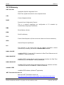
Table 1: List of Revisions
Updates of this document and updates of firmware files are available via
the Hilscher homepage: http://www.hilscher.com/support_downloads.html.
netANALYZER | Installation, Operation and Hardware Description
DOC091110UM14EN | Revision 14 | English | 2014-05 | Released | Public
© Hilscher, 2007-2014
Introduction
1.1.2
9/171
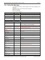
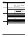
Note on Hardware, Firmware, Driver and Software Versions
Note: The listed revisions of the netANALYZER devices and the versions
of the required driver and software functionally belong together.
Device Name
Device Type
netANALYZER PC Card with PCI Interface for Real-Time Ethernet and
all 100BASE-T Ethernet Networks
NXANL 500-RE
7.310.100
2*
NXANL 500-RE
7.310.100
3*
NANL-C500-RE
7.310.100
4
NANL-B500E-RE
7.311.100
1
NANL-B500E-RE
7.311.100
2
NANL-B500E-RE
7.311.100
3
netANALYZER portable Device with Gigabit Ethernet PC Interface for
Real-Time Ethernet and all 10/100BASE-T Ethernet Networks
NANL-B500G-RE
7.313.100
3
Note: The analyzer device NANL-B500G-RE is only supported by the
netANALYZER software beginning from version 1.5.x.x.
NANL-B500G-RE
7.313.100
4
* Note: If you have already installed the netANALYZER card of the hardware
revision 2 or 3 in your PC, you must apply the netANALYZER hardware update
and then update the driver and the software.
netANALYZER portable Device with ExpressCard Interface for RealTime Ethernet and all 10/100BASE-T Ethernet Networks
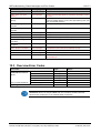
Name
File Name
netANALYZER Hardware Update
netANALYZER_hw_update.iso
Part No.
Revision
Version
Path on the DVD
-
Update NXANL 500RE Revision 3
Version
Path on the DVD
Table 2: netANALYZER Hardware
Name
File Name
Hilscher netANALYZER Setup
netAnalyzer.msi
1.5.x.x
Ethernet Device Configuration Tool
EnDevConfigTool.msi
1.7.x.x
Remote Access Client
(only for Analyzer Device NANL-B500G-RE)
netANALYZER Remote Access
Windows Client.exe
1.5.x.x
Driver
1.5.x.x
Driver\MSI
1.0.2.0
Plugin
1.0.4.0
NANL-B500G-RE
firmware
update\image
V1.0.4.0
netANALYZER
/ netSCOPE
Device Driver
Windows® XP,
®
Windows Vista,
Windows® 7,
®
Windows 8
netANALYZER
Wireshark
Plugin
Hilscher netANALYZER
Wireshark Plugin Setup
WiresharkPlugin.msi
Windows® XP,
Windows® Vista,
®
Windows 7,
Windows® 8
32-Bit
netanalyzer.dll
64-Bit
netanalyzer_x64.dll
(not required for
Wireshark 1.7.1
and newer)
32-Bit
netANALYZER - netSCOPE Driver
x86.msi
64-Bit
netANALYZER - netSCOPE Driver
x64.msi
NANL-B500G-RE firmware update
nanl-b500g-re.update
Software
Table 3: Setup Files for Software Driver and Plugin on the DVD
Name
File Name
Version
Path
netANALYZER Software (Windows-Application)
netANALYZER.exe
1.5.x.x
C:\Program Files\
Hilscher GmbH\
netANALYZER
netANALYZER Firmware
NANL-500.nxf
1.5.x.x
netANALYZER / netSCOPE Device Driver
netANADrv.SYS
1.5.x.x
C:\Program Files\
netANALYZER
Device Driver\...
netANALYZER Toolkit
Table 4: Installed netANALYZER Files (Software Application, Firmware, Driver, Toolkit)
netANALYZER | Installation, Operation and Hardware Description
DOC091110UM14EN | Revision 14 | English | 2014-05 | Released | Public
© Hilscher, 2007-2014
Introduction
1.1.3
10/171
Conventions in this Manual
Notes, operation instructions and results of operation steps are marked as
follows:
Notes
Important: <important note you must follow to avoid malfunction>
Note: <general note>
<note, where to find further information>
Operation Instructions
1.
<instruction>
2.
<instruction>
or
<instruction>
Results
<result>
Safety Messages
The labeling of safety messages is explained in the chapter Safety.
netANALYZER | Installation, Operation and Hardware Description
DOC091110UM14EN | Revision 14 | English | 2014-05 | Released | Public
© Hilscher, 2007-2014
Introduction
1.2
11/171
Contents of the Product DVD
The netANALYZER Installation DVD for the analyzer card NANL-C500-RE
and for the analyzer device NANL-B500E-RE or NANL-B500G-RE
contains:
1.2.1
The netANALYZER setup file
The netANALYZER / netSCOPE Device Driver setup file for 32-bit
and for 64-bit
Firmware update file for Analyzer Device NANL-B500G-RE
The Wireshark netANALYZER Plugin file for 32-bit and for 64-bit (not
required for Wireshark 1.7.1 and newer)
The documentation (netANALYZER User and Driver Manual)
2 Examples for the netANALYZER Application Programming Interface
(API)
Directory Structure of the DVD
Directory Name
Description
Root Directory
Flash Animation (netAnalyzer.exe)
Documentation
Documentation in the Acrobat® Reader Format (PDF),
Adobe Flash Player installation program
Driver
netANALYZER / netSCOPE Device Driver for Windows® XP, Windows® Vista, Windows® 7,
Windows® 8
Remote Access Client (only for Analyzer Device NANL-B500G-RE)
Examples
2 Programming examples for the Application Programming Interface (API) for the analyzer card
NANL-C500-RE and for the analyzer device NANL-B500E-RE or NANL-B500G-RE
fscommand
Help files for the installation program.
NANL-B500G-RE
firmware update
Firmware update file for Analyzer Device NANL-B500G-RE
Plugin
Wireshark netANALYZER Plugin files
Setup
Installer to install the single components (setup.exe)
Software
netANALYZER Setup (netAnalyzer.msi)
Ethernet Device Configuration (EnDevConfigTool.msi)
Update NXANL 500RE Revision 3
netANALYZER hardware update for the NXANL 500-RE-hardware-revisions 2 and 3
Table 5: Directory Structure of the DVD
netANALYZER | Installation, Operation and Hardware Description
DOC091110UM14EN | Revision 14 | English | 2014-05 | Released | Public
© Hilscher, 2007-2014
Introduction
1.2.2
12/171
Documentations netANALYZER
The following documentation overview gives information, for which items
you can find further information in which manual.
Manual
Contents
Document name
Available on the netANALYZER DVD
User Manual netANALYZER
(this document)
Installation, Operation and
Hardware Description
Driver Manual netANALYZER API, Description of the
Windows XP/Vista/7/8, V1.x
netANALYZER API
netANALYZER UM XX EN.pdf
netANALYZER API Windows DRV XX EN.pdf
Ethernet Device Configuration,
Address Setting for Ethernet
capable Hilscher Devices
Operating Instruction Manual Ethernet Device Configuration OI XX EN.pdf
What's New netANALYZER,
netANALYZER DVD
Revision List
What's New netANALYZER DVD RL XX EN.pdf
Available on the Real-Time-Ethernet-Kit DVD, refer to www.hilscher.com
User manual
Real-Time-Ethernet Kit
Analysis Examples
Real-Time-Ethernet-Kit Analysis Examples UM XX
EN.doc
Table 6: Documentations netANALYZER
These documents are available on the DVD delivered with the device
underneath the directory Documentation, in Adobe Acrobat® Reader
format (PDF) or you can download the latest edition of a manual from the
website www.hilscher.com under Support > Downloads > Manuals or
under Products directly with the information about your product.
1.2.3
What's New
All current version information for hardware and software described in this
manual are provided in the folder \Documentation\ What's New
netANALYZER DVD RL XX EN.pdf on the netANALYZER DVD.
netANALYZER | Installation, Operation and Hardware Description
DOC091110UM14EN | Revision 14 | English | 2014-05 | Released | Public
© Hilscher, 2007-2014
Introduction
1.3
1.3.1
13/171
Legal Notes
Copyright
© Hilscher, 2007-2014, Hilscher Gesellschaft für Systemautomation mbH
All rights reserved.
The images, photographs and texts in the accompanying material (user
manual, accompanying texts, documentation, etc.) are protected by
German and international copyright law as well as international trade and
protection provisions. You are not authorized to duplicate these in whole or
in part using technical or mechanical methods (printing, photocopying or
other methods), to manipulate or transfer using electronic systems without
prior written consent. You are not permitted to make changes to copyright
notices, markings, trademarks or ownership declarations. The included
diagrams do not take the patent situation into account. The company
names and product descriptions included in this document may be
trademarks or brands of the respective owners and may be trademarked or
patented. Any form of further use requires the explicit consent of the
respective rights owner.
1.3.2
Important Notes
The user manual, accompanying texts and the documentation were created
for the use of the products by qualified experts, however, errors cannot be
ruled out. For this reason, no guarantee can be made and neither juristic
responsibility for erroneous information nor any liability can be assumed.
Descriptions, accompanying texts and documentation included in the user
manual do not present a guarantee nor any information about proper use
as stipulated in the contract or a warranted feature. It cannot be ruled out
that the user manual, the accompanying texts and the documentation do
not correspond exactly to the described features, standards or other data of
the delivered product. No warranty or guarantee regarding the correctness
or accuracy of the information is assumed.
We reserve the right to change our products and their specification as well
as related user manuals, accompanying texts and documentation at all
times and without advance notice, without obligation to report the change.
Changes will be included in future manuals and do not constitute any
obligations. There is no entitlement to revisions of delivered documents.
The manual delivered with the product applies.
Hilscher Gesellschaft für Systemautomation mbH is not liable under any
circumstances for direct, indirect, incidental or follow-on damage or loss of
earnings resulting from the use of the information contained in this
publication.
netANALYZER | Installation, Operation and Hardware Description
DOC091110UM14EN | Revision 14 | English | 2014-05 | Released | Public
© Hilscher, 2007-2014
Introduction
1.3.3
14/171
Exclusion of Liability
The software was produced and tested with utmost care by Hilscher
Gesellschaft für Systemautomation mbH and is made available as is. No
warranty can be assumed for the performance and flawlessness of the
software for all usage conditions and cases and for the results produced
when utilized by the user. Liability for any damages that may result from the
use of the hardware or software or related documents, is limited to cases of
intent or grossly negligent violation of significant contractual obligations.
Indemnity claims for the violation of significant contractual obligations are
limited to damages that are foreseeable and typical for this type of contract.
It is strictly prohibited to use the software in the following areas:
for military purposes or in weapon systems;
for the design, construction, maintenance or operation of nuclear
facilities;
in air traffic control systems, air traffic or air traffic communication
systems;
in life support systems;
in systems in which failures in the software could lead to personal injury
or injuries leading to death.
We inform you that the software was not developed for use in dangerous
environments requiring fail-proof control mechanisms. Use of the software
in such an environment occurs at your own risk. No liability is assumed for
damages or losses due to unauthorized use.
1.3.4
Warranty
Although the hardware and software was developed with utmost care and
tested intensively, Hilscher Gesellschaft für Systemautomation mbH does
not guarantee its suitability for any purpose not confirmed in writing. It
cannot be guaranteed that the hardware and software will meet your
requirements, that the use of the software operates without interruption and
that the software is free of errors. No guarantee is made regarding
infringements, violations of patents, rights of ownership or the freedom from
interference by third parties. No additional guarantees or assurances are
made regarding marketability, freedom of defect of title, integration or
usability for certain purposes unless they are required in accordance with
the law and cannot be limited. Warranty claims are limited to the right to
claim rectification.
netANALYZER | Installation, Operation and Hardware Description
DOC091110UM14EN | Revision 14 | English | 2014-05 | Released | Public
© Hilscher, 2007-2014
Introduction
1.3.5
15/171
Export Regulations
The delivered product (including the technical data) is subject to export or
import laws as well as the associated regulations of different counters, in
particular those of Germany and the USA. The software may not be
exported to countries where this is prohibited by the United States Export
Administration Act and its additional provisions. You are obligated to
comply with the regulations at your personal responsibility. We wish to
inform you that you may require permission from state authorities to export,
re-export or import the product.
1.3.6
Registered Trademarks
Windows® XP, Windows® Vista, Windows® 7 and Windows® 8 are
registered trademarks of Microsoft Corporation.
Wireshark® and the "fin" logo are a registered trademark of Gerald Combs.
Adobe-Acrobat® is a registered trademark of the Adobe Systems
Incorporated.
PCI™, PCI EXPRESS® und PCIe® are trademarks or registered trademarks
of the Peripheral Component Interconnect Special Interest Group (PCISIG).
All other mentioned trademarks are property of their respective legal
owners.
1.3.7
Obligation to read and understand the Manual
Important!
To avoid personal injury and to avoid property damage to your system
or to your device, you must read and understand all instructions in the
manual and all accompanying texts to your PC card, before installing
and operating your device.
First read the Safety Instructions in the Safety chapter.
Obey to all Safety Messages in the manual.
Keep the product DVD providing the product manuals.
1.3.8
Hilscher Software License Agreement
When you install the Hilscher software you are asked to read the Hilscher
Software License Agreement and explain your acceptance to it.
netANALYZER | Installation, Operation and Hardware Description
DOC091110UM14EN | Revision 14 | English | 2014-05 | Released | Public
© Hilscher, 2007-2014
Safety
2
2.1
16/171
Safety
General Note
The documentation in the form of a user manual, an operating instruction
manual or other manual types, as well as the accompanying texts have
been created for the use of the products by educated personnel. When
using the products, all Safety Messages, Safety Messages, Property
Damage Messages and all valid legal regulations have to be obeyed.
Technical knowledge is presumed. The user has to assure that all legal
regulations are obeyed.
2.2
Intended Use
The netANALYZER devices described in this User Manual each work as a
passive Ethernet analyzer in RT-Ethernet systems. The analyzer card
NANL-C500-RE and the analyzer device NANL-B500E-RE or NANLB500G-RE analyze the data in a communication link and capture the
incoming Ethernet frames.
Device Name
Device Type
netANALYZER PC Card with PCI interface for Real-Time Ethernet and all 100BASE-T
Ethernet networks
NANL-C500-RE
netANALYZER portable Device with ExpressCard interface for Real-Time Ethernet and NANL-B500E-RE
all 10/100BASE-T Ethernet networks
netANALYZER portable Device with Gigabit Ethernet PC interface for Real-Time
Ethernet and all 10/100BASE-T Ethernet networks
NANL-B500G-RE
Table 7: netANALYZER Devices
If the analyzer card NANL-C500-RE and the analyzer device NANL-B500ERE or NANL-B500G-RE are used outside of the scope described in this
user manual respectively in the other netANALYZER documentations, an
error free function can not be guaranteed.
2.3
Personnel Qualification
The analyzer card NANL-C500-RE and the analyzer device NANL-B500ERE or NANL-B500G-RE must only be installed, configured and removed by
qualified personnel. Job-specific technical skills for people professionally
working with electricity must be present concerning the following topics:
Safety and health at work
Mounting and connecting of electrical equipment
Measurement and Analysis of electrical functions and systems
Evaluation of the safety of electrical systems and equipment
Installing and Configuring IT systems
netANALYZER | Installation, Operation and Hardware Description
DOC091110UM14EN | Revision 14 | English | 2014-05 | Released | Public
© Hilscher, 2007-2014
Safety
2.4
17/171
Safety Instructions to avoid Personal Injury
To ensure your own personal safety and to avoid personal injury, you
necessarily must read, understand and follow the following safety
instructions and safety messages in this manual about danger causing
personal injury, before you install and operate your device.
2.4.1
Electrical Shock Hazard (NANL-C500-RE)
Only NANL-C500-RE:
The danger of a lethal electrical shock caused by parts with more than 50V
may occur if you open the PC cabinet to install the NANL-C500-RE card.
HAZARDOUS VOLTAGE is present inside of the PC or of the connecting device, into which the NANL-C500-RE card is integrated. Strictly
obey to all safety rules provided by the device’s manufacturer in the
documentation!
First disconnect the power plug of the PC or of the connecting device,
before you open the cabinet.
Make sure, that the power supply is off at the PC or at the connecting
device.
Open the PC cabinet and install or remove the NANL-C500-RE card
only after disconnecting power.
An electrical shock is the result of a current flowing through the human
body. The resulting effect depends on the intensity and duration of the
current and on its path through the body. Currents in the range of
approximately ½ mA can cause effects in persons with good health, and
indirectly cause injuries resulting from startle responses. Higher currents
can cause more direct effects, such as burns, muscle spasms, or
ventricular fibrillation.
In dry conditions permanent voltages up to approximately 42.4 V peak or
60 V DC are not considered as dangerous if the contact area is equivalent
to the size of a human hand.
Reference Safety [S2]
netANALYZER | Installation, Operation and Hardware Description
DOC091110UM14EN | Revision 14 | English | 2014-05 | Released | Public
© Hilscher, 2007-2014
Safety
2.5
18/171
Safety Instructions to avoid Property Damage
To avoid property damage respectively device destruction to the device and
to your system, you necessarily must read, understand and follow the
following safety instructions and safety messages in this manual about
danger causing property damage, before you install and operate your
device.
2.5.1
Device Destruction by exceeding allowed Supply Voltage
Devices: NANL-C500-RE, NANL-B500E-RE and NANL-B500G-RE
To avoid destruction to your device due to high supply voltage, you must
observe the following instructions. These instructions apply to all devices
described in this manual.
The device may only be operated with the specified supply voltage. Make
sure that the limits of the allowed range for the supply voltage are not
exceeded. A supply voltage above the upper limit can cause severe
damage to the device! A supply voltage below the lower limit can cause
malfunction of the device. The allowed range for the supply voltage is
defined by the tolerances specified in this manual.
The data on the permissible supply voltage of the devices described in this
manual you find in the Power Supply and Host Interface on page 26.
Only NANL-C500-RE:
The device may not be powered by a 5 V supply voltage! The device may
only be powered by a 3.3 V ±5 % supply voltage.
2.5.2
Device Destruction by exceeding allowed Signaling Voltage
Devices: NANL-C500-RE, NANL-B500E-RE and NANL-B500G-RE
To avoid destruction to your device due to high signaling voltage, you must
observe the following instructions. These instructions apply to all devices
described in this manual.
All I/O signal pins at the device tolerate only the specified signaling
voltage!
Operating the device with a signaling voltage other than the specified
signaling voltage may lead to severe damage to the device!
The data on the permissible signaling voltage of the devices described in
this manual you find in the section Power Supply and Host Interface on
page 26.
netANALYZER | Installation, Operation and Hardware Description
DOC091110UM14EN | Revision 14 | English | 2014-05 | Released | Public
© Hilscher, 2007-2014
Safety
19/171
2.5.3
Device Destruction by exceeding allowed External IO Interface
Output Current
Devices: NANL-C500-RE, NANL-B500E-RE and NANL-B500G-RE
To avoid destruction to your device due to exceeding allowed external IO
interface output current, you must observe the following instructions. These
instructions apply to all devices described in this manual.
During operation of the NANL-C500-RE card, of the NANL-B500E-RE
device or of the NANL-B500G-RE device the specified device specific
maximum values for the output current at the external IO interface I/O
signal pins must not be exceeded.
The netX chip and other components of the NANL-C500-RE card, of the
NANL-B500E-RE device or of the NANL-B500G-RE device can be
damaged if the output current at the external IO interface I/O signal pins
exceeds the maximum permissible value!
The data on the maximum permissible output current at the I/O signal pins
for the devices described in this manual you find in the section Maximum
permissible Output Current (external IO Interface) on page 27.
2.5.4
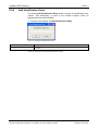
Damage of externally attached Hardware
NANL-C500-RE, NANL-B500E-RE
If the +3.3V output of the external IO interface is enabled, externally
attached hardware could be damaged as voltage is driven.
Before an external device is connected to the NANL-C500-RE card or
the NANL-B500E-RE device, check that the external device is suitable
for the application.
NANL-B500G-RE
If the +3.3V output of the external IO interface is enabled (IO status
LED lights up orange), externally attached hardware could be damaged
as voltage is driven.
If the +24V output of the external IO interface is enabled (IO status LED
lights up red), externally attached hardware could be damaged as
voltage is driven.
Before an external device is connected to the NANL B500G device,
check whether the value for the voltage for the NANL B500G device set
in the netANALYZER software is correct. Furthermore, check whether
the external device is suitable for the application.
netANALYZER | Installation, Operation and Hardware Description
DOC091110UM14EN | Revision 14 | English | 2014-05 | Released | Public
© Hilscher, 2007-2014
Safety
2.5.5
20/171
Electrostatically sensitive Devices (NANL-C500-RE)
Only NANL-C500-RE:
This equipment is sensitive to electrostatic discharge, which cause internal
damage and affect normal operation. Therefore adhere to the necessary
safety precautions for components that are vulnerable with electrostatic
discharge if you install or replace your device. Follow the guidelines listed
hereafter when you handle this equipment:
Touch a grounded object to discharge potential static.
Wear an approved grounding wriststrap.
Do not touch connectors or pins on the device.
Do not touch circuit components inside the equipment.
If available, use a static-safe workstation.
When not in use, store the equipment in appropriate static-safe
packaging.
Reference Safety [S3]
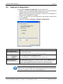
2.5.6
Assignment of wrong IP addresses, malfunction (NANL-B500GRE)
The analyzer device NANL-B500G-RE must not be inserted via a switch or
hub directly into a corporate network with other devices, as long as the
analyzer device is operating in DHCP Server Operation mode. Otherwise,
it may lead to wrong assignment of IP addresses and malfunction.
The analyzer device NANL-B500G-RE works by default as an external
DHCP server in the DHCP Server Operation mode independently and
assigns IP addresses to other devices. This may happen also to devices
which are not concerned by the netANALYZER measurements.
In order to connect the analyzer device NANL-B500G-RE to any network
ensure that DHCP Server Operation mode is disabled.
netANALYZER | Installation, Operation and Hardware Description
DOC091110UM14EN | Revision 14 | English | 2014-05 | Released | Public
© Hilscher, 2007-2014
Safety
21/171
2.6
Labeling of Safety Messages
The Section Safety Messages at the beginning of a chapter are
pinpointed particularly and highlighted by a signal word according to the
degree of endangerment. The kind of danger is specified exactly by the
safety message text and optionally by a specific safety sign.
The Integrated Safety Messages within an instruction description are
highlighted with a signal word according to the degree of endangerment.
The kind of danger is specified exactly by the safety message text.
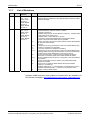
Signal Word
Safety Sign
Meaning (international)
Meaning (USA)
Indicates a direct hazard with high risk, which
will have as consequence death or grievous
bodily harm if it isn't avoided.
Indicates a Hazardous Situation Which if not
Avoided, will Result in Death or Serious Injury.
Indicates a possible hazard with medium risk,
which will have as consequence death or
(grievous) bodily harm if it isn't avoided.
Indicates a Hazardous Situation Which if not
Avoided, could Result in Death or Serious
Injury.
Indicates a minor hazard with medium risk,
which could have as consequence simple
battery if it isn't avoided.
Indicates a Hazardous Situation Which if not
Avoided, may Result in Minor or Moderate
Injury.
USA
Sort of Warning or Principle
Warning of Lethal Electrical Shock
Principle: Disconnect the Power Plug
Table 8: Signal Words and Safety Signa in Safety Messages on Personal Injury
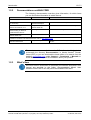
Signal Word
Meaning (international and USA)
Indicates a Property Damage Message.
Safety Sign
Sort of Warning or Principle
Warning on Damages by Electrostatic Discharge
-
Example: Warning on Device Destruction due by too high supply voltage
Table 9: Signal Words and Safety Signa in Safety Messages on Property Damage
In this document all Safety Instructions and Safety Messages are designed
according both to the international used safety conventions as well as to
the ANSI Z535.6 standard, refer to reference safety [S1].
2.7
References Safety
[S1]
ANSI Z535.6-2006 American National Standard for Product Safety Information in
Product Manuals, Instructions, and Other Collateral Materials
[S2]
IEC 60950-1, Information technology equipment - Safety - Part 1: General
requirements, (IEC 60950-1:2005, modified); German Edition EN 60950-1:2006
[S3]
EN 61340-5-1 and EN 61340-5-2 as well as IEC 61340-5-1 and IEC 61340-5-2
netANALYZER | Installation, Operation and Hardware Description
DOC091110UM14EN | Revision 14 | English | 2014-05 | Released | Public
© Hilscher, 2007-2014
Description and Requirements
3
3.1
22/171
Description and Requirements
Introduction to the netANALYZER
You can use the analyzer card NANL-C500-RE or the analyzer device
NANL-B500E-RE or NANL-B500G-RE to record the performance and the
functions of individual systems or system components of bus systems,
which conform to the Ethernet II IEEE 802.3 specification.
The analyzer card NANL-C500-RE and the analyzer device NANL-B500ERE or NANL-B500G-RE described in this user manual, act as a passive
Ethernet analyzer in Real-Time Ethernet systems. The NANL-C500-RE
card and the NANL-B500E-RE device or the NANL-B500G-RE device
analyze the data traffic in a communication stretch and protocol the arriving
Ethernet frames.
By use of the netANALYZER software netANALYZER the modes listed
hereafter can be used:
Capture Data Mode
In the Capture Data mode, the data are recorded to the hard disk of the
PC.
For further information refer to section Recording and analyzing Data
Traffic beginning from page 23.
For data capturing two operating modes are provides:
Ethernet Mode (Standard Capturing)
In the Ethernet Mode standard Ethernet telegrams are captured.
Transparent Mode
In the Transparent Mode standard Ethernet telegrams are captured, which
include the preamble and the SFD (=Start of Frame Delimiter).
For further information refer to section Transparent Mode beginning from
page 115.
Timing Analysis Mode
In the Timing Analysis mode, no frame data are stored, only the time
stamp of individual frames are analyzed. No data recording is performed.
For further information refer to section Timing Analysis beginning from
page 116.
Netload Analysis
In the Netload Analysis mode, the netload of the telegrams is analyzed
over the time. The data recording is performed in the background. The
frame data are captured on the hard disk and can be used for further
analysis in Wireshark.
For further information refer to section Netload Analysis beginning from
page 128.
netANALYZER | Installation, Operation and Hardware Description
DOC091110UM14EN | Revision 14 | English | 2014-05 | Released | Public
© Hilscher, 2007-2014
Description and Requirements
3.1.1
23/171
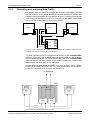
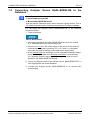
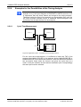
Recording and analyzing Data Traffic
For devices with two Ethernet channels the analyzer card NANL-C500-RE
and the analyzer device NANL-B500E-RE or NANL-B500G-RE capture the
Ethernet frames and adds the time stamps to them. Therefore the analyzer
card or the analyzer device must be connected over two patch cables from
one of the TAP to the Ethernet device connections.
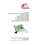
Device 1
Ethernet
Device 2
Device 3
Ethernet
Ethernet
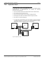
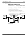
NANL-C500-RE /
NANL-B500E-RE /
NANL-B500G-RE
Ethernet
TAP B
Ethernet
TAP A
Ethernet
Figure 1: Typical Application (Use Case 2) - The communication between a device and its
connection partners in a network should be analyzed
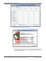
The data capturing must be configured and started via the netANALYZER
software. This way the analyzer card NANL-C500-RE or the analyzer
device NANL-B500E-RE or NANL-B500G-RE and the netANALYZER
software capture the data packets of the communication line, transmit the
data packets and save them on the hard disk.
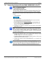
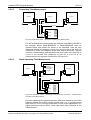
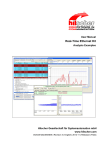
On the analyzer card NANL-C500-RE or at the analyzer device NANLB500E-RE or NANL-B500G-RE two TAP (Test Access Point) are integrated
so that two communication channels are operational.
to Analyzer
TAP
B/A
Ethernet
Device A
1/2
3/6
A/B
Ethernet
Device B
1/2
3/6
RJ45
Port
RJ45
Port
1/2
3/6
RJ45
Port0
1/2
3/6
RJ45
Port1
Figure 2: Example representation physical TAP
netANALYZER | Installation, Operation and Hardware Description
DOC091110UM14EN | Revision 14 | English | 2014-05 | Released | Public
© Hilscher, 2007-2014
Description and Requirements
24/171
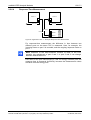
In combination with the driver and the firmware the analyzer card NANLC500-RE or the analyzer device NANL-B500E-RE or NANL-B500G-RE
store the data via DMA on the hard disk of the PC. There the
netANALYZER software then converts the stored binary files (*.hea) in the
open WinPcap format (*.pcap), which can be analyzed e. g. with Wireshark.
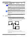
4x IO Lines
Ethernet
Device(s) with digital Outputs
Ethernet
Ethernet
NANL-C500-RE Card,
NANL-B500E-RE Box
or NANL-B500E-RE Box
with integrated TAPs
and IO Event Capture
Hard Disk Drive
Analysis with Wireshark
Figure 3: Typical Analyzer Application with the Capturing of the Ethernet Data Transfer and
IO Events
Additionally, events of up to four digital inputs can be captured. At the four
digital inputs the input signals produce a special Ethernet frame in the
analyzer card NANL-C500-RE or the analyzer device NANL-B500E-RE or
NANL-B500G-RE. This frame is not on the line, but is created for
evaluation purposes.
Note: For the GPIO events in Wireshark a pseudo Ethernet frame is
shown (MAC Address 00:02: A2: FF: FF: FF, Ether Type = 0x88ff), this is
not a true Ethernet frame, but is inserted as wildcard in the firmware. Then
this frame is decoded as GPIO event e. g. with Wireshark.
netANALYZER | Installation, Operation and Hardware Description
DOC091110UM14EN | Revision 14 | English | 2014-05 | Released | Public
© Hilscher, 2007-2014
Description and Requirements
3.2
3.2.1
25/171
System Requirements
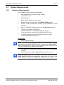
Hardware Requirements
PC or Notebook with the following specification:
Intel compatible CPU, approx. 2 GHz or faster
1 GB RAM or more
DVD ROM drive
SVGA 1024x768 16bit colors or better
20 MB free hard drive space for die netANALYZER software
At least 1 GB free hard disk memory (NTFS partitions) for data
capturing
Approx. 73 MB free hard disk memory for the Wireshark software
1 PCI slot* for NANL-C500-RE card
(*Supply Voltage 3.3 V, Signaling Voltage 5 V or 3.3 V)
1 ExpressCard Slot (notebook) for NANL-B500E-RE device
1 separate network card with RJ45 Ethernet socket (1 Gb/s)
(only for NANL-B500G-RE device)
Accessories:
2 patch cable (Ethernet)
Note: The maximum allowed total length of the Ethernet cable via which
the analyzer card NANL-C500-RE or the analyzer device NANL-B500ERE or NANL-B500G-RE within the Ethernet system are connected via a
TAP to the devices in the system is 100 meters.
The maximum allowed cable length for the 24V power supply is
3 meters.
Power supply unit for NANL-B500G-RE device: 24V dc/ 1.3A
Note: The power supply unit (for standard applications) delivered with the
NANL-B500G-RE device is designed as follows: 24V dc, 1.25A (1.8M
KAB). See also section Power Supply and Host Interface on page 26.
netANALYZER | Installation, Operation and Hardware Description
DOC091110UM14EN | Revision 14 | English | 2014-05 | Released | Public
© Hilscher, 2007-2014
Description and Requirements
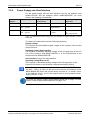
3.2.2
26/171
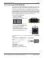
Power Supply and Host Interface
For the power supply and the host interface used for the analyzer card
NANL-C500-RE and the analyzer device NANL-B500E-RE you must
observe the following requirements:
netANALYZER
Hardware
Supply Voltage
NANL-C500-RE
+3.3 V dc ±5 % / 800 mA 5 V or 3.3 V
NANL-B500E-RE 24V dc / 180mA / 4.3W,
18V ... 30V DC
NANL-B500E-RE 24V DC / 1,3A / 31.2W,
18V ... 30V DC
Signaling Voltage
Host Interface
PCIe compatible
-
Host Interface
Signaling Voltage
External IO
PCI slot
3.3 V
PCI Express slot
(ExpressCard)
3.3 V
RJ45 Ethernet socket
(1 Gb/s)
3.3 V 1 mA
or
24V / max. 600 mA
Table 10: Requirements Power Supply and Host Interface for NANL-C500-RE or NANLB500E-RE
The data in the table above have the following meaning:
Supply Voltage
The required and permissible supply voltage at the analyzer card and the
analyzer device
Signaling Voltage Host Interface
The required or tolerated signaling voltage at the I/O signal pins at the PCI
bus of the analyzer card NANL-C500-RE or at the ExpressCard of the
analyzer device NANL-B500E-RE.
Host Interface Type of the host interface
Signaling Voltage External IO
The required or tolerated signaling voltage at the I/O signal pins of the
External IO interface of the analyzer card and the analyzer device.
Note: If the power supply unit delivered with the NANL-B500G-RE device
(dc 24V / 1.25 A) is used, at 500 mA at the external IO interface of the
NANL-B500G-RE device the current limiter is turned on. To avoid a reset
of the analyzer device, use for this special case a more powerful power
supply (24V dc / 1.3A).
For more see section Power Supply NANL-B500E-RE on page 143 and
section Power Supply NANL-B500G-RE on page 144.
netANALYZER | Installation, Operation and Hardware Description
DOC091110UM14EN | Revision 14 | English | 2014-05 | Released | Public
© Hilscher, 2007-2014
Description and Requirements
3.2.3
27/171
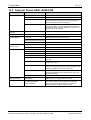
Maximum permissible Output Current (external IO Interface)
NANL-C500-RE and NANL-B500E-RE
For the analyzer card NANL-C500-RE and the analyzer device NANLB500E-RE (all hardware revisions) the maximum permissible output current
for each of the I/O signal pins (pins 1, 3, 5, 7) at the external IO interface is:
10 mA (at 3.3V signaling voltage at the external IO interface).
Device Name
Device Type
Maximum Output Current
at the external IO Interface in [mA]
at 3.3 V Signaling Voltage
Revision
Pin 1
netANALYZER Card PCI RTE
netANALYZER portable
Device PCIe RTE
NXANL 500-RE
Pin 3
Pin 5
Pin 7
2
NXANL 500-RE
3
NANL-C500-RE
4
NANL-B500E-RE
1
NANL-B500E-RE
2
10 mA
10 mA
10 mA
10 mA
Table 11: Maximum permissible Output Current (external IO Interface NANL-C500-RE,
NANL-B500E-RE)
NANL-B500G-RE
For the analyzer device NANL-B500G-RE the maximum permissible output
current at the external IO interface (for all I/O signal pins 1, 3, 5 and 7 in
total) is:
25 mA (at 3.3V signaling voltage at the external IO interface).
600 mA (at 24V signaling voltage at the external IO interface).
Device Name
Device Type
Maximum Output Current
at the external IO Interface in [mA]
at 3.3 V or 24V Signaling Voltage
Revision
For Pin 1, Pin 3, Pin 5 and Pin 7 in total
netANALYZER portable
Device RTE Gigabit
NANL-B500G-RE
2
at 3,3V: 1 mA
NANL-B500G-RE
3
at 24V: 600 mA
NANL-B500G-RE
4
Table 12: Maximum permissible Output Current (external IO Interface NANL-B500G-RE)
netANALYZER | Installation, Operation and Hardware Description
DOC091110UM14EN | Revision 14 | English | 2014-05 | Released | Public
© Hilscher, 2007-2014
Description and Requirements
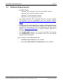
3.3
28/171
Software Requirements
Operating System:
- Windows® XP Professional, SP3, (32-bit and 64-bit Version),
- Windows® Vista, (32-bit and 64-bit Version),
- Windows® 7, (32-bit and 64-bit Version),
- Windows® 8, (32-bit and 64-bit Version).
The program Microsoft .NET Framework Version 2.0 must be installed.
The program can be downloaded from the Internet address:
http://www.microsoft.com/download/en/details.aspx?displaylang=en&id=
16614
In order to show the displayed data, a network monitoring program such
as Wireshark must be installed that supports the WinPcap format.
(Wireshark is "free software"), and can be downloaded from the Internet
address: http://www.wireshark.org/. A special Hilscher Dissector is
integrated in Wireshark.
The netANALYZER software V 1.5.x.x must be installed. This includes
the netANALYZER software, the Analyzer driver and the Analyzer
firmware “Ethernet-Analyzer”.
Only for analyzer device NANL-B500G-RE:
The Remote Access Client must be installed.
The program Ethernet Device Configuration must be installed.
netANALYZER | Installation, Operation and Hardware Description
DOC091110UM14EN | Revision 14 | English | 2014-05 | Released | Public
© Hilscher, 2007-2014
Getting Started
4
4.1
29/171
Getting Started
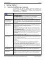
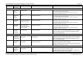
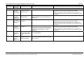
Notes for Installation and Operation
You must read and obey the following notes about installation and
operation of your analyzer card NANL-C500-RE or your analyzer device
NANL-B500E-RE or NANL-B500G-RE to guarantee proper installation and
an error-free operation of your device.
Description
Note
Installation Sequence
The installation sequence:
1. Install Software from DVD.
2. Mount NANL-C500-RE or connect NANL-B500E-RE or NANL-B500G-RE.
must be obeyed. Otherwise the result could be incorrect entries in the Registry. This again
leads to malfunctions during later installation of software updates.
Optimum Operation if
view Participants at PCI
or PCI Express Bus
The capturing feature of the NANL-C500-RE card or the NANL-B500E-RE device works
under heavy load optimally only if the number of participants in the communications PCI
bus or PCI Express bus is minimized. It is advantageous when the NANL-C500-RE card is
the only PCI card in the PC or when the NANL-B500E-RE device is the only ExpressCard
at the notebook.
Inserting netANALYZER
Hardware into the
Communication Link
To analyze the data transfer of a communication line between two devices, these devices
must be connected to the same TAP (Test Access Port). The bandwidth of the network
connection between the NANL-B500G-RE device and the PC must be sufficiently large to
transport the resulting data of the four capturing interfaces.
NANL-B500G-RE:
Important!° The analyzer device NANL-B500G-RE must not be inserted via a switch or
hub directly into a corporate network with other devices, as long as the analyzer device is
operating in DHCP Server Operation mode. Otherwise, it may lead to wrong assignment
of IP addresses and malfunction.
The analyzer device NANL-B500G-RE works by default as an external DHCP server in the
DHCP Server Operation mode independently and assigns IP addresses to other devices.
This may happen also to devices which are not concerned by the netANALYZER
measurements.
In order to connect the analyzer device NANL-B500G-RE to any network ensure that
DHCP Server Operation mode is disabled.
Damage of externally
attached Hardware
NANL-C500-RE, NANL-B500E-RE:
If the +3.3V output of the external IO interface is enabled, externally attached hardware
could be damaged as voltage is driven.
Before an external device is connected, check that the external device is suitable for the
application.
NANL-B500G-RE:
If the +3.3V output of the external IO interface is enabled (IO status LED lights up
orange), externally attached hardware could be damaged as voltage is driven.
If the +24V output of the external IO interface is enabled (IO status LED lights up red),
externally attached hardware could be damaged as voltage is driven.
Before an external device is connected, check whether the value for the voltage set in
the netANALYZER software is correct. Furthermore, check whether the external device
is suitable for the application.
Do not unplug the
ExpressCard during the
Device Operation
During device operation do not unplug the ExpressCard of the analyzer device NANLB500E-RE from the ExpressCard slot at the Notebook. Otherwiese data capturing is
stopped and an error message is displayed, as the device is not any more detected at the
notebook.
Auto-Crossover and
Port-Switching
Because of the auto-crossover function of most of the RTE systems, the assignment of
port 0 and 1 or port 2 and 3 at the netANALYZER device can change between different
test runs. For more information refer to section Auto-Crossover and Port-Switching on
page 72.
netANALYZER | Installation, Operation and Hardware Description
DOC091110UM14EN | Revision 14 | English | 2014-05 | Released | Public
© Hilscher, 2007-2014
Getting Started
30/171
Description
Note
Transferring
NANL-B500G-RE data
save without loss to the
PC
Important! The color of both LEDs on the Gigabit RJ45 Ethernet socket on the reverse
side of the analyzer device NANL-B500G-RE must be green! If the right LED lights up in
orange, the transmission rate to the PC is less than 1 Gb/s, by consequence insufficient
bandwidth may occur. For more see section LINK-ACT and LINK-1000/LINK100 (Reverse
Side) on page 142.
Saved Ethernet
connection from NANLB500G-RE to the PC
Transmission errors on the host Gigabit interface cable (such as EMC interference or bad
connections) do not cause any data loss. However, to strong interference can lead to a
disconnection.
Table 13: Notes about Installation and Operation
4.2
Notes for Wireshark before V1.7.1
Description
Note
Wireshark
netANALYZER Plugin
(not required for Wireshark 1.7.1 and newer)
Activating Wireshark
GPIO Dissector
(not required for Wireshark 1.7.1 and newer)
For Wireshark 1.7.1 and newer the Wireshark netANALYZER plugin is not required
any more.
Update wireshark to the latest version.
For earlier Wireshark versions already installed before V1.7.1 the Wireshark
netANALYZER plugin must be installed to allow displaying the netANALYZER port number
and error codes for every telegram in Wireshark. For more information refer to section
Wireshark netANALYZER Plugin before Wireshark 1.7.1 on page 156.
For Wireshark versions before V1.7.1 the Wireshark GPIO dissector must be
activated. For more information refer to section Activating GPIO Dissector for Wireshark
before V1.7.1 on page 161.
For Wireshark 1.7.1 and newer activating the Wireshark GPIO dissector is not
any more required.
Table 14: Notes for Wireshark before V1.7.1
netANALYZER | Installation, Operation and Hardware Description
DOC091110UM14EN | Revision 14 | English | 2014-05 | Released | Public
© Hilscher, 2007-2014
Getting Started
4.3
31/171
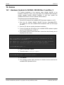
Overview Software and Hardware Installation
Short Description
Detailed Information,
see Chapter / Section
Page
- Install .NET Framework
- Install Wireshark
System Requirements
25
- Insert the netANALYZER DVD.
Software Installation
39
Wireshark
netANALYZER Plugin
before Wireshark 1.7.1
156
Installation Remote
Access Windows Client
(only NANL-B500G-RE)
44
- Install the program Ethernet Device
Configuration.
Installation Ethernet
Device Configuration
(only NANL-B500G-RE)
51
Adhere
- to the Safety Messages on Personal Injury
- and to the Property Damage Messages
given in this manual.
Safety Messages on
Personal Injury,
Property Damage
Messages
60,
2.2 NANL-C500-RE
Mount the analyzer card NANL-C500-RE into a
free PCI slot in the PC.
Mounting Analyzer Card
NANL-C500-RE to the
PC
64
2.3 OR NANL-B500E-RE
Connect the analyzer device NANL-B500E-RE to
the notebook.
NOTICE Connect only one 24 V DC power supply
to the device.
Connecting Analyzer
65
Device NANL-B500E-RE
to the Notebook
2.4 OR NANL-B500G-RE
Connect the analyzer device NANL-B500G-RE to
the RJ45 Ethernet socket (1 Gb/s) at the separate
network card with in the PC.
Connecting Analyzer
66
Device NANL-B500G-RE
to the PC
No
Step
1
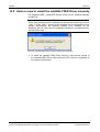
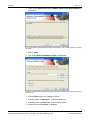
Software Installation
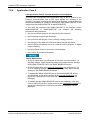
1.1 Requirements
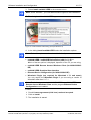
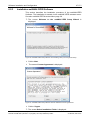
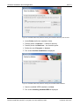
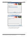
1.2 Install netANALYZER
Software
If the installation program does not start automatically
start the netAnalyzer.msi or Setup.exe program in the
root folder of the DVD.
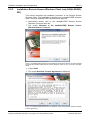
- Run the setup for the netANALYZER software.
- Answer the question netANALYZER optionally
uses the Microsoft .NET 2.0 Framework. Would
you like to install it now? with “No”.
- Install the netANALYZER / netSCOPE Device
Driver and the netANALYZER software.
The netANALYZER Wireshark Plugin is only
required for earlier Wireshark versions already
installed before V1.7.1. Therefore the netANALYZER setup 1.5.x.x contains the plugin installer.
1.3 Only for Analyzer Device - Install the Remote Access Client.
NANL-B500G-RE
1.4
2
Hardware Installation
2.1 Safety Messages
2.5 Inserting Hardware in
the communication link
Note: The RJ45 socket is only for use in
LAN, not for telecommunication circuits.
61
Inserting netANALYZER
Hardware into the
Communication Link
67
Activating GPIO
Dissector for Wireshark
before V1.7.1
161
Performing File Settings
87
Important! The analyzer device NANLB500G-RE must not be inserted via a
switch or hub directly into a corporate
network with other devices, as long as
the analyzer device is operating in
DHCP Server Operation mode.
Insert the NANL-C500-RE card or the NANLB500E-RE or NANL-B500G-RE device into the
communication link to be analyzed.
Activate Wireshark GPIO Dissector.
2.6 Wireshark GPIO
Dissector (not required
for Wireshark V1.7.1 and
higher)
2.7 File Settings
Set file name and capturing path for the capturing
process.
Table 15: Overview Software and Hardware Installation
netANALYZER | Installation, Operation and Hardware Description
DOC091110UM14EN | Revision 14 | English | 2014-05 | Released | Public
© Hilscher, 2007-2014
Getting Started
4.4
32/171
Overview how to update Hardware, Software and Driver
No
Step
Short Description
1.
Hardware Update
Only for existing hardware installation for NXANL
500-RE Rev 2 und Rev 3:
Apply the netANALYZER hardware update and
then update the driver and the software.
2
Detailed Information,
Page
see the Documentation
/ Chapter / Section
Hardware Update for
NXANL 500-RE Rev 2
and Rev 3
153
Update Driver,
Software and Plugin
2.1 Uninstall earlier Versions
of the netANALYZER
Software or of the
netANALYZER Device
Driver
- For Windows 7 select Start > Control Panel >
Uninstall a program.
- In the Uninstall or change a program window
select the netANALYZER or the netANALYZER
Device Driver via the right mouse button, select
the Uninstall entry and remove the software or the
dirver.
2.2 Uninstall earlier Plugins
If so uninstall earlier netANALYZER Wireshark
Plugin version.
Uninstalling manually
installed Plugin
156
2.3 Install latest
netANALYZER
Software
- Insert the current netANALYZER DVD to the
DVD drive
- Run the setup for the netANALYZER software.
- Install the netANALYZER / netSCOPE Device
Driver and the netANALYZER software.
The netANALYZER Wireshark Plugin is only
required for earlier Wireshark versions already
installed before V1.7.1
How to install the
netANALYZER Driver
and Software
40
Wireshark
netANALYZER Plugin
before Wireshark 1.7.1
156
How to update the
NANL-B500G-RE
Firmware
73
2.4 Update the NANLB500G-RE Firmware
Note: The IP addresse of the device and
the IP address of the PC must be in the
same network respectively the DHCP
server must be online.
- Find out the IP address of the device by using the
Ethernet Device Configuration program,.
- Enter the found IP address in the address bar of
Windows Explorer.
- Enter the user name "update" and the password
"nanl-b500g-re" into the FTP server log on screen.
- Copy the firmware update file from the
netANALYZER DVD into the netANALYZER FTP
server directory.
3
Restart PC
To run the netANALYZER software properly you
must restart your PC.
4
Complete Driver
Installation
After you restarted the PC the Found New
Hardware Wizard is started.
- Select No, not this time and click Next.
- Select Install from a list or specific location
(Advanced) and click Next.
- Select Don’t search. I will choose the driver to
install. and click Next.
- Select the netANALYZER / netSCOPE Device
Driver and click Next.
- The wizard installs the software.
Table 16: Overview how to update the netANALYZER Hardware, Software and Driver
netANALYZER | Installation, Operation and Hardware Description
DOC091110UM14EN | Revision 14 | English | 2014-05 | Released | Public
© Hilscher, 2007-2014
Getting Started
4.5
33/171
Overview Settings an Analysis Methods
No
Step
1
Settings
1.1 Starting netANALYZER
Software and selecting
Device
1.2 Selecting Ports and
Analysis Method for
Data Capturing
Short Description
Detailed Information,
Page
see the Documentation
/ Chapter / Section
Start the netANALYZER software and select the
netANALYZER device for data capturing and
analysis.
netANALYZER Software
78
If you have two or more netANALYZER devices
connected to your PC, you can open the
netANALYZER software (beginning with the
version 1.4.x.x) for several devices multiple times
in parallel.
Starting the
netANALYZER Software
multiple Times
78
In the netANALYZER main window, you must set
the Ports to be used for the capturing and which
Analysis Methods are to be used.
netANALYZER Main
Window
83
Performing File Settings
87
GPIO Settings
89
PHY Settings
95
Furthermore you can read here the data about the
captured frames, the found errors, the bus load and
for the capturing time, you can open the window to
convert a binary format files into the WinPcap
format and read the status bar reports on the status
of the application, the firmware or the driver and
the GPIOs (external inputs/outputs).
1.3 Defining Number, Name In the File Settings window you can determine the
and Allocation for Binary number of binary files to be stored, define, that the
Files (*.hea)
capturing data are to be stored to the ring buffer,
define the systematic name of the *.hea files and
where the binary files will be stored.
1.4 GPIO and Trigger
Configuration
In the GPIO Settings window you assign a GPIO
event to every GPIO (external input/output) and
define, how the capturing shall be started or
stopped and a delay time.
1.5 Setting the Transmission Via PHY Settings you can manually set the data
Rate for Port 0 to Port 3 transmission rate per port.
manually
In the Analysis Configuration you define for the
Analysis Configuration
Timing Analysis, whether you will use the
Extended Software Filter Settings and whether
the graph of the analysis data will be displayed as
a Histogram or as a History or as a combined
Histogram and History graph. The Netload Analysis
always used the extended software filters.
106
2.1 Hardware Filter Settings
Selecting analysis data using pre-defined filter
masks or defining own filter masks.
Filter Settings for the
Hardware Filters
91
2.2 Extended Software
Filter Settings
Selecting analysis data using pre-defined filters or
defining own filters.
Extended Software Filter 96
Settings
3.1 Starting Data Capturing
Start the capturing process of the received
Ethernet frames.
Starting Data Capturing
108
3.2 Converting binary Files
into WinPcap Format
Convert binary files *.hea into WinPcap format
*.pcap.
Converting Binary Files
into WinPcap Format
109
1.6 Analysis Configuration
2
3
Filter Settings
Data Capturing
3.3 Displaying Analysis Data Display analysis data of the Ethernet Frames using See help of the used net- e. g. Wireshark.
work monitoring program
4
Timing Analysis
4.1 Presettings
Enter title, select port, configure axis and histogram Timing Analysis
settings.
4.2 Data Evaluation
Measuring value and histogram evaluation.
netANALYZER | Installation, Operation and Hardware Description
DOC091110UM14EN | Revision 14 | English | 2014-05 | Released | Public
116
Extended Software Filter 96
Settings
© Hilscher, 2007-2014
Getting Started
No
Step
5
Netload Analysis
5.1 Analyzing captured
telegrams
34/171
Short Description
Detailed Information,
Page
see the Documentation
/ Chapter / Section
Analyzing the netload of the captured telegrams
over the time and capturing the frame data.
Netload Analysis
128
Table 17: Overview Settings, Filter Settings and Analysis Methods
netANALYZER | Installation, Operation and Hardware Description
DOC091110UM14EN | Revision 14 | English | 2014-05 | Released | Public
© Hilscher, 2007-2014
Device Drawings netANALYZER Hardware
5
35/171
Device Drawings netANALYZER Hardware
5.1
Analyzer Card NANL-C500-RE
2
1
0
Externe EA-Schnittstelle / External IO Interface
(4 digitale Ein-/Ausgänge, 4 digital Inputs/Outputs,
GPIOs 0 - 3)
3
SYS: System LED (gelb/grün) / (yellow/green)
STA 0: Status LED (rot/grün) / (red/green)
STA 1: Status LED (rot/grün) / (red/green)
Ethernet RJ45-Buchse/ Ethernet RJ45 Socket
(4 Ports, 2 Kommunikationskanäle /
4 Ports, 2 Communication Channels)
Kommunikationskanal TAP B /
Communication Channel TAP B
Port 3
Port2
Port 1
LED
grün / green
Pin 7: Term 2
Pin 6: RX-
Port 0
Pin 8: Term 2
Pin 4: Term 1
Pin 5: Term 1
Pin 3: RX+
Pin 1: TX+
Pin 2: TX-
Kommunikationskanal TAP A /
Communication Channel TAP A
LED
gelb / yellow
PCI-Bus / PCI Bus
SYS: System LED (gelb/grün) / (yellow/green)
STA 0: Status LED (rot/grün) / (red/green)
STA 1: Status LED (rot/grün) / (red/green)
STA1
SYS
STA0
GPIO
GND
3
2
1
Externe EA-Schnittstelle / External IO Interface
(4 digitale Ein-/Ausgänge, 4 digital Inputs/Outputs,
GPIOs 0 - 3)
Figure: Top Side
Note: To analyze the data transfer of a
communication line between two
devices, these devices must be
connected to the same TAP (Test
Application Point).
0
Port 3
Ethernet RJ45-Buchse/ Ethernet RJ45 Socket
(4 Ports, 2 Kommunikationskanäle /
4 Ports, 2 Communication Channels)
Kommunikationskanal TAP B /
Communication Channel TAP B
Port 2
Port 1
Kommunikationskanal TAP A /
Communication Channel TAP A
PORT
3 2 1 0
A
B
TAP
Figure: Slot Plate
Port 0
Figure 4: Top Side and Front Plate Analyzer Card NANL-C500-RE
netANALYZER | Installation, Operation and Hardware Description
DOC091110UM14EN | Revision 14 | English | 2014-05 | Released | Public
© Hilscher, 2007-2014
Device Drawings netANALYZER Hardware
5.2
36/171
Analyzer Device NANL-B500E-RE
3
1
2
Figure 5: Overview Analyzer Device NANL-B500E-RE (with ExpressCard)
Analyzer Device NANL-B500E-RE
ExpressCard
ExpressCard Cable
Table 18: Explanations to the Overview NANL-B500E-RE
netANALYZER | Installation, Operation and Hardware Description
DOC091110UM14EN | Revision 14 | English | 2014-05 | Released | Public
© Hilscher, 2007-2014
Device Drawings netANALYZER Hardware
37/171
netANALYZER
External IO
3 2 1 0
TAP B
TAP A
Figure: Front Side
SYS
STA0
STA1
1
Port 3
2
Port 2
3
Port 1
Port 0
POWER
Figure: Reverse Side
+24V
SD
STOP
RUN
RESET
4
DIAG
0V +24V PE
Exress Card
7
5
6
8
9
Figure 6: Front Side and Reverse Side Analyzer Device NANL-B500E-RE
SYS System LED (yellow/green), STA 0, STA1 Status LEDs (red/green)
External IO Interface
External Interface Input/Output Signals with 4 digital Inputs/Outputs (GPIOs 0 to 3)
Ethernet RJ45 Sockets (4 Ports): Port 0 to Port 3, 2 Communication Channels: TAP B, TAP A
Note: To analyze the data transfer of a communication line between two devices, these devices must
be connected to the same TAP (Test Application Point).
Micro SD Card Slot*
Switch* (RUN / STOP / RESET)
Mini B USB Plug* (5-pin)
Cable to ExpressCard
Alternative Female Connector +24V to connect power supply
24V Voltage Supply Combicon: 0V/+24V/PE
* for future use only
Table 19: Explanations to the Front Side and Reverse Side NANL-B500E-RE
netANALYZER | Installation, Operation and Hardware Description
DOC091110UM14EN | Revision 14 | English | 2014-05 | Released | Public
© Hilscher, 2007-2014
Device Drawings netANALYZER Hardware
5.3
38/171
Analyzer Device NANL-B500G-RE
netANALYZER
3
TAP B
External IO
2 1 0
Port 3
TAP A
Port 2
Port 1
Port 0
Figure: Front Side
I/O
SYS
STA0
STA1
1
REC
2
3
Figure: Reverse Side
+24V
UPLINK
1Gb/s
GND +24V FE
5
4
ON
6
OFF
7
USB
LINK-ACT
8
LINK-1000 /
LINK-100
9
Figure 7: Front Side and Reverse Side Analyzer Device NANL-B500G-RE
SYS System LED (yellow/green), STA 0, STA1 Status LEDs (red/green) , IO Status-LED (red/green)
External IO Interface
External Interface Input/Output Signals with 4 digital Inputs/Outputs (GPIOs 0 to 3)
Ethernet RJ45 Sockets (4 Ports): Port 0 to Port 3, 2 Communication Channels: TAP B, TAP A
Note: To analyze the data transfer of a communication line between two devices, these devices must
be connected to the same TAP (Test Application Point).
REC: Button to enable data recording* (Additional function: Restores the default setting for the IP address of your device
(DHCP server mode) - While turning on your device press the REC button for about minute.)
Alternative Female Connector +24V to connect power supply
24V Voltage Supply Combicon: GND/+24V/FE
Power Switch (ON / OFF)
Gigabit Ethernet RJ45 Socket to the PC (1 Port with 1 Gb/s)
USB Plug* (Typ A, 4-pin)
* for future use only
Table 20: Explanations to the Front Side and Reverse Side NANL-B500G-RE
netANALYZER | Installation, Operation and Hardware Description
DOC091110UM14EN | Revision 14 | English | 2014-05 | Released | Public
© Hilscher, 2007-2014
Software Installation and Configuration
6
6.1
39/171
Software Installation and Configuration
netANALYZER Autostart Menu
For the software installation for your netANALYZER device the netANALYZER DVD provides the netANALYZER / netSCOPE Device Driver, the
netANALYZER Software, documentations and programming examples.
Autostart Menu of the netANALYZER DVD
In the autostart menu you can select:
Figure 8: Autostart Menu of the netANALYZER Installation DVD
Driver, Software and Plugin
If you select Install netANALYZER in the Autostart Menu, then you can
select in the subsequent dialog:
For 32-Bit
netANALYZER / netSCOPE Device Driver (x86)
netANALYZER Graphical User Interface
Wireshark Plugin (not required for Wireshark 1.7.1 and newer)
For 64-Bit
netANALYZER / netSCOPE Device Driver (x64)
netANALYZER Graphical User Interface
Wireshark Plugin (not required for Wireshark 1.7.1 and newer)
Firmware Update (only NANL-B500G-RE)
Information to this question you find in section How to update the NANLB500G-RE Firmware on page 73.
Documentation and Examples
Via the autostart menu you can also access to:
The documentation (netANALYZER User and Driver Manual)
2 Examples for the netANALYZER Application Programming Interface
(API)
netANALYZER | Installation, Operation and Hardware Description
DOC091110UM14EN | Revision 14 | English | 2014-05 | Released | Public
© Hilscher, 2007-2014
Software Installation and Configuration
6.2
40/171
How to install the netANALYZER Driver and Software
Important! Before installing the netANALYZER / netSCOPE Device Driver
or before installing the software any existing old driver versions must be
uninstalled.
To install the driver or the software proceed as described hereafter:
1. Close all programs!
2. Enter the netANALYZER Installation DVD in the local DVD ROM drive.
The start screen of the autostart menu is displayed with the following
options:
Figure 9: Autostart Menu netANALYZER Installation DVD
netANALYZER | Installation, Operation and Hardware Description
DOC091110UM14EN | Revision 14 | English | 2014-05 | Released | Public
© Hilscher, 2007-2014
Software Installation and Configuration
41/171
3. Select Install netANALYZER in the autostart menu.
Note: Under Windows® you need administration rights for the installation!
The dialog Install netANALYZER appears.
Figure 10: Install netANALYZER Dialog (Example Windows 7)
4. In the dialog Install netANALYZER select the installation options:
Note: Each of the options can be selected individually.
netANALYZER / netSCOPE Device Driver (x86) for 32-Bit or
netANALYZER / netSCOPE Device Driver (x64) for 64-Bit
Which of the two options is displayed, depends on the PC you are using.
netANALYZER Remote Access Windows Client (for NANL-B500GRE)
netANALYZER Graphical User Interface
Ethernet Device Configuration (for NANL-B500G-RE)
Wireshark Plugin (not required for Wireshark 1.7.1 and newer)
You only require the Wireshark Plugin if you are using a version of
Wireshark older than V1.7.1.
Note: For the Analyzer device NANL-B500G-RE the netANALYZER
Remote Access Windows Client and the program Ethernet Device
Configuration must installed.
Further:
Check License agreement (click here) read and accepted.
Click on Install.
The installation is started.
netANALYZER | Installation, Operation and Hardware Description
DOC091110UM14EN | Revision 14 | English | 2014-05 | Released | Public
© Hilscher, 2007-2014
Software Installation and Configuration
6.2.1
42/171
Installation netANALYZER / netSCOPE Device Driver
This section describes the installation procedure of the netANALYZER /
netSCOPE Device Driver.
Start the installation via the netANALYZER autostart menu. See also
netANALYZER Autostart Menu page 39.
The netANALYZER / netSCOPE Device Driver Setup Wizard opens.
The screen Please read the netANALYZER / netSCOPE Device
Driver License Agreement is displayed:
Figure 11: Hilscher Software License Agreement
Check I accept the terms in the License Agreement.
Start the netANALYZER / netSCOPE Device Driver Installation via
Install.
The screen Installing netANALYZER / netSCOPE Device Driver is
displayed:
Figure 12: netANALYZER / netSCOPE Device Driver Installation
netANALYZER | Installation, Operation and Hardware Description
DOC091110UM14EN | Revision 14 | English | 2014-05 | Released | Public
© Hilscher, 2007-2014
Software Installation and Configuration
43/171
The screen Completed the netANALYZER / netSCOPE Device
Driver Setup Wizard is displayed:
Figure 13: Finishing the netANALYZER / netSCOPE Device Driver Installation
Finish the netANALYZER / netSCOPE Device Driver Installation via
Finish.
The netANALYZER / netSCOPE Device Driver Installation is complete.
For information on how to handle the manual installation of the driver refer
to section Hints on how to install the netANALYZER Driver manually on
page 155.
netANALYZER | Installation, Operation and Hardware Description
DOC091110UM14EN | Revision 14 | English | 2014-05 | Released | Public
© Hilscher, 2007-2014
Software Installation and Configuration
6.2.2
44/171
Installation Remote Access Windows Client (only NANL-B500GRE)
This section describes the installation procedure of the Remote Access
Windows Client. The Installation is started via the netANALYZER autostart
menu. See also netANALYZER Autostart Menu page 39.
Alternatively double click on the netANALYZER Remote Access
Windows Client.exe setup file.
The screen Welcome to the netANALYZER Remote Access
Windows Client is displayed:
Figure 14: netANALYZER Remote Access Windows Client Setup Wizard: The Setup Wizard
will install the netANALYZER Remote Access Windows Client on your computer. (Example
64bit)
Click to Next.
The screen End-User License Agreement is displayed:
Figure 15: netANALYZER Remote Access Windows Client Setup Wizard: Hilscher Software
License Agreement
netANALYZER | Installation, Operation and Hardware Description
DOC091110UM14EN | Revision 14 | English | 2014-05 | Released | Public
© Hilscher, 2007-2014
Software Installation and Configuration
45/171
Check I accept terms in the License Agreement.
The screen Destination Folder is displayed:
Figure 16: netANALYZER Remote Access Windows Client Setup Wizard: Defining the
Installation Directory
Under Install netANALYZER Remote Access Windows Client to
define the installation folder.
Possibly select via Change… a different directory.
The screen Ready to install netANALYZER Remote Access
Windows Client is displayed:
Figure 17: netANALYZER Remote Access Windows Client Setup Wizard: Starting the
netANALYZER Remote Access Windows Client Installation
The screen Installing netANALYZER Remote Access Windows
Client is displayed:
netANALYZER | Installation, Operation and Hardware Description
DOC091110UM14EN | Revision 14 | English | 2014-05 | Released | Public
© Hilscher, 2007-2014
Software Installation and Configuration
46/171
Figure 18: netANALYZER Remote Access Windows Client Setup Wizard: netANALYZER
Remote Access Windows Client Installation
The screen Complete the netANALYZER Remote Access Windows
Client Setup Wizard is displayed:
Figure 19: netANALYZER Remote Access Windows Client Setup Wizard: Finish
netANALYZER Remote Access Windows Client Installation
Close the netANALYZER Remote Access Windows Client installation
via Finish.
The netANALYZER Remote Access Windows Client installation is
complete.
netANALYZER | Installation, Operation and Hardware Description
DOC091110UM14EN | Revision 14 | English | 2014-05 | Released | Public
© Hilscher, 2007-2014
Software Installation and Configuration
6.2.3
47/171
Installation netANALYZER Software
This section describes the installation procedure of the netANALYZER
Software. The Installation is started via the netANALYZER autostart menu.
See also netANALYZER Autostart Menu page 39.
The screen Welcome to the netANALYZER Setup Wizard is
displayed:
Figure 20: netANALYZER Setup Wizard: The Installer guides you through the Setup.
Click to Next.
The screen License Agreement is displayed:
Figure 21: netANALYZER Setup Wizard: Hilscher Software License Agreement
Click to I Agree.
The screen Select Installation Folder is displayed:
netANALYZER | Installation, Operation and Hardware Description
DOC091110UM14EN | Revision 14 | English | 2014-05 | Released | Public
© Hilscher, 2007-2014
Software Installation and Configuration
48/171
Figure 22: netANALYZER Setup Wizard: Defining the Installation Directory and the User
Under Folder define the installation folder.
Possibly select via Browse… a different directory.
Possibly check via Disk Cost… the free disk space.
Define the user: Everyone or Just me.
The screen Confirm Installation is displayed:
Figure 23: netANALYZER Setup Wizard: Starting the netANALYZER Installation
Start the netANALYZER installation via Next.
The screen Installing netANALYZER is displayed:
netANALYZER | Installation, Operation and Hardware Description
DOC091110UM14EN | Revision 14 | English | 2014-05 | Released | Public
© Hilscher, 2007-2014
Software Installation and Configuration
49/171
Figure 24: netANALYZER Setup Wizard: netANALYZER Installation
The screen Installation complete is displayed:
Figure 25: netANALYZER Setup Wizard: Closing the netANALYZER Installation
Close the netANALYZER installation via Close.
The netANALYZER installation is complete.
netANALYZER | Installation, Operation and Hardware Description
DOC091110UM14EN | Revision 14 | English | 2014-05 | Released | Public
© Hilscher, 2007-2014
Software Installation and Configuration
6.2.4
50/171
Default Paths for .hea Files and Software Filters
.hea Files:
The netANALYZER software installation prepares the path:
"My Documents\netANALYZER\hea"
This is the default path for .hea files. After the first usage of the
netANALYZER software, the last used path is the default path. For further
information refer to section Performing File Settings on page 87.
Software Filters:
Upon netANALYZER installation software filter examples are installed to:
"My Documents\netANALYZER\Software Filter"
This is the default path when a filter shall be loaded or saved in the
Extended Software Filter dialog. After the first usage of the netANALYZER software, the last used path is the default path. For further information refer to section Extended Software Filters on page 97.
netANALYZER | Installation, Operation and Hardware Description
DOC091110UM14EN | Revision 14 | English | 2014-05 | Released | Public
© Hilscher, 2007-2014
Software Installation and Configuration
6.2.5
51/171
Installation Ethernet Device Configuration (only NANL-B500GRE)
This section describes the installation procedure of the Ethernet Device
Configuration program. The Installation is started via the netANALYZER
autostart menu. See also netANALYZER Autostart Menu page 39.
Alternatively double click on the EnDevConfigTool.msi setup file.
The screen Welcome to the Ethernet Device Configuration Setup
Wizard is displayed:
Figure 26: Ethernet Device Configuration Setup Wizard: The Setup Wizard will install the
Ethernet Device Configuration on your computer.
Click to Next.
The screen End-User License Agreement is displayed:
Figure 27: Ethernet Device Configuration Setup Wizard: Hilscher Software License
Agreement
netANALYZER | Installation, Operation and Hardware Description
DOC091110UM14EN | Revision 14 | English | 2014-05 | Released | Public
© Hilscher, 2007-2014
Software Installation and Configuration
52/171
Check I accept terms in the License Agreement.
The screen Ready to install Ethernet Device Configuration is
displayed:
Figure 28: Ethernet Device Configuration Setup Wizard: Starting the Ethernet Device
Configuration Installation
The screen Installing Ethernet Device Configuration is displayed:
Figure 29: Ethernet Device Configuration Setup Wizard: Ethernet Device Configuration
Installation
The screen Complete the Ethernet Device Configuration Setup
Wizard is displayed:
netANALYZER | Installation, Operation and Hardware Description
DOC091110UM14EN | Revision 14 | English | 2014-05 | Released | Public
© Hilscher, 2007-2014
Software Installation and Configuration
53/171
Figure 30: Ethernet Device Configuration Setup Wizard: Finish Ethernet Device
Configuration Installation
Close the Ethernet Device Configuration installation via Finish.
The Ethernet Device Configuration installations complete.
For details refer to the Operating Instruction Manual Ethernet Device
Configuration, Address Setting for Ethernet capable Hilscher
Devices. You find this manual on the netANALYZER Installation DVD
under Documentation.
netANALYZER | Installation, Operation and Hardware Description
DOC091110UM14EN | Revision 14 | English | 2014-05 | Released | Public
© Hilscher, 2007-2014
Software Installation and Configuration
6.3
54/171
Configuration of the IP Address (only NANL-B500G-RE)
Requirements: The IP addresse of the device and the IP address of the
PC must be in the same network respectively the DHCP server must be
online.
The NANL-B500G-RE device can operate in three different modes:
Static IP Address (manual assignment)
A fixed IP address is assigned to the analyzer device NANL-B500G-RE.
The user must manually assign the IP address designated.
This option is used only in special cases.
DHCP Client Mode (external DHCP Server required)
The IP address is assigned to the analyzer device NANL-B500GRE.The device gets an IP address from the external DHCP server using
the DHCP protocol. This IP address then automatically is assigned.
This option is used only in special cases.
DHCP Server Operation (device operates as DHCP server)
As an DHCP server, the analyzer device NANL-B500G-RE assigns
itself IP addresses to other devices.
This option is the default setting in the most common use case. The
user must not make any configuration.
Imporant: The analyzer device NANL-B500G-RE must not be inserted via
a switch or hub directly into a corporate network with other devices.
Otherwise, it may lead to wrong assignment of IP addresses and
malfunction. The analyzer device works by default as an external DHCP
server in the DHCP Server Operation mode independently and assigns
IP addresses to other devices. This may happen also to devices which are
not concerned by the netANALYZER measurements.
For the data captured by the analyzer device NANL-B500G-RE and
transmitted over an Ethernet connection to the PC arrive safely, you may
use the analyzer device exclusively with a laptop or a PC with a separate
network card.
DHCP Server Operation
Therefore you must set your LAN connection to (IP V4) Automatically
obtain IP address.
Static IP Address or DHCP Client Operation
To use Static IP Address or DHCP Client Mode, you can configure your
netANALYZER protable device NANL-B500G-RE using the Ethernet
Device Configuration program.
For details refer to the Operating Instruction Manual Ethernet Device
Configuration, Address Setting for Ethernet capable Hilscher
Devices. You find this manual on the netANALYZER Installation DVD
under Documentation.
Note: In case of problems due to incorrect settings of the IP address (e. g.
device is not accessible), restart your device. While turning on your device
press the REC button for about minute. Then the default setting for the IP
address of your device (DHCP server mode) is restored.
netANALYZER | Installation, Operation and Hardware Description
DOC091110UM14EN | Revision 14 | English | 2014-05 | Released | Public
© Hilscher, 2007-2014
Software Installation and Configuration
6.4
55/171
Open Documentation or Examples
Via the autostart menu of the netANALYZER Installation DVD are also the
documentation and programming examples for netANALYZER are available.
Open Documentations Directory
1. Enter the netANALYZER Installation DVD in the local DVD ROM drive.
The start screen of the autostart menu is displayed:
2. Select Open Documentations Directory in the autostart menu.
The folder Documentation is displayed:
Figure 31: Folder „Documentation“ of the netANALYZER Installation DVD
The folder Documentation contains:
The user manual netANALYZER
The folder API with the Driver Manual netANALYZER API, Windows
XP/Vista/7/8, V1.x
Refer also to section Documentations netANALYZER on page 12.
Or:
Open Application Examples Directory
3. Select Open Application Examples Directory in the autostart menu.
The folder Examples is displayed with:
2 programming examples for the application programming interface
(API) the analyzer card NANL-C500-RE and the analyzer device NANLB500E-RE or NANL-B500G-RE.
netANALYZER | Installation, Operation and Hardware Description
DOC091110UM14EN | Revision 14 | English | 2014-05 | Released | Public
© Hilscher, 2007-2014
Software Installation and Configuration
6.5
6.5.1
56/171
Display and Settings in Wireshark
netANALYZER Info Block in extended .pcap File Format
In the extended .pcap file format according to the link-layer type with
wireshark 1.7.1 the compatible "netANALYZER frame info block" with the
additional information is in the 4 bytes ahead of the Ethernet frame.
Figure 32: Wireshark 1.7.1: netANALYZER Info Block in the extended .pcap File Format
Beginning with version 1.4.x.x, the netANALYZER software converts the
recorded data in either
the .pcap file format with the info block behind the Ethernet frame or
into the extended link-layer type .pcap file format with the info block
ahead of the Ethernet frame.
For additional information refer to section Converting Binary Files into
WinPcap Format page 109.
The extended .pcap file format generated by the netANALYZER software
beginning from V1.4.x.x, can only be opened in Wireshark versions
beginning from V1.7.1. When using earlier versions of Wireshark, the error
message "link-layer type is not supported" is displayed.
For troubleshooting, you must either install the latest version of Wireshark
or convert the .pcap file to the .pcap- file format with the info block behind
the Ethernet frame. The .pcap file format with the info block behind the
Ethernet frame, however, will no longer be supported by future versions of
Wireshark.
Real Frame Length
Important: The 4 bytes additional information of the "netANALYZER
Frame Info Block" ahead of the Ethernet frame are not included in the real
frame length.
In the example in Figure 32 72 bytes have been captured, the real frame
length in this example is 68 bytes, however.
netANALYZER | Installation, Operation and Hardware Description
DOC091110UM14EN | Revision 14 | English | 2014-05 | Released | Public
© Hilscher, 2007-2014
Software Installation and Configuration
6.5.2
57/171
Display Port Number in Wireshark Packet List
To display the port information in the protocol tree of Wireshark directly in
the packet list of Wireshark, you can insert a new column to the packet list
of Wireshark. Therefore proceed as follows:
Select in Wireshark Edit > Preferences.
Figure 33: Wireshark: Edit > Preferences
Select in the Preferences dialog at the left side User Interfaces >
Columns.
Figure 34: Wireshark: Preferences > User Interface > Columns
netANALYZER | Installation, Operation and Hardware Description
DOC091110UM14EN | Revision 14 | English | 2014-05 | Released | Public
© Hilscher, 2007-2014
Software Installation and Configuration
58/171
Select under Field Type (1) „Custom“.
Enter for the Field name (2) „netanalyzer.port“.
Click to Add.
The new line „New Column“ is displayed.
Figure 35: Wireshark: Preferences > User Interface > Columns > Add
Enter at Title (3) the heading name “Port”.
Move the line to the requested position.
netANALYZER | Installation, Operation and Hardware Description
DOC091110UM14EN | Revision 14 | English | 2014-05 | Released | Public
© Hilscher, 2007-2014
Software Installation and Configuration
59/171
Figure 36: Wireshark: Preferences > User Interface > Columns
Close the window via OK.
In the packet list of Wireshark the number of the port now is displayed
as an addition column.
Figure 37: Wireshark: Port Number in the Packet List
netANALYZER | Installation, Operation and Hardware Description
DOC091110UM14EN | Revision 14 | English | 2014-05 | Released | Public
© Hilscher, 2007-2014
netANALYZER Hardware Installation
7
60/171
netANALYZER Hardware Installation
To install the NANL-C500-RE card or NANL-B500E-RE or NANL-B500GRE device handle as described in the sections hereafter.
For the installation of the netANALYZER device check any notes in the
overview in chapter Getting Started on page 29.
7.1
Safety Messages on Personal Injury
Obey to the following safety messages on personal injury, when installing,
uninstalling or replacing the NANL-C500-RE card.
7.1.1
Electrical Shock Hazard (NANL-C500-RE)
NANL-C500-RE card:
Lethal Electrical Shock caused by parts with more than 50V!
HAZARDOUS VOLTAGE inside of the PC or of the connecting device.
Strictly obey to all safety rules provided by the device’s manufacturer in
the documentation!
First disconnect the power plug of the PC or of the connecting device,
before you open the cabinet.
Make sure, that the power supply is off at the PC or at the connecting
device.
Open the PC cabinet and install or remove the NANL-C500-RE card
only after disconnecting power.
netANALYZER | Installation, Operation and Hardware Description
DOC091110UM14EN | Revision 14 | English | 2014-05 | Released | Public
© Hilscher, 2007-2014
netANALYZER Hardware Installation
7.2
61/171
Property Damage Messages
Obey to the following property damage messages, when installing the
netANALYZER device (NANL-C500-RE card or NANL-B500E-RE or NANLB500G-RE device).
7.2.1
Device Destruction by exceeding allowed Supply Voltage
Device Destruction!
Use only the permissible supply voltage to operate the netANALYZER
device.
Operating the netANALYZER device with a supply voltage above of the
specified range leads to device destruction.
For detailed information on the supply voltage, refer to section Power
Supply and Host Interface on page 26.
7.2.2
Device Destruction by exceeding allowed Signaling Voltage
Device Destruction!
All I/O signal pins at the netANALYZER device tolerate only the
specified signaling voltage!
Operating the netANALYZER device with a signaling voltage other than
the specified signaling voltage may lead to severe damage to the
netANALYZER device!
For detailed information on the signaling voltage, refer to section Power
Supply and Host Interface on page 26.
7.2.3
Device Destruction by exceeding permissible External IO
Interface Output Current
Device Destruction!
During operation of the NANL-C500-RE card and the NANL-B500E-RE
or NANL-B500G-RE device the specified device specific maximum
values for the output current at the external IO interface I/O signal pins
must not be exceeded.
The netX chip and other components of the NANL-C500-RE card and
the NANL-B500E-RE or NANL-B500G-RE device can be damaged if
the output current at the external IO interface I/O signal pins exceeds
the maximum permissible value!
The data on the maximum permissible output current at the I/O signal pins
for the devices described in this manual you find in the section Maximum
permissible Output Current (external IO Interface) on page 27.
netANALYZER | Installation, Operation and Hardware Description
DOC091110UM14EN | Revision 14 | English | 2014-05 | Released | Public
© Hilscher, 2007-2014
netANALYZER Hardware Installation
7.2.4
62/171
Damage of externally attached Hardware
Damage of externally attached Hardware
NANL-C500-RE, NANL-B500E-RE
If the +3.3V output of the external IO interface is enabled, externally
attached hardware could be damaged as voltage is driven.
Before an external device is connected, check that the external device
is suitable for the application.
NANL-B500G-RE
If the +3.3V output of the external IO interface is enabled (IO status LED
lights up orange), externally attached hardware could be damaged as
voltage is driven.
If the +24V output of the external IO interface is enabled (IO status LED
lights up red), externally attached hardware could be damaged as
voltage is driven.
Before an external device is connected, check whether the value for the
voltage set in the netANALYZER software is correct. Furthermore,
check whether the external device is suitable for the application.
7.2.5
Electrostatically sensitive Devices (NANL-C500-RE)
NANL-C500-RE card:
Adhere to the necessary safety precautions for components that are
vulnerable with electrostatic discharge.
Electrostatically sensitive Devices
To prevent damage to the PC and the NANL-C500-RE, make sure:
that the NANL-C500-RE card is grounded via the endplate and the PC
and make sure,
that you are discharged when you mount/demount the NANL-C500-RE
card.
netANALYZER | Installation, Operation and Hardware Description
DOC091110UM14EN | Revision 14 | English | 2014-05 | Released | Public
© Hilscher, 2007-2014
netANALYZER Hardware Installation
7.2.6
63/171
Assignment of wrong IP addresses, malfunction (NANL-B500GRE)
Imporant: The analyzer device NANL-B500G-RE must not be inserted via
a switch or hub directly into a corporate network with other devices, as
long as the analyzer device is operating in DHCP Server Operation
mode. Otherwise, it may lead to wrong assignment of IP addresses and
malfunction.
The analyzer device NANL-B500G-RE works by default as an external
DHCP server in the DHCP Server Operation mode independently and
assigns IP addresses to other devices. This may happen also to devices
which are not concerned by the netANALYZER measurements.
In order to connect the analyzer device NANL-B500G-RE to any network
ensure that DHCP Server Operation mode is disabled.
netANALYZER | Installation, Operation and Hardware Description
DOC091110UM14EN | Revision 14 | English | 2014-05 | Released | Public
© Hilscher, 2007-2014
netANALYZER Hardware Installation
7.3
64/171
Mounting Analyzer Card NANL-C500-RE to the PC
Note: The installation sequence must be obeyed.
1. Install software from DVD
2. Mount NANL-C500-RE card
Otherwise, there will be incorrect registry entries. This in turn leads to
disturbances in subsequent installation of software updates.
For mounting the analyzer card NANL-C500-RE to the PC handle as
follows:
1. Take safety precautions.
Lethal Electrical Shock caused by parts with more than 50V!
Disconnect the power plug of the PC or of the connecting device.
Make sure, that the power supply is off at the PC or at the connecting
device.
Electrostatically sensitive Devices
Make sure, that the NANL-C500-RE card is grounded via the endplate
and the PC and make sure, that you are discharged when you
install/uninstall the NANL-C500-RE card.
Device Destruction!
Use exclusively 3.3 V for supply voltage to operate the NANL-C500-RE
card. Operation with 5 V supply voltage leads to device destruction.
At the I/O signal pins of the PCI bus use exclusively 5 V or 3.3 V
signaling voltage and at the I/O signal pins of the External IO interface
use exclusively 3.3 V signaling voltage. Higher signaling voltage may
lead to severe damage to the NANL-C500-RE card!
2. Open the cabinet of the PC.
3. Plug in the analyzer card NANL-C500-RE on a free PCI slot.
4. Fix the slot plate of analyzer card NANL-C500-RE to the slot plate of
the PC by using a screw.
5. Close the PC casing.
6. Connect the PC to the power supply and switch on the PC.
netANALYZER | Installation, Operation and Hardware Description
DOC091110UM14EN | Revision 14 | English | 2014-05 | Released | Public
© Hilscher, 2007-2014
netANALYZER Hardware Installation
7.4
65/171
Connecting Analyzer Device NANL-B500E-RE to the
Notebook
Note: The installation sequence:
1. Install software from DVD
2. Mount NANL-B500E-RE device
must be obeyed. Otherwise, there will be incorrect registry entries. This in
turn leads to disturbances in subsequent installation of software updates.
For connecting the analyzer device NANL-B500E-RE to the Notebook
handle as follows:
1. Take precautions.
Device Destruction!
The voltage applied at the NANL-B500E-RE device must not exceed
30 V, otherwise the device may be destroyed.
Connect only one 24 V DC power supply to the device. If the device is
connected to both power connectors (0V/+24V/PE and +24V) simultaneously, this may lead to damage to the used power supply units!
At the ExpressCard use exclusively a PCIe compatible signaling voltage
and at the I/O signal pins of the External IO interface use exclusively
3.3 V signaling voltage. Higher signaling voltage may lead to severe
damage to the NANL-B500E-RE device!
2. Plug in the ExpressCard of the analyzer device NANL-B500E-RE to a
free ExpressCard slot at the Notebook.
3. Connect the analyzer device NANL-B500E-RE to an external 24V
power supply.
netANALYZER | Installation, Operation and Hardware Description
DOC091110UM14EN | Revision 14 | English | 2014-05 | Released | Public
© Hilscher, 2007-2014
netANALYZER Hardware Installation
7.5
66/171
Connecting Analyzer Device NANL-B500G-RE to the PC
Note: The installation sequence:
1. Install software from DVD
2. Mount NANL-B500G-RE device
must be obeyed. Otherwise, there will be incorrect registry entries. This in
turn leads to disturbances in subsequent installation of software updates.
For connecting the analyzer device NANL-B500G-RE to the PC handle as
follows:
1. Take precautions.
Device Destruction!
The voltage applied at the NANL-B500G-RE device must not exceed
30 V, otherwise the device may be destroyed.
At the I/O signal pins of the External IO interface use exclusively 3.3 V
or 24 V signaling voltage. Higher signaling voltage may lead to severe
damage to the NANL-B500G-RE device!
2. Establishing an Ethernet connection from the analyzer device NANLB500G-RE to the PC.
Note: The Ethernet connection from the analyzer device NANL-B500GRE to the PC is a saved connection without loss. Transmission errors on
the host Gigabit interface cable (such as EMC interference or bad
connections) do not cause any data loss. However, to strong interference
can lead to a disconnection.
Connect the Ethernet cable to the Gigabit RJ45 Ethernet socket
UPLINK 1 Gb/s at the reverse side of the device.
Connect the Ethernet cable to the RJ45 Ethernet socket (1 Gb/s) at the
separate network card with in the PC.
3. Connect the analyzer device NANL-B500G-RE to an external 24V
power supply.
Important! The color of both LEDs on the Gigabit RJ45 Ethernet socket
on the reverse side of the analyzer device NANL-B500G-RE must be
green! If the right LED lights up in orange, the transmission rate to the PC
is less than 1 Gb/s, by consequence insufficient bandwidth may occur.
netANALYZER | Installation, Operation and Hardware Description
DOC091110UM14EN | Revision 14 | English | 2014-05 | Released | Public
© Hilscher, 2007-2014
netANALYZER Hardware Installation
7.6
67/171
Inserting
netANALYZER
Communication Link
Hardware
into
the
Imporant: The analyzer device NANL-B500G-RE must not be inserted via
a switch or hub directly into a corporate network with other devices, as
long as the analyzer device is operating in DHCP Server Operation
mode. Otherwise, it may lead to wrong assignment of IP addresses and
malfunction.
Connect the analyzer card NANL-C500-RE or the analyzer device NANLB500E-RE or NANL-B500G-RE via two patch cables with the Ethernet
device connections, in parallel to the communication connection to be
analyzed. Basically, different assemblies are possible.
Notes:
(1) To analyze the data transfer of a communication line between two
devices, these devices must be connected to the same TAP (Test
Application Point).
(2) The RJ45 socket is only for use in LAN, not for telecommunication
circuits.
In the following subsections typical application cases are described.
7.6.1
Application Case 1
Capturing and analyzing the Communication between two Devices
To capture the communication between two Ethernet devices, mount
the analyzer card NANL-C500-RE or the analyzer device NANL-B500ERE or NANL-B500G-RE over Ethernet cables as displayed in the
picture below.
Connect both Ethernet cable only in TAP A (or in TAP B).
Device 1
Device 2
Ethernet
Ethernet
Ethernet
TAP B
TAP A
NANL-C500-RE /
NANL-B500E-RE /
NANL-B500G-RE
Ethernet
Figure 38: Application Case1
Furthermore, it analyzes the number of erroneous messages.
A forwarding time of telegrams by a device can not be determined. See
Application Case 2.
netANALYZER | Installation, Operation and Hardware Description
DOC091110UM14EN | Revision 14 | English | 2014-05 | Released | Public
© Hilscher, 2007-2014
netANALYZER Hardware Installation
7.6.2
68/171
Application Case 2
Application Case 2 is the typical Application Case
In this case the analyzer card NANL-C500-RE or the analyzer device
NANL-B500E-RE or NANL-B500G-RE can analyze the following
procedures and parameters:
the communication between two devices each for two channels each,
the forwarding time through the device,
the cycle time and the jitter in the cyclically running protocols,
the changes of the data in the Ethernet frame through the device,
the number of erroneous telegrams.
To capture the communication of the two channels, mount the analyzer
card NANL-C500-RE or the analyzer device NANL-B500E-RE or NANLB500G-RE via Ethernet cables as shown in the picture.
Device 1
Ethernet
Device 2
Device 3
Ethernet
Ethernet
TAP B
Ethernet
Ethernet
TAP A
NANL-C500-RE /
NANL-B500E-RE /
NANL-B500G-RE
Ethernet
Figure 39: Application Case2
netANALYZER | Installation, Operation and Hardware Description
DOC091110UM14EN | Revision 14 | English | 2014-05 | Released | Public
© Hilscher, 2007-2014
netANALYZER Hardware Installation
7.6.3
69/171
Application Case 3
Like Application Case 2, but with further Devices
This use case corresponds to the application case 2, but with the difference
that further devices are between the two analyzed Ethernet channels.
In this case the analyzer card NANL-C500-RE or the analyzer device
NANL-B500E-RE or NANL-B500G-RE can analyze the following
procedures and parameters:
the communication for two channels,
the forwarding time through several devices,
the cycle time and the jitter in the cyclically running protocols,
the changes of the data in the Ethernet frame through several devices,
the number of erroneous telegrams.
To capture the communication of the two channels, mount the analyzer
card NANL-C500-RE or the analyzer device NANL-B500E-RE or NANLB500G-RE via Ethernet cables as shown in the picture.
Device 1
Ethernet
Device 2
Device 3
Device 4
Ethernet
Ethernet
Ethernet
Ethernet
TAP B
Ethernet
Ethernet
TAP A
NANL-C500-RE /
NANL-B500E-RE /
NANL-B500G-RE
Ethernet
Figure 40: Application Case3
netANALYZER | Installation, Operation and Hardware Description
DOC091110UM14EN | Revision 14 | English | 2014-05 | Released | Public
© Hilscher, 2007-2014
netANALYZER Hardware Installation
7.6.4
70/171
Application Case 4
Like Application Case 2, but with Analysis of Input Signals
This use case corresponds to the application case 2, but in addition to the
Ethernet communication one to four input signals are included in the
analysis. If an edge reversal at the digital input happens, a pseudo Ethernet
frame with timestamp is created in the analyzer card NANL-C500-RE or the
analyzer device NANL-B500E-RE or NANL-B500G-RE.
In this case the analyzer card NANL-C500-RE or the analyzer device
NANL-B500E-RE or NANL-B500G-RE can analyze the following
procedures and parameters:
the communication between two devices for two channels,
the forwarding time through the device,
the cycle time and the jitter in the cyclically running protocols,
the changes of the data in the Ethernet frame through the device,
protocol-stack processing time from Ethernet frame reception to digital
output switching,
the input signal events on the basis of time-stamps,
the number of erroneous telegrams.
Device Destruction!
At the I/O signal pins of the External IO interface use exclusively 3.3 V
signaling voltage. Higher signaling voltage may lead to severe damage
to the NANL-C500-RE card or the NANL-B500E-RE device!
At the I/O signal pins of the external IO interface use exclusively 3.3 V
or 24 V signaling voltage. Higher signaling voltage may lead to severe
damage to the NANL-B500G-RE device!
To operate the NANL-C500-RE card or the NANL-B500E-RE device
use maximally 10 mA output current at the external IO interface I/O
signal pins. Otherwise the netX chip and other components may be
damaged.
To operate the the NANL-B500G-RE device use maximally 1 mA (bei
3,3V) or 600 mA (bei 24V) output current at the external IO interface I/O
signal pins. Otherwise the netX chip and other components may be
damaged.
netANALYZER | Installation, Operation and Hardware Description
DOC091110UM14EN | Revision 14 | English | 2014-05 | Released | Public
© Hilscher, 2007-2014
netANALYZER Hardware Installation
71/171
Damage of externally attached Hardware
NANL-C500-RE, NANL-B500E-RE
If the +3.3V output of the external IO interface is enabled, externally
attached hardware could be damaged as voltage is driven.
Before an external device is connected, check that the external device
is suitable for the application.
NANL-B500G-RE
If the +3.3V output of the external IO interface is enabled (IO status LED
lights up orange), externally attached hardware could be damaged as
voltage is driven.
If the +24V output of the external IO interface is enabled (IO status LED
lights up red), externally attached hardware could be damaged as
voltage is driven.
Before an external device is connected, check whether the value for the
voltage set in the netANALYZER software is correct. Furthermore,
check whether the external device is suitable for the application.
To capture the communication of the two channels, mount the analyzer
card NANL-C500-RE or the analyzer device NANL-B500E-RE via
Ethernet cables as shown in the picture.
The picture also shows schematically how a digital output signal is
connected from the device to the digital input of the analyzer card NANLC500-RE or the analyzer device NANL-B500E-RE.
Device 2
Ethernet Device
with digital
Outputs
Device 1
Device 3
IO Line
Ethernet
Ethernet
Ethernet
3 2
1
0 GPIO
TAP B
Ethernet
Ethernet
TAP A
NANL-C500-RE /
NANL-B500E-RE /
NANL-B500G-RE
Ethernet
Figure 41: Application Case4 – Recording of the Runtime in the Device
netANALYZER | Installation, Operation and Hardware Description
DOC091110UM14EN | Revision 14 | English | 2014-05 | Released | Public
© Hilscher, 2007-2014
netANALYZER Hardware Installation
7.7
72/171
Auto-Crossover and Port-Switching
In a system with for example one netANALYZER device and two RTE
devices, the assignment of port 0 and port 1 or port 2 and port 3 can
change between different test runs. This is due to the auto-crossover
feature of most RTE systems. For auto-crossover the cable assignment by
the devices is given randomly. The assignment of the lines as a
"transmission line" or "receiving line" is random.
Example
Device 1
Device 2
PROFINET IO
PROFINET IO
|________ netANALYZER Device__________|
1. Measurement
2. Measurement
Line A on Port 0
"Transmission Line"
"Receiving Line"
Line B on Port 1
"Receiving Line"
"Transmission Line"
Figure 42: Example - Auto-Crossover and Port-Switching
At the 2nd Measurement in this example the receipt of the telegrams is
wrong. The port numbers in the telegrams were exchanged.
If both devices use auto-crossover, there is the possibility that port 0 and
port 1 will be exchanged for subsequent measurements. This is also true
for port 2 and port 3.
Schematic Design of a TAP
Ports of Device 1 and Device 2 are switched
TX+
TX-
Rx 1
receives,
what was
sent from
Device 1
RX1+ RX1-
RX2+ RX2netX
Two times per netANALYZER device
RX+
RX-
TX+
TX-
TX+
TX-
RX+
RX-
Rx 1
receives,
what was
sent from
Device 2
RX1+ RX1-
Device 2
RX+
RX-
Device 1
netANALYZER TAP
RX+
RX-
Device 2
Device 1
netANALYZER TAP
TX+
TX-
RX2+ RX2netX
Two times per netANALYZER device
Figure 43: Design of a TAP, at the right Side Ports of Device 1 and Device 2 exchanged
The schematic design of a TAP shown in Figure 43 makes evident which
effects an interchange of the lines of the two devices has.
Workaround
A workaround is possible, by drawing conclusions from the records of two
consecutive test runs. In the records for the second test run compared with
the first test run, modified port numbers can be found.
netANALYZER | Installation, Operation and Hardware Description
DOC091110UM14EN | Revision 14 | English | 2014-05 | Released | Public
© Hilscher, 2007-2014
netANALYZER Hardware Installation
7.8
73/171
How to update the NANL-B500G-RE Firmware
Requirements: The IP addresse of the analyzer device NANL-B500G-RE
must be configured according to section Configuration of the IP Address
(only NANL-B500G-RE) on page 54. The IP addresse of the device and
the IP address of the PC must be in the same network respectively the
DHCP server must be online.
Steps
1. Open the Ethernet Device Configuration program.
2. Scan for devices.
Your analyzer device NANL-B500G-RE is displayed.
Figure 44: Ethernet Device Configuration - NANL-B500G-RE found (Example)
3. Obtain the IP address of your NANL-B500G-RE device the firmware of
which you want to update. For the example shown in the figure above
the obtained IP address is 192.168.1.1.
For details to the Ethernet Device Configuration program refer to the
Operating Instruction Manual Ethernet Device Configuration, Address
Setting for Ethernet capable Hilscher Devices.
4. Open the Windows explorer.
5. Enter the IP address obtained from step 3 to the address bar of the
Windows explorer as follows: ftp://[IP addresse].
Alternatively you can use a common FTP utility. Then only enter the IP
addresse [IP addresse].
The Windows explorer Log On As screen appears.
netANALYZER | Installation, Operation and Hardware Description
DOC091110UM14EN | Revision 14 | English | 2014-05 | Released | Public
© Hilscher, 2007-2014
netANALYZER Hardware Installation
74/171
6. On the Windows explorer Log On As screen enter "update" as user
name and "nanl-b500g-re" as password (without the double quotes).
Figure 45: FTP Server Log On Screen
The the netANALYZER FTP server directory opens.
7. Copy the incremental firmware update file nanl-b500g-re.update to the
netANALYZER FTP server directory.
The firmware update file can be found on the netANALYZER DVD in the
diectory NANL-B500G-RE firmware update.
Figure 46: Copy the Firmware update File to the netANALYZER FTP Server Directory.
netANALYZER | Installation, Operation and Hardware Description
DOC091110UM14EN | Revision 14 | English | 2014-05 | Released | Public
© Hilscher, 2007-2014
netANALYZER Hardware Installation
75/171
Once the file is copied the FTP Server directory should contain the file
nanl-b500g-re.update.
Figure 47: netANALYZER FTP Server Directory containing the Firmware update File
There may exist a file update.log from a previous update process, the log
file can be ignored.
8. Power off your NANL-B500G-RE device.
9. Power on your NANL-B500G-RE device and wait until the device is fully
operational (SYS LED = green, STA0 LED = red, STA1 LED = off).
Your device is now updated.
10. To verify if the update process was successfully, verify the version
information.
Open the netANALYZER software and select your device. See also in
section Selecting netANALYZER Device on page 80.
Figure 48: Select Analyzer Device NANL-B500G-RE
The netANALYZER main window opens.
netANALYZER | Installation, Operation and Hardware Description
DOC091110UM14EN | Revision 14 | English | 2014-05 | Released | Public
© Hilscher, 2007-2014
netANALYZER Hardware Installation
76/171
Figure 49: netANALYZER Main Window > Info Menu
Via ? > Info open the About Hilscher netANALYZER dialog box.
Figure 50: About Hilscher netANALYZER Dialog Box with Version Information
The firmware version, the versions of the remote access Windows client
as well as of the device driver for your NANL-B500G-RE device should
now be on the new state.
netANALYZER | Installation, Operation and Hardware Description
DOC091110UM14EN | Revision 14 | English | 2014-05 | Released | Public
© Hilscher, 2007-2014
netANALYZER Hardware Installation
7.9
77/171
Demounting Analyzer Card NANL-C500-RE
For demounting the analyzer card NANL-C500-RE out of the PC handle as
follows:
1. Take safety precautions.
Lethal Electrical Shock caused by parts with more than 50V!
Disconnect the power plug of the PC or of the connecting device.
Make sure, that the power supply is off at the PC or at the connecting
device.
Electrostatically sensitive Devices
Make sure, that the NANL-C500-RE card is grounded via the endplate
and the PC and make sure, that you are discharged when you
install/uninstall the NANL-C500-RE card.
2. Open the cabinet of the PC.
3. Pull out the male connector of the IO cable from the female connector
of the external IO interface, see device drawing Figure 4: Top Side and
Front Plate Analyzer Card NANL-C500-RE on page 35.
4. Loosen the screws the analyzer card NANL-C500-RE card is fixed with.
5. Take the NANL-C500-RE card from the PCI slot.
6. Close the PC casing.
netANALYZER | Installation, Operation and Hardware Description
DOC091110UM14EN | Revision 14 | English | 2014-05 | Released | Public
© Hilscher, 2007-2014
netANALYZER Software
8
78/171
netANALYZER Software
The netANALYZER software is a Windows® application that indicates the
status information about the hardware and the received data packets. In
addition, here the operator must define the filing paths for capturing the
analysis data and initiate the conversion of the stored binary files (*.hea) to
the WinPcap format (*.pcap).
8.1
8.1.1
Starting the netANALYZER Software
Starting and closing the netANALYZER Software
Starting the netANALYZER Software:
Select via the Windows® start menu Start > Programs > Hilscher
GmbH > Hilscher netANALYZER.
Closing the netANALYZER Software:
Select via the netANALYZER Software menu File > Close.
8.1.2
Starting the netANALYZER Software multiple Times
Beginning with the netANALYZER software version 1.4.x.x the
netANALYZER user interface includes multi-instance capability and can be
opened multiple times in parallel. If you have two or more netANALYZER
devices connected to your PC you will be able to run the netANALYZER
software for each device at the same time.
Note: All settings such as HEA file settings, filter settings, etc. are stored
for each netANALYZER device under a separate registry value. This
allows keeping all device specific settings when using multiple netANALYZER devices in parallel.
8.1.3
Verification for Hardware and Device Driver
During initializing of the netANALYZER software the netANALYZER
hardware is checked and the netANALYZER / netSCOPE Device Driver
version is verified.
If the hardware is not installed, the window Select netANALYZER
Device is displayed without a device. If you click to Proceed without
device, the error message Incompatible driver version is displayed.
Via OK the netANALYZER main window is displayed, with the status
bar message „Error in driver“.
If the netANALYZER / netSCOPE Device Driver or the netANALYZER
software is not up to date and compatible, the following error message
is displayed: Incompatible driver version. Please check driver
version and installation.
Install the current netANALYZER software
netANALYZER / netSCOPE Device Driver.
netANALYZER | Installation, Operation and Hardware Description
DOC091110UM14EN | Revision 14 | English | 2014-05 | Released | Public
and
the
current
© Hilscher, 2007-2014
netANALYZER Software
8.1.4
79/171
Starting netANALYZER Software without Hardware Installation
If you have not installed any netANALYZER hardware in your PC, you can
start netANALYZER software anyway, for example, to convert binary files
to the WinPcap format or to create extended software filters.
Procedure:
Open the netANALYZER software via Start > Programs > Hilscher
GmbH > Hilscher netANALYZER.
The Select netANALYZER Device window without a device.
Figure 51: Proceed without Device
Click on Proceed without device.
The error message Missing or incorrect driver appears:
Figure 52: Missing or incorrect Driver
Click on OK.
The netANALYZER main window is displayed, with the status bar
message „Error in driver“.
About Settings and Convert you can access to all dialogs important for the
conversion or the presettings. The Filter Settings dialog can not be opened.
netANALYZER | Installation, Operation and Hardware Description
DOC091110UM14EN | Revision 14 | English | 2014-05 | Released | Public
© Hilscher, 2007-2014
netANALYZER Software
8.1.5
80/171
Selecting netANALYZER Device
Beginning with the netANALYZER software version 1.4.x.x after the error
free start of the software the Select netANALYZER Device window is
displayed, with the list of available netANALYZER devices.
To select a device:
Note: The netANALYZER device must be connected via an Ethernet
connection to the PC or notebook.
Open Start > Programs > Hilscher GmbH > Hilscher netANALYZER.
The window Select netANALYZER Device is displayed. The found
netANALYZER devices are listed in the window.
Figure 53: Select netANALYZER Device (Example NANL-C500-RE)
Figure 54: Select netANALYZER Device (Example NANL-B500G-RE)
Control
Explanation
Range of Value /
Value
Device Name
Name of the found netANALYZER device
netANALYZER_0,
netANALYZER_1 …
Type
Type of netANALYZER device found
PCI, ExpressCard
Serial No
Serial number of the found netANALYZER device
Scan for devices
Starting device search: The List of available devices shows the detected
netANALYZER PCI devices or netANALYZER devices with ExpressCard.
netANALYZER | Installation, Operation and Hardware Description
DOC091110UM14EN | Revision 14 | English | 2014-05 | Released | Public
© Hilscher, 2007-2014
netANALYZER Software
Control
Identify (Blink)
Explanation
81/171
Range of Value /
Value
Starting device detection:
The LEDs STA0 and STA1 on the selected device are flashing for
approximately 10 seconds in green.
Select
Select netANALYZER device for the current analysis.
Already selected devices appear grayed out and can not be chosen again at
the same time.
Table 21: Description Select netANALYZER Device
Select a netANALYZER device.
Click on Select.
The netANALYZER main window is displayed.
netANALYZER | Installation, Operation and Hardware Description
DOC091110UM14EN | Revision 14 | English | 2014-05 | Released | Public
© Hilscher, 2007-2014
netANALYZER Software
8.1.6
82/171
Scanning for changed netANALYZER Hardware Installation
When the hardware installation has been changed, you must restart the
netANALYZER software, and scan for new devices.
Therefore open Start > Programs > Hilscher GmbH > Hilscher
netANALYZER.
The window Select netANALYZER Device is displayed:
Click to Scan for devices.
The found netANALYZER devices are listed.
Note: Already selected devices appear grayed out and can not be chosen
again at the same time.
Select a netANALYZER device.
Click on Select.
The progress bar Scanning for Devices* displays the scanning
progress in percent (when several netANALYZER devices are
connected to the PC). [*for future use]
In the Select netANALYZER Device window the found devices are
displayed.
Figure 55: Select netANALYZER Device after Device Scan
The netANALYZER main window is displayed.
netANALYZER | Installation, Operation and Hardware Description
DOC091110UM14EN | Revision 14 | English | 2014-05 | Released | Public
© Hilscher, 2007-2014
netANALYZER Software
8.2
83/171
netANALYZER Main Window
Figure 56: netANALYZER Main Window
Figure 57: netANALYZER Main Window – Selection Timing Analysis
In the netANALYZER main window, you can for example
set the Ports to be used for the capturing and
which Analysis Methods are to be used,
you can read here the data about the receive frames, the found errors,
the bus load and for the capturing time,
you can open the window to convert a binary format files into the
WinPcap format and
read the status bar reports on the status of the application, the firmware
or the driver and of the GPIOs (external inputs/outputs).
netANALYZER | Installation, Operation and Hardware Description
DOC091110UM14EN | Revision 14 | English | 2014-05 | Released | Public
© Hilscher, 2007-2014
netANALYZER Software
Parameter
84/171
Range of
Value / Value
Meaning
Settings Menu
About the
Settings
menu you can
open the windows for the
settings and
configuration.
Further information you
find in the
subsequent
sections.
Status
Defines the operating status of the firmware
RUN /
STOPPED
TAP A (Port 0, Port 1),
TAP B (Port 2, Port 3)
Capturing for this port on/off.
Deactivated ports are greyed out.
Selected/
unselected
Link
Indicates for each Port 0 to Port 3 the status of the link
connected to the port and the speed information. "fix" indicates, that the speed has been set manually. For further information refer to section Link Speed Information on page 86.
UP / DOWN,
Filter
Indicates for each Port 0 to Port 3 the status of the filter.
ACTIVE,
INACTIVE
If the syntax "ACTIVE" is displayed in red, the filter would be
used but not stored so that the filter would be lost after a
restart of the software.
Transparent Mode
If checked, any telegram data, including the preamble and
SFD are displayed or captured.
10, 100 MBit/s,
fix 10, 100 MBit/s
For further information refer to section Transparent Mode on
page 115.
checked /
unchecked,
Default:
unchecked
Frames received OK
Number of frames without error received
0 to 2 ^32 -1
Check sequence errors
Number of Sequence errors occurred
0 to 2 ^32 -1
Alignment Errors
Number of alignment errors by collision, frame is not ByteAlign
0 to 2 ^32 -1
MII RX_ER errors
Number of MII RX_ER errors
0 to 2 ^32 -1
Short frames
Number of short frames
0 to 2 ^32 -1
Frames too long
Number of frames too long
0 to 2 ^32 -1
Start of frame delimiter errors
Number of SFD errors
0 to 2 ^32 -1
Preamble too long
Preamble is too long
0 to 2 ^32 -1
Preamble too short
Preamble is too short
0 to 2 ^32 -1
Frames rejected by filter
Number of frames rejected by the filter
0 to 2 ^32 -1
Minimum Inter Frame Gap [ns]
Minimum measurable gap between two telegrams on the line
0 to 327670 ns
Bus Load %
Busload in percentage
0 – 100%
Note: For NANL-C500-RE TAP B the PHY transmission rate
can not be evaluated. For this reason, here the busload signal
10 Mbit/s is faulty. But if in the PHY configuration dialog* the
setting is changed to 10 Mbit/s manually (*see section PHY
Settings on page 95), the busload signal can be displayed
correctly. This is not true for NANL-B500E-RE or NANLB500G-RE. Here everything automatically is displayed
correctly.
Recording Time
Recording Time, in „hours.minutes.seconds“
netANALYZER | Installation, Operation and Hardware Description
DOC091110UM14EN | Revision 14 | English | 2014-05 | Released | Public
00.00.00 h
© Hilscher, 2007-2014
netANALYZER Software
85/171
Parameter
Meaning
Range of
Value / Value
Analysis Mode
Selection list Capture Data, Timing Analysis or Netload
Analysis.
Capture Data,
Timing Analysis,
Netload Analysis
For the selection Timing Analysis the Timing analysis
window is displayed and for the selection Netload Analysis
the Netload Analysis window is displayed. For further
information refer to the sections Data Capturing page 108,
Timing Analysis page 116 and Netload Analysis page 128.
Closing the Analysis Window
The respective analysis window is closed automatically if you
select an other analysis mode in the netANALYZER main
window.
If you select
to close the analysis window, the query
Closing this window will Stop the capture. Do you want
to proceed? will be
displayed. To cancel the
analysis and the data
capturing, click to Yes.
Start / Stop
For the selection ‚Capturing’: Starting and stopping Data
Capturing, see section Starting Data Capturing on page 108.
For the selection ‚Timing Analysis’ or ‚Netload Analysis’:
Starting and stopping Analysis.
Convert
For the selection ‚Capturing’ or ‚Netload Analysis’: Converting
Binary Files into WinPcap Format, see section Converting
Binary Files into WinPcap Format on page 109.
Set storage path for the binary and Pcap files in the Path of
.hea file and .pcap files window.
Reset
For the selection ‚Timing Analysis’: Resets the analysis data
within the four windows.
The query Do you
really want to clear
all values? Is
displayed. To reset
the values, answer
the query by yes.
Status Bar
In the status bar of the main window of the netANALYZER
software different status messages are displayed for the
status of the application, for the firmware or for the driver or
for the status of the GPIOs (external inputs/outputs) and for
the used filter.
Status or GPIO
messages
Status: Indicates the Status of the application, of the firmware
or of the driver:
GPIO:
Indicates the status of the GPIOs (external inputs/outputs).
To read detailed explanations to the single status bar
messages refer to section Status Bar Messages on page 135.
Table 22: Main Window: Parameters and Status Bar
netANALYZER | Installation, Operation and Hardware Description
DOC091110UM14EN | Revision 14 | English | 2014-05 | Released | Public
© Hilscher, 2007-2014
netANALYZER Software
8.3
86/171
Link Speed Information
Under Link for Port 0, Port 1, Port 2 and Port 3 the link speed information is
displayed, which corresponds to the device specific speed settings from the
firmware. "fix" indicates, that the speed has been set manually.
Example:
TAP A
TAP B
Port 0
DOWN: Link down not fixed to speed,
Port 1
DOWN fix 10 Mbit/s: Link down fixed to 10 Mbit/s,
Port 2
UP10 Mbit/s: link up with10 Mbit/s,
Port 3
UP100 Mbit/s: link up with 100 Mbit/s
Figure 58: Example - Link Speed Information
Note: On the analyzer card NANL-C500-RE Rev. 4 and earlier the speed
for Port 2 and Port 3 can not be determined.
netANALYZER | Installation, Operation and Hardware Description
DOC091110UM14EN | Revision 14 | English | 2014-05 | Released | Public
© Hilscher, 2007-2014
netANALYZER Software
8.4
87/171
Performing File Settings
Select Settings >File Settings.
Figure 59: File Settings
Control
Explanation
Range of Value /
Value
Max. number of
.hea files
Maximum number *.hea files, which is to be saved before the capturing is
stopped.
The maximum file size for per *.hea file is 1GB.
1 … 100
Note: Check the storage capacity of your hard disk before
increasing the Max. number of .hea-files to prevent the creating
file error. For more refer to section Important Error Codes, Causes
and Troubleshooting on page 137.
Note when using the Ring Buffer:
If the ring buffer shall be used and the number of *. hea files shall be n, due
to the overflow properties of the ring buffer, the value set under Max.
number of .hea-files must be defined by n +1 each.
Ring-buffer mode
If checked, the capturing data are stored to the ring buffer.
If unchecked the capturing data are stored to a stack buffer (stack buffer
mode) and the data capturing is be finished automatically if all .hea files are
filled completely. Refer also to error code 0xC07700000 description (end of
capture file reached) in section Important Error Codes, Causes and
Troubleshooting on page 137.
checked /
unchecked,
Default: checked
Note: The use of the ring buffer is only useful for values for Max.
number of .hea-files 2.
Overflow of the Ring Buffer:
In the ring buffer, the *. hea files according to the preset number Max.
number of .hea-files are filled sequentially. If the last file is filled, the file
filled first will be overwritten next.
Example: If under Max. number of .hea-files a value of 3 has been set,
only two *. hea files are effectively backed up.
Name of .hea files
Name for *.hea files.
Note: The total number of characters of the file storage path AND
the file name is at its maximum 112 characters long, inclusively
the number of characters of the file name extension „_n“ or „_nn“.
1 … (112 – number characters path
– number ending
„_n“ or „_nn“)
Example: The length of the file name is 112 characters minus 52 characters
for the path minus 2 characters for the file ending "_n" = 58 characters or
57 characters if the file ending "_nn" requires 3 characters.
netANALYZER | Installation, Operation and Hardware Description
DOC091110UM14EN | Revision 14 | English | 2014-05 | Released | Public
© Hilscher, 2007-2014
netANALYZER Software
88/171
Control
Explanation
Range of Value /
Value
Path of .hea files
Path to be defined by the operator, under which the netANALYZER /
netSCOPE Device Driver shall save the binary file (*.hea).
1 … (112 - number
characters file
name)
Upon netANALYZER software the default path is prepared as
"My Documents\netANALYZER\hea".
This is the default path for .hea files. After the first usage of the
netANALYZER software, the last used path is the default path.
Important! The binary files (*. hea) may only be stored on NTFS
partitions and not on FAT32 partitions.
Table 23: Description File Settings
Determine in the window File Settings under Max Number of .hea
files the number of binary files to be stored.
Check Ring-buffer mode to define, that the capturing data are to be
stored to the ring buffer.
Under Name of .hea files define the systematic name of the *.hea files.
Under the Path of .hea files determine where the binary files will be
stored.
Click to the OK button to close the window File Settings.
netANALYZER | Installation, Operation and Hardware Description
DOC091110UM14EN | Revision 14 | English | 2014-05 | Released | Public
© Hilscher, 2007-2014
netANALYZER Software
8.5
89/171
GPIO Settings
Select Settings >GPIO Settings.
Example GPIO Configuration
Selection Options GPIO Configuration
Note! The GPIO event output square-wave generator (with the Frequency field) is only available once
at a time. If output square-wave generator is selected for one GPIO this event cannot be selected for
any other GPIO at the same time (the hardware has internally only one signal generator).
Example Trigger Configuration
Selection Options Trigger Configuration
Note! A Trigger on a
GPIO event is only
possible for GPIOs which
are in input rising edge
or input falling edge
mode.
Figure 60: GPIO Settings
Note: If for the start or the end of the capturing process a GPIO event is selected,
that will not be checked (e. g. “OFF”), the data capturing process will not start.
netANALYZER | Installation, Operation and Hardware Description
DOC091110UM14EN | Revision 14 | English | 2014-05 | Released | Public
© Hilscher, 2007-2014
netANALYZER Software
90/171
Range of Value /
Value
Control
Explanation
GPIO
Configuration /
GPIO 0, GPIO 1,
GPIO 2, GPIO 3
Selection list, which GPIO event shall be assigned to which GPIO (external off,
input rising edge,
input/output) and is displayed as a pseudo frame in Wireshark.
GPIO Event
Meaning
off
no event
input falling edge,
output low,
output high,
output square-wave
generator
input rising edge
input falling edge
output low
= output 0V,
The GPIO is switched during the capturing period
of as output 0V. Otherwise it is set as an input. One
connection option is an external pull-up resistor.
For information on voltage and maximum current,
refer to section Technical Data on page 147.
output high
= output 3.3 V
output square-wave The GPIO event output square-wave generator
generator
(with the Frequency field) is only available once at
a time. If output square-wave generator is
selected for one GPIO (external output), this event
cannot be selected for any other GPIO at the same
time. The hardware has internally only one signal
generator.
Voltage
3.3V: 3.3V are supported at the GPIOs.
3,3V; 24V,
24V: 24V are supported at the GPIOs.
If the Voltage setting is
changed, the IO State
LED indicates the
different GPIO states:
24V out-put (red),
3.3V output (yellow),
3.3V input (green) and
24V input (off).
See also section LEDs
NANL-B500G-RE on
page 141.
Default: NANL-C500RE, NANL-B500E-RE:
3,3 V;
NANL-B500G-RE:
3,3V; 24V
Frequency
The Frequency field of the appropriate GPIO is only enabled if output
square-wave generator was selected. Then the frequency of the output
signal of the selected GPIO can be entered here.
1 Hz … 100 000 Hz
Trigger
Configuration /
Selection list for the start and the end of the capturing of the GPIO.
manual,
GPIO 0,
GPIO 1,
GPIO 2,
GPIO 3
Start on, Stop on
Manual: The capturing process is started and stopped manually, via the
netANALYZER user interface.
Note: A Trigger on a GPIO event is only possible for GPIOs (external
inputs) which are in input rising edge or input falling edge mode.
Delay
Time after the stop event during which still data are captured.
0 … 40.000.000 s;
Default 0s
Table 24: Descriptions to the GPIO Settings
Define under GPIO Configuration which GPIO event shall be assigned
to which GPIO.
Define under Trigger Configuration the GPIO event for the start and
the end of the data capturing and the delay time.
For NANL-B500G-RE select under Voltage 3.3V or 24 V.
netANALYZER | Installation, Operation and Hardware Description
DOC091110UM14EN | Revision 14 | English | 2014-05 | Released | Public
© Hilscher, 2007-2014
netANALYZER Software
8.6
91/171
Filter Settings for the Hardware Filters
The hardware filters1 works as upstream filters pre-located to the software
filters. To reduce the amount of data or to select analysis data more
specific, one or two filter masks can be defined. Already defined filters can
be saved and reloaded.
The filter mask checks the first 512 Bytes of the frame, consisting of the
destination MAC address (Byte 0 to 5), the source MAC address (6 to 11
Bytes), the Ether-type (Byte 12 and 13) in the first two Bytes for the frame
data.
Note: All predefined filters are provided with a write protection. I. e., the
filter masks defined under Enable Filter A or Enable Filter B can not be
changed and the values for „Mask“ and „Value“ in the filter mask can not
be edited.
Opening Filter Settings:
Note: In order to access to the Filter Settings menu, the netANALYZER
hardware installation in your PC is required. If you start the netANALYZER
software via Proceed without device, you can not open the Filter
Settings menu.
Select Settings >Filter Settings.
Figure 61: Filter Settings
__________________________________________
1
This corresponds to the ‘Capture Filter’ in Wireshark. Refer also to section Filter
Principles on page 96.
netANALYZER | Installation, Operation and Hardware Description
DOC091110UM14EN | Revision 14 | English | 2014-05 | Released | Public
© Hilscher, 2007-2014
netANALYZER Software
92/171
Control
Explanation
Range of Value /
Value
Port
Filter settings page per Port
Port 0, Port 1,
Port 2, Port 3
Filters
Selection list as tree structure with predefined filters for different Ethernet
protocols.
Predefined filters
an newly defined
filters
To add a newly defined filter the tree structure can be enlarged. E. g. via
right click on Modbus/TCP > Exceptions the menu Copy Filter, Rename,
Delete is opened to copy, rename or delete a filter.
Copy Filter
Copies the filter selected under the Filters and adds this one as copy below.
Save Filter
Saves the newly defined filter.
Select Filter for
this Port
Defines the under Filters selected filter for this port.
Apply to All Ports
The selected filter is applied to all ports.
Enable Filter A
Definable filter masks: „Filter A“ or „Filter B“ or „Filter A and Filter B“.
Enable Filter B
All predefined filters are provided with a write protection.
checked:
Filter A, Filter B,
Filter A and
Filter B
Filter Matrix
Matrix for entering byte- and mask values.
1-512 byte
Offset
Byte Offset for each 8 Byte of a frame, which are indexed by the Byte Index.
0x0 to 0x7
Index
Byte Index, which defines 64 x each 8 Byte of a frame.
0x000 to 0x1F8
Value
Assessed value under restriction of the mask.
0 … FF hex
Entry in hexadecimal notation
Mask
0 … FF hex
Mask
Value = 0: Value of the value-Bit is not included.
Value = 1: Value of the value-Bit is included.
Entry in hexadecimal notation
Always accept
Faulty Frames should always be displayed, even if they would be filtered out
corrupted Frames otherwise.
Selection List
Filter Configuration
Selection list of the possible combinations of the following filter options:
1. Accept / reject value
2. Filter A and / or filter B
3. Value must be true or should not apply
4. And or link of the values
(In the case of multiple filters)
Depending on what filter/s are selected, the list box offers different options.
Selected Filter:
Under Filters selected filter
Selected
Protocol:
Under Filters selected protocol
Table 25: Filter Settings – Window Filter Settings
netANALYZER | Installation, Operation and Hardware Description
DOC091110UM14EN | Revision 14 | English | 2014-05 | Released | Public
© Hilscher, 2007-2014
netANALYZER Software
8.6.1
93/171
Selection List Filter Configuration
The selection list filter configuration offers the following options:
Filter A
Filter B
Configuration:
X
X
Accept, if filter A matches and filter B matches.
X
X
Accept, if filter A doesn’t match and filter B matches.
X
X
Accept, if filter A matches and filter B doesn’t match.
X
X
Accept, if filter A doesn’t match and filter B doesn’t match.
X
X
Accept, if filter A matches or filter B matches.
X
X
Accept, if filter A doesn’t match or filter B matches.
X
X
Accept, if filter A matches or filter B doesn’t match.
X
X
Accept, if filter A doesn’t match or filter B doesn’t match.
X
X
Reject, if filter A matches and filter B matches.
X
X
Reject, if filter A doesn’t match and filter B matches.
X
X
Reject, if filter A matches and filter B doesn’t match.
X
X
Reject, if filter A doesn’t match and filter B doesn’t match.
X
X
Reject, if filter A matches or filter B matches.
X
X
Reject, if filter A doesn’t match or filter B matches.
X
X
Reject, if filter A matches or filter B doesn’t match.
X
X
Reject, if filter A doesn’t match or filter B doesn’t match.
X
Accept, if filter A matches.
X
Accept, if filter A doesn’t match.
X
Reject, if filter A matches.
X
Reject, if filter A doesn’t match.
X
Accept, if filter B matches.
X
Accept, if filter B doesn’t match.
X
Reject, if filter B matches.
X
Reject, if filter B doesn’t match.
Table 26: Combinations of the Selection List Filter Configuration
netANALYZER | Installation, Operation and Hardware Description
DOC091110UM14EN | Revision 14 | English | 2014-05 | Released | Public
© Hilscher, 2007-2014
netANALYZER Software
8.6.2
94/171
Defining, saving, loading Filter Settings
To define, to save or to load filter settings for one or several filters, proceed
as follows:
1. Enable checkbox Enable Filter A or Enable Filter B or Enable Filter A
and Enable Filter B.
2. Enter the value to be assessed under restriction of the mask in the line
Value.
Entry in hexadecimal notation, value ranges from 00 to FF.
3. Enter the desired mask in the line Mask.
Value = 0: Value of the value-Bit is not included.
Value = 1: Value of the value-Bit is included.
Value in Mask Value used for the Filter
FF
The value FF effects, that the value in ‚Value’ is used for the Filter.
00
The value 00 effects, that the value in ‚Value’ is not used for the Filter.
0F
The value 0F effects that lower 4 Bits of the value in ‚Value’ are used for the Filter.
F0
The value F0 effects, that upper 4 Bits of the value in ‚Value’ are used for the Filter.
Table 27: Value used for the Filter
Entry in hexadecimal notation, value range from 00 to FF.
Example:
Destination MAC Address
Data Type
User Data
Byte
0
1
2
3
4
5
Source MAC Address
6
7
8
9
10
11
12
13
14
15
Value
00
15
CF
DD
DA
BE
00
00
00
00
00
00
00
00
00
00
Mask
FF
FF
FF
00
00
00
00
00
00
00
00
00
00
00
00
00
Table 28: Example Defining Filter Settings
The filter shown in the example filters for frames beginning with 00,15, CF.
4. Enable Always check accept corrupted frames.
Faulty Frames are always displayed, even if they would be filtered out
otherwise.
5. Select in the selection list filter configuration a combination of the filter
options.
Depending on what filter/s are selected, the list box offers different options.
6. Save the current filter via Save Filter.
netANALYZER | Installation, Operation and Hardware Description
DOC091110UM14EN | Revision 14 | English | 2014-05 | Released | Public
© Hilscher, 2007-2014
netANALYZER Software
8.7
95/171
PHY Settings
Via PHY Settings for Port 0 to Port 3 the data transmission rate can be set
manually to a defined value. Then every Ethernet telegram is captured from
the beginning on. With the setting Auto no data capturing is provided
during auto negotiation.
Note: For a good portion of all applications the Auto setting for PHY
Configuration is comfortable. A typical application when the transmission
rate must be defined manually to 100 Mbit/s, is given e. g. with the
PROFINET / Fast-Startup.
Proceeding, how to set the transmission rate:
Select Settings > PHY Settings.
Figure 62: PHY Settings
Control
Explanation
Range of Value /
Value
PHY
Configuration /
Port 0 to Port 3
For Port 0 to Port 3 the transmission rat can be set manually per port.
Auto,
10 Mbit/s,
100 Mbit/s,
Default: Auto
Table 29: GPIO Settings
Under PHY Configuration > Port 0 to Port 3 each set the transmission
rate.
netANALYZER | Installation, Operation and Hardware Description
DOC091110UM14EN | Revision 14 | English | 2014-05 | Released | Public
© Hilscher, 2007-2014
netANALYZER Software
8.8
96/171
Extended Software Filter Settings
By use of the Extended Software Filters including an identification function, telegrams are prefiltered for the software analysis. The extended
software filters are extremely flexible in terms of filter capabilities. For the
netload analysis, described in section Netload Analysis beginning on page
128, the extended software filters are required to measure the netload of
various protocols transmitted via Ethernet. The extended software filters
can be combined with the hardware filters described in section Filter
Settings for the Hardware Filters beginning on page 91. The extended
software filters are user configurable and can be stored on the hard disk of
the PC. For the netload analysis various pre-defined filters can be loaded.
8.8.1
Filter Principles
The extended software filters work as downstream filters subsequent to the
hardware filters and can be enabled or disabled. When filtering the software
goes on the filter tree along and makes the decisions given there as filter
entries. Thereby the telegrams are examined towards the criteria of the
filter entries and the sought telegrams are identified. Possible types of filter
entries are:
Byte Match"
Port Match“
Frame Length“
Value Match“
For filter trees with multiple sub-trees the filter is running in parallel over the
sub-trees. By this, depending on the chosen connections, such as "or" or
"and", telegrams can be assigned simultaneously to multiple categories.
8.8.2
Creating Filter Entries and Identification
1. Creating Filter Entries
Open the Extended Software Filters window via the netANALYZER
main window >Settings > Extended Software Filter Settings.
Via the associated Add Filter Entry dialogs filters can be defined, which
will filter by specific byte values (Byte Match), netANALYZER ports or
GPIOs (Port Match), a particular frame length (Frame Length) and certain
values (Value Match).
2. Adding Identification Entry
Access to the window via Add Identification Entry.
Enter in the filed Identify this Frame a an identification description for
the frame.
For further information refer to the sections :
- Extended Software Filters, page 97,
- Add Filter Entry, page 100,
- Add Identification Entry, page 105.
netANALYZER | Installation, Operation and Hardware Description
DOC091110UM14EN | Revision 14 | English | 2014-05 | Released | Public
© Hilscher, 2007-2014
netANALYZER Software
8.8.3
97/171
Extended Software Filters
In the Extended Software Filters window, the filter entries can be created
in the form of a filter tree. About Add Filter Entry and Add Identification
Entry entries can be added or removed via Remove Entry.
Open the Extended Software Filters window via the netANALYZER
main window >Settings > Extended Software Filter Settings.
Figure 63: Example Extended Software Filters
netANALYZER | Installation, Operation and Hardware Description
DOC091110UM14EN | Revision 14 | English | 2014-05 | Released | Public
© Hilscher, 2007-2014
netANALYZER Software
98/171
Element
Descriptions
Filter Tree
The Filter Tree window contains the filter entries for decision making in the form of a filter tree.
Each entry contains the filter condition ("Decision Entry") and an identification entry ("End of the
Decision").
Note: Via double click on a filter entry or via Edit Entry the Edit Filter window
opens and the filter entry settings can be edited.
Arrow buttons to move a filter entry to a new position within the filter tree.
For more refer to section Moving Filter Entry on page 99.
Add Filter Entry
Via Add Filter Entry the filter options can be
selected:
- Add Byte Match Entry
- Add Port Match Entry
- Add Frame Length Entry
- Add Value Match Entry
For more refer to section Add Filter Entry on
page 100.
Add Identification Via Add Identification Entry a dialog is opened with the field Identify this Frame as where an
Entry
identification description must be entered.
For more refer to section Add Identification Entry on page 105.
Remove Entry
Via Remove Entry entries can be removed.
Edit Entry
Via Edit Entry entries can be edited.
Clear Tree
Via Clear Tree the complete filter tree is deleted, only the Start entry remains.
Save Tree
With Save Tree the complete filter tree can be stored as XML file on the hard disk.
Upon netANALYZER software the default path is prepared as:
"My Documents\netANALYZER\Software Filter".
This is the default path for the XML software filter files. After the first usage of the netANALYZER
software, the last used path is the default path.
Load/Add Tree
With Load/Add Tree a previously saved file can be selected, which will be added in the filter tree
at the current cursor position.
Thus, different subfilter trees with specific filter functions are stored on the hard disk that can be
merged together to form a complex complete filter.
Upon netANALYZER installation software filter examples are installed to:
"My Documents\netANALYZER\Software Filter".
This is the default path for the XML software filter files. After the first usage of the netANALYZER
software, the last used path is the default path.
Ok
OK accepts the changes and the Extended Software Filters window closes.
Cancel
About Cancel the changes are discarded and the Extended Software Filters window closes.
Table 30: Explanations Window Extended Software Filters
netANALYZER | Installation, Operation and Hardware Description
DOC091110UM14EN | Revision 14 | English | 2014-05 | Released | Public
© Hilscher, 2007-2014
netANALYZER Software
8.8.4
99/171
Moving Filter Entry
In the Extended Software Filters window, a filter entry can be moved by
use of the arrow buttons
or
to a new position within the filter tree.
Example
Moving a filter entry downwards:
1. Click on the filter entry.
2. Click on
.
The filter entry is moved to a position below the next filter entry. Its position within the
tree hierarchy is one level subordinated to that before (further to the right).
3. Click on the filter entry once more.
4. Click on
once more.
The filter entry is moved to a position below the Identify entry and is at the same level
as in the beginning.
Table 31: Example Moving a Filter Entry downwards
netANALYZER | Installation, Operation and Hardware Description
DOC091110UM14EN | Revision 14 | English | 2014-05 | Released | Public
© Hilscher, 2007-2014
netANALYZER Software
100/171
8.8.5
Add Filter Entry
8.8.5.1
„Byte Match“
In the window Edit Filter „Byte Match“ filters can be defined which will
filter by specific byte values.
To access to the window select Add Filter Entry > Add Byte Match
Entry.
Figure 64: Example Edit Filter „Byte Match“
Element
Descriptions
Start byte position n in decimal
to match (use ’x:y’ for range)
Enter the byte position n in decimal notation.
Note: The counting starts at zero!
Example: '14' = Byte position 14.
Mask[] in Hexadecimal (use one
Enter the mask in hexadecimal notation.
value ’xx’ for all bytes or a sequExample: The Byte in the Byte position 14 gets masked with the value 'e0'.
ence of values ’xx yy zz’ if each
byte shall have its own mask, leave
blank if no mask shall be used)
Value[] in Hexadecimal
Enter the value in hexadecimal notation.
(use one value ’xx’ for all bytes or a Example: value = 00
sequence of values ’xx yy zz’ if
each byte shall have its own value)
Condition (=, <, >, <=, >=, !=)
Select a mathematical operand as condition.
Example: Condition '=', i. e., the Byte at the chosen position must match with the
value indicated.
Table 32: Explanations Edit Filter „Byte Match“
netANALYZER | Installation, Operation and Hardware Description
DOC091110UM14EN | Revision 14 | English | 2014-05 | Released | Public
© Hilscher, 2007-2014
netANALYZER Software
8.8.5.2
101/171
Example how to count the Byte Position
The Byte position for ‚a2’ of the 00:02:a2:21:2b:5b destination MAC address shall be indicated in decimal.
If the captured .pcap file is converted to the extended pcap file format (compare section Converting Binary Files into WinPcap Format on page 109), in
wireshark (from version 1.7.1) the „netANALYZER frame Info Block“
appears in the first 4 Bytes before the Ethernet-Frame.
Figure 65: Wireshark 1.7.1: Example „netANALYZER frame Info-Block“ displayed
Note: The counting starts at zero! In wireshark you must take into consideration the 4 bytes of the „netANALYZER frame Info-Block“.
The read offset for the byte position ‚a2’ is ([0]
[1] [2] [3] [4] [5] [6])
offset = 6.
Offset 0 = 00 (netANALYZER frame Info Block)
Offset 1 = 04 (netANALYZER frame Info Block)
Offset 2 = 66 (netANALYZER frame Info Block)
Offset 3 = 00 (netANALYZER frame Info Block)
Offset 4 = 00 (destination MAC address)
Offset 5 = 02 (destination MAC address)
Offset 6 = a2 (destination MAC address)
From the offset 6 you have to substract the value 4. For the byte position
‚a2’ under Byte position(s) in decimal to match enter „2“.
Or: If you do not check Convert to extended .pcap file including additional frame information for the conversion, the „netANALYZER frame InfoBlock“ won’t be added. Then you directly can read the offset for the byte
position ‚a2’, with ([0] [1] [2]) offset = 2.
Figure 66: Wireshark 1.7.1: Example „netANALYZER frame Info-Block“ not displayed
Offset 0 = 00 (destination MAC address)
Offset 1 = 02 (destination MAC address)
Offset 2 = a2 (destination MAC address)
netANALYZER | Installation, Operation and Hardware Description
DOC091110UM14EN | Revision 14 | English | 2014-05 | Released | Public
© Hilscher, 2007-2014
netANALYZER Software
8.8.5.3
102/171
„Port Match“
In the window Edit Filter „Port Match“ filters can be defined which will
filter by specific netANALYZER ports or GPIOs.
To access to the window select Add Filter Entry > Add Port Match
Entry.
Figure 67: Example Edit Filter „Port Match“
Element
Descriptions
Following netANALYZER ports
must match (multiple selections
possible)
Check ports or GPIOs which must match.
Table 33: Explanations Edit Filter „Port Match“
netANALYZER | Installation, Operation and Hardware Description
DOC091110UM14EN | Revision 14 | English | 2014-05 | Released | Public
© Hilscher, 2007-2014
netANALYZER Software
8.8.5.4
103/171
„Frame Length“
In the window Edit Filter „Frame Length“ filters can be defined which will
filter by a specific frame length.
To access to the window select Add Filter Entry > Add Frame Length
Entry.
Figure 68: Example Edit Filter „Frame Length“
Element
Descriptions
Frame length must be
(including 4 Byte FCS)
FCS = Frame Check Sequence (Ethernet check sum)
(Check sum at the frame end for error detection)
Note: The frame length corresponds to the byte count of the Ethernet frame. The
four bytes of the „netANALYZER frame Info Block“ are not included.
Condition (=, <, >, <=, >=, !=)
than
Bytes
Select a mathematical operand as condition.
Enter a value for the frame length into the Bytes field.
For the value 105 specified in Figure 68, the condition '<=' matches on frames if
the frames are shorter or equal to 105 bytes.
Table 34: Explanations Edit Filter „Frame Length“
netANALYZER | Installation, Operation and Hardware Description
DOC091110UM14EN | Revision 14 | English | 2014-05 | Released | Public
© Hilscher, 2007-2014
netANALYZER Software
8.8.5.5
104/171
„Value Match“
In the window Edit Filter „Value Match“ filters can be defined which will
filter by specific values.
To access to the window select Add Filter Entry > Add Value Match
Entry.
Figure 69: Example Edit Filter „Value Match“
Element
Descriptions
Value’s data type:
Under Value’s Data Type the following data types can be selected:
INT8,
UINT8,
INT16,
INT16,
INT32,
UINT32,
INT64,
UINT64
Select value’s data type.
Endianness: Little Endian (4:1),
Big Endian (1: 4)
The byte sequence option Endianness is necessary for any data type except of
CHAR.
Value’s offset in Ethernet frame:
(Ethernet frame size between
64-1522)
Enter offset for the value in the Ethernet frame.
Condition (=, <, >, <=, >=, !=)
Select a mathematical operand as condition.
Value
Enter a value to match.
Table 35: Explanations Edit Filter „Value Match“
netANALYZER | Installation, Operation and Hardware Description
DOC091110UM14EN | Revision 14 | English | 2014-05 | Released | Public
© Hilscher, 2007-2014
netANALYZER Software
8.8.6
105/171
Add Identification Entry
The dialog Add Identification Entry allows to enter an identification description. This description is used in the netload analysis, when an
appropriate frame was identified.
Access to the window via Add Identification Entry.
Figure 70: Dialog Add Identification Entry
Element
Description
Identify this Frame as
Enter in the filed Identify this Frame a an identification description for the
frame.
Table 36: Explanations Dialog Add Identification Entry
netANALYZER | Installation, Operation and Hardware Description
DOC091110UM14EN | Revision 14 | English | 2014-05 | Released | Public
© Hilscher, 2007-2014
netANALYZER Software
8.9
106/171
Analysis Configuration
In the window Analysis Configuration can be determined:
whether or not the extended software filters are to be used (the Netload
Analysis always used the extended software filters), and
whether at the timing analysis a histogram, a history or a combination of
both should be displayed as a graph.
Further, an upper limit can be determined on the amount of data, which
can be captured.
Open the window via Settings > Analysis Configuration.
Figure 71: Analysis Configuration
Element
Description
If Use Extended Software Filters is checked, the extended software filters are also
Use Extended Software
Filters (increases CPU load) used in the Timing Analysis.
The Netload Analysis always uses the extended software filters!
Graph Display
Histogram
History
Memory Limit for Timing
and Netload Analysis
For the timing analysis at least one graph type must be selected. Otherwise the error
message Select at least one graph type appears.
Check Histogram or check History alternatively or additionally.
The netANALYZER analysis data are stored in the RAM of the PC. Memory Limit for
Timing and Netload Analysis sets an upper limit for the maximum exportable data,
such as 1 GB. If the specified maximum storage space is completely used, the
message will be displayed: NOTICE, memory is full. Old values are discarded.
Table 37: Analysis Configuration Options
Important! If the amount of data recorded exceeds the fixed upper
memory limit, only the data from recording span according to the memory
limit can be backed up. Old values will be discarded.
netANALYZER | Installation, Operation and Hardware Description
DOC091110UM14EN | Revision 14 | English | 2014-05 | Released | Public
© Hilscher, 2007-2014
netANALYZER Software
107/171
8.10 About Hilscher netANALYZER
In the About Hilscher netANALYZER window you will find information
about the copyright for netANALYZER and to the versions of the
netANALYZER software, the netANALYZER firmware, the netANALYZER /
netSCOPE Device Driver and the netANALYZER Toolkit.
Access to the About Hilscher netANALYZER window via Settings >
Info.
Figure 72: About Hilscher netANALYZER
Element
Description
Version Windows-Application
Version of the netANALYZER Software
Version Firmware
Version of the netANALYZER Firmware
Version Driver
Version of the netANALYZER / netSCOPE Device Driver
Version Driver Toolkit
Version of the netANALYZER Toolkit
Version Marshaller Client
Version of the Marshaller Client
Version Marshaller Server
Version of the Marshaller Server
Version GbE device driver
Version of the device driver of the netANALYZER portable Device RTE Gigabit
Version GbE device driver toolkit Version of the device driver toolkit of the netANALYZER portable Device RTE
Gigabit
Table 38: Description on About Hilscher netANALYZER
netANALYZER | Installation, Operation and Hardware Description
DOC091110UM14EN | Revision 14 | English | 2014-05 | Released | Public
© Hilscher, 2007-2014
netANALYZER Analysis Methods
9
108/171
netANALYZER Analysis Methods
9.1
9.1.1
Data Capturing
Starting Capturing
1. Select Capture Data Mode
In the netANALYZER window select Capture Data.
2. Activating or deactivating Ring Buffer.
In the netANALYZER window select Settings > File Settings and in
the File Settings window check Ring-buffer mode.
The capturing data are stored to the ring buffer.
Or
Do not check Ring-buffer mode.
The capturing data are stored to a stack buffer (stack buffer mode) and
data capturing is finished automatically, when all .hea files are filled
completely.
3. Activating the Ports for the Data Capturing.
In the netANALYZER window check the capturing ports required.
4. Starting Data Capturing
In the netANALYZER window click on Start.
The capturing process of the received Ethernet frames starts.
During the capturing process all elements in the window netANALYZER
are disabled.
5. Stopping Data Capturing
In the netANALYZER window click on Stop.
netANALYZER | Installation, Operation and Hardware Description
DOC091110UM14EN | Revision 14 | English | 2014-05 | Released | Public
© Hilscher, 2007-2014
netANALYZER Analysis Methods
9.1.2
109/171
Converting Binary Files into WinPcap Format
Click in the window netANALYZER to Convert.
In the window Path of .hea file and .pcap files are displayed:
Under .hea File > All filtered .hea files for this name or capture: the
filtered *.hea files.
Under .pcap files > .pcap files that will be generated: the *.pcap files
to be converted.
Figure 73: Path of .hea file and .pcap files
Control
Explanation
.hea File
Path
Path to be selected by the operator, from which the netANALYZER must read the binary file
(*. hea) for conversion. By default, here the last in the window File Settings defined path is
displayed, where the netANALYZER / netSCOPE Device Driver has saved the binary file
(*.hea). This path can be changed here, to gain access to elsewhere stored capturing data.
Note: If the path defined in the window File Settings is changed here, the new
path is displayed also in the window File Settings and the data captured at the next
capturing will be saved under this new path.
Selection of the source directory of the .hea files
All filtered .hea files for Edited list of .hea files in the selected directory
this name or capture
Table 39: Description Path of .hea file and .pcap files - .hea File
.hea File
1. To possibly change the path for the conversion:
Under .hea File > Path click to
.
In the window Search Folder define the file location.
netANALYZER | Installation, Operation and Hardware Description
DOC091110UM14EN | Revision 14 | English | 2014-05 | Released | Public
© Hilscher, 2007-2014
netANALYZER Analysis Methods
Control
110/171
Explanation
.pcap files
Path
Path to be defined by the operator, under which the netANALYZER software shall save the
WinPcap file (*.pcap).
Selection of the destination directory of the .pcap files
File name
Systematic file name for the *.pcap files. The netANALYZER software still assigns for every
file in addition an ongoing number in the file name.
.pcap files that will be
generated
Preview of the .pcap files that will be generated
or
selected file name
consecutive numerical code
Example for the building
name:
time information, consisting of:
yyyymmddhhmmss (start of the capturing of the
hea-file, only if Append date/time to pcap file
name is checked).
Append date/time to
pcap file name
Date and time are added to the file name or not.
Include FCS in .pcapfiles
Checkbox whether the Ethernet check sum must be with the PCAP file or not.
(Some Wireshark-dissectors do not support FCS.)
Note: If Convert to extended .pcap file including additional frame information is
checked, Include FCS in .pcap-file is grayed-out, as in this case the FCS will be converted
to the .pcap file.
FCS = Frame Check Sequence (Ethernet check sum at the frame end for error detection)
Can not be selected if Convert to extended .pcap file including additional frame
information is checked, but is enabled.
Include corrupted
frames in .pcap file
If this option is activated, also incorrect frames will be transferred into the .pcap file. If the
option is deactivated only correct telegrams will be saved to the .pcap file.
Append netANALYZER
information block (for
Wireshark versions
before 1.7.1 with
additional plugin only)
For Wireshark versions before V1.7.1 the option requires to install the netANALYZER
Wireshark plugin.
Inserts the netANALYZER info block behind the Ethernet frame into the .pcap file. Thereby
additional information for every telegram are available, as the receiving time, the receiving
port or error information.
Note: The .pcap file format with the info block behind the Ethernet frame is not supported
any more by Wireshark versions beginning from V1.7.1.
Can not be selected if Convert to extended .pcap file including additional frame
information is checked, but is enabled.
Convert to extended
.pcap file including
additional frame
information
Beginning with version 1.4.x.x, an extended pcap file format can be generated. Here the
"netANALYZER frame info block" is in the 4 bytes ahead of the Ethernet frame. Thereby
additional information for every telegram are available, as the receiving time, the receiving
port or error information.
Note: The extended .pcap file format generated by the netANALYZER software V1.4.x.x can
be opened in Wireshark versions beginning from V1.7.1.
Convert
Conversion of binary files into WinPcap format.
Close
Close the window without starting a conversion.
Table 40: Description Path of .hea file and .pcap files - .pcap files
.pcap files
2. To change the path to store .pcap files:
Under .pcap files > Path click to
.
In the window Search Folder define the file location, where to store
WinPcap files.
Data are saved in multiple .pcap-files, 50 MB each.
netANALYZER | Installation, Operation and Hardware Description
DOC091110UM14EN | Revision 14 | English | 2014-05 | Released | Public
© Hilscher, 2007-2014
netANALYZER Analysis Methods
111/171
3. Via Convert convert the binary files to the WinPcap format.
In the window Conversion the conversion process details are
displayed.
Figure 74: Conversion
Control
Explanation
.hea files
Display of the name of the currently created binary file
.pcap files
Display of the name of the currently converted WinPcap file
Progress
Progress bar for the conversion in Kbyte
Table 41: Description Conversion
4. After the conversion was completed successfully, the window Path of
.hea file and .pcap files closes automatically.
netANALYZER | Installation, Operation and Hardware Description
DOC091110UM14EN | Revision 14 | English | 2014-05 | Released | Public
© Hilscher, 2007-2014
netANALYZER Analysis Methods
9.1.3
112/171
Timestamp
The Figure hereafter shows for „Ethernet Mode“ or for „Transparent Mode“,
where the timestamp for the associated data packet is taken.
Figure 75: Message Timestamp-Point for „Ethernet Mode“ and „Transparent Mode“ 1
„Ethernet Mode“ (Standard Capturing):
In „Ethernet Mode“ the time stamp is taken at the reception of the SFD
(Start-of-Frame-Delimiter).
„Transparent Mode“ (SFD 2 is disturbed):
In „Transparent Mode“ the time stamp is taken at the always at the very
front with the lateral growth, i. e. at the proper start of the frame. Here
preamble and SFD are not interpreted.
Accuracy of the time stamping
Time stamps on port 0 and port 1 on the NANL-C500-RE card or NANLB500E-RE or NANL-B500G-RE device can have an offset of up to 40 ns.
After a settling time of approx. 100 ms after receiving the first telegram at
one port the offset at this port is max. 8 ns.
Time stamps on port 2 and port 3 on the NANL-B500E-RE or NANLB500G-RE device have always a max. offset of 8 ns, without settling.
Time stamps on port 2 and port 3 on the NANL-C500-RE card of the Rev. 4
and older have always an up to 70 ns offset.
1
„DV“ = Data Valid, „D0..3“ = Data, „5 d“ = SFD identifier
2
„SFD“ = Start-of-Frame-Delimiter
netANALYZER | Installation, Operation and Hardware Description
DOC091110UM14EN | Revision 14 | English | 2014-05 | Released | Public
© Hilscher, 2007-2014
netANALYZER Analysis Methods
9.1.4
113/171
Input Signal as pseudo Frame
For GPIO events a special pseudo Ethernet frame is generated by the
firmware. This allows Wireshark with a special dissector to display GPIO
events within the frame list.
Note: A special MAC address is used, of the Hilscher range
00:02:A2:FF:FF:FF. This address must never be assigned to a real
address.
Format of the Pseudo Frames (Length: 17 Bytes):
6 Bytes Destination
MAC Address
6 Bytes Source
MAC Address
Ethertype
ID
GPIO Number
Edge
(pos/neg)
00:02:A2:FF:FF:FF
00:02:A2:FF:FF:FF
0x88FF
0x00
0x00 … 0x03
0x00 … 0x01
Table 42: Format of the Pseudo Frames
netANALYZER | Installation, Operation and Hardware Description
DOC091110UM14EN | Revision 14 | English | 2014-05 | Released | Public
© Hilscher, 2007-2014
netANALYZER Analysis Methods
9.1.5
114/171
Determining Cycle Time and Forwarding Time (Capture Data
Mode)
The parameters cycle time and forwarding time at the capturing-mode can
be determined by the use of Wireshark from the captured and to the pcap
format converted analysis data. The procedure, how to determine the
parameters, varies with the different types of communication.
Cycle Time (Example PROFINET IRT)
The cycle time is the time difference between the time stamps of two
consecutive frames of a cyclically occurring frame type (such as the Syncframe).
1. Open in Wireshark the *.pcap file of the captured and into in the pcap
format converted analysis data. (see section Starting Data Capturing on
page 108 and section Converting Binary Files into WinPcap Format on
page 109).
2. Take in Wireshark the time difference between the time stamps of two
successive frames of a cyclically occurring frame type.
Forwarding Time (Example PROFINET IRT)
The forwarding time is the time difference between the time stamps of a
cyclically occurring frame after and of a cyclically occurring frame before a
device (e. g. Sync-frame).
1. Open in Wireshark the *.pcap file of the analysis data, captured after or
before a device and converted into in the pcap format. (see section
Starting Data Capturing on page 108 and section Converting Binary
Files into WinPcap Format on page 109).
2. Take in Wireshark the time difference between the time stamps of a
cyclically occurring frame after and of a cyclically occurring frame
before a device.
netANALYZER | Installation, Operation and Hardware Description
DOC091110UM14EN | Revision 14 | English | 2014-05 | Released | Public
© Hilscher, 2007-2014
netANALYZER Analysis Methods
9.1.6
115/171
Transparent Mode
The Transparent Mode is used with the data capturing to register any
telegram data, i. e., any bits transmitted including the frame data, preamble
and SFD (=Start of Frame Delimiter).
Note: The usage of the Transparent Mode only makes sense with a
100 Mbit connection.
The figure below shows the basic principle of an Ethernet frame (Ethernet
telegram) in the in the Standard Ethernet Mode or in the Transparent
Mode.
Figure 76: Basic Principle of an Ethernet Frame in the Standard Ethernet Mode or in the
Transparent Mode
As during the Standard Ethernet Mode the preamble and the SFD (=Start
of Frame Delimiter) are not included to the telegram, these parts are
captured in the Transparent Mode.
Figure 77: Ethernet Telegram (Ethernet Frame) in Wireshark in the Standard Ethernet Mode
or in the Transparent Mode
netANALYZER | Installation, Operation and Hardware Description
DOC091110UM14EN | Revision 14 | English | 2014-05 | Released | Public
© Hilscher, 2007-2014
netANALYZER Analysis Methods
9.2
9.2.1
116/171
Timing Analysis
Starting Timing Analysis
1. Opening the Histogram Graph.
In the netANALYZER window select Settings > Analysis Configuration > Graph Display and check Histogram.
Or
2. Opening combined Histogram and History Graph.
In the netANALYZER window select Settings > Analysis Configuration > Graph Display and check both Histogram and History.
3. Activating the Ports for the Timing Analysis.
In the netANALYZER window check the analysis ports required.
4. Select Timing Analysis Mode.
In the netANALYZER window select Timing Analysis.
The window Timing Analysis with four analysis windows is displayed.
5. Starting Timing Analysis.
In the netANALYZER window click on Start.
The analysis process of the received Ethernet frames starts.
6. Stopping Timing Analysis.
In the netANALYZER window click on Stop.
9.2.2
The Timing Analysis Window
On the subsequent pages the Figure 78 and Figure 79 show two examples
about the Timing Analysis window.
netANALYZER | Installation, Operation and Hardware Description
DOC091110UM14EN | Revision 14 | English | 2014-05 | Released | Public
© Hilscher, 2007-2014
netANALYZER Analysis Methods
117/171
Figure 78: Timing Analysis with Histogram Graph (Example)
netANALYZER | Installation, Operation and Hardware Description
DOC091110UM14EN | Revision 14 | English | 2014-05 | Released | Public
© Hilscher, 2007-2014
netANALYZER Analysis Methods
118/171
Figure 79: Timing Analysis with combined Histogram and History Graphs (Example)
netANALYZER | Installation, Operation and Hardware Description
DOC091110UM14EN | Revision 14 | English | 2014-05 | Released | Public
© Hilscher, 2007-2014
netANALYZER Analysis Methods
9.2.3
119/171
Timing Analysis Window Detail Description
One analysis window in detail consists of the following components:
Figure 80: Timing Analysis Window with Histogram Graph
Figure 81: Timing Analysis Window with combined Histogram and History Graphs
netANALYZER | Installation, Operation and Hardware Description
DOC091110UM14EN | Revision 14 | English | 2014-05 | Released | Public
© Hilscher, 2007-2014
netANALYZER Analysis Methods
120/171
Control
Explanation
Range of Value /
Value
Short
Description
Here the user can enter an arbitrary short description for his histogram.
Text
Port or Event
Selection
Port 0, Port 1,
Defines the analysis ports or events. The timing analysis is always carried
out for frames or events between start port or start event From and stop port Port 2, Port 3,
or stop event To.
GPIO 0, GPIO 1,
GPIO 2, GPIO 3,
None
(From)
(To)
Choice options: Port 0-3, GPIO 0-3, "None"
Via “None” the appropriate timing analysis graph is disabled.
When using the Extended Software Filters, under From / To the events can
be selected, which were defined via the extended software filters. This
requires that the Extended Software Filters will be created or loaded via
Settings > Extended Software Filter Settings, and enabled via Settings>
Configuration Analysis.
Alternatively:
the events defined
via the Extended
Software Filters,
None
Example: „Forwarding Time, Sync Telegram“, Selection of the Events
Example: „Forwarding Time, Sync Telegram“
Example: „Output Delay Time“
Axis
Auto Scale
Selection for the linear or logarithmic scaling of the
histogram sample axis. The time axis only can be
displayed in linear mode.
Serves to switch between the automatic and manual scaling of the x-axis
and the y-axis.
Click Auto Scale, to disable Auto Scale.
Click Auto Scale once more, to enable Auto Scale.
Clear Values
The message is displayed: "Warning! All captured data in this window will be
lost. Do you want to proceed?"
Deletes all values recorded till now for the current histogram and starts with
the analysis once more.
Export
Saves the detailed description, the measured values and the histogram data
into a CSV file.
netANALYZER | Installation, Operation and Hardware Description
DOC091110UM14EN | Revision 14 | English | 2014-05 | Released | Public
© Hilscher, 2007-2014
netANALYZER Analysis Methods
121/171
Control
Explanation
Range of Value /
Value
Detailed
Description
Detailed Description opens a text window, where a detailed description to
the timing analysis window can be entered.
Text
This description is saved in the CVS file, when "Export" is pressed.
Measured Value
Display
(left side)
(right side)
Min Time,
Av Time,
Max Time,
Std. Deviation
At the left side the following values are displayed:
- the minimum and maximum measured time (Min Time, Max Time),
- the arithmetic mean value of the measured time (Av Time) and
- the standard deviation of the measured time (Std. Deviation).
The minimum and maximum measured time both are displayed in absolute
value and as percent deviation from the arithmetic mean value of the
measured time. The standard deviation is displayed in absolute value and in
percent.
S: Standard deviation
n: Number of samples
X: Value of the sample
X_average: Arithmetic Mean
At the right side the following values are displayed:
- the number of measured values (Samples), as well as
- the number of measured values below and above the display area of the
histogram (Below Range, Over Range).
Samples,
Below Range,
Over Range
The display area can be found via the zoom and pan sliders for the scaling
of the X-axis or the Y-axis.
Histogram:
(Frames / Time or
Time / Frames)
The history graph shows the distribution function of all measurements as
Frames / Time Diagram respectively for the timing analysis with Histogram
and History as Time / Frames Diagram.
History: (Time
/ Absolute Time)
The history graph shows the distribution function of all measurements as
Time / Absolute Time Diagram.
Scaling
Zoom and pan sliders for the scaling of the X-axis or the Y-axis.
X-Axis
Y-Axis
Divider
The size of the individual windows can be varied about the divider. Therefore
right-click to the divider and move with the pressed right mouse button on
the desired position.
Divider
moving Divider
Table 43: Description Timing Analysis Window
netANALYZER | Installation, Operation and Hardware Description
DOC091110UM14EN | Revision 14 | English | 2014-05 | Released | Public
© Hilscher, 2007-2014
netANALYZER Analysis Methods
9.2.4
122/171
Scaling in the Timing Analysis Window
You can expand or compress the graphical representation of both time
axes. This is important especially for the X time axis within the history
window. Therefore you must click on Auto Scale to deactivate it.
Figure 82: Timing Analysis, change Scaling
The time bar
The slider
in Figure 82 displays the entire measuring time period.
allows to change the width of the displayed time period.
The slider
allows to change the position of the displayed time period
relative to the entire measuring time period.
This applies for the Y time axis accordingly: The width of the displayed time
and the position on the time bar with slider
period is adjusted with slider
. The measured events can very easily move outside of the displayed
area. By clicking at Auto Scale
the display area is moved over the
events again.
Within the histogram, the sample axis can be switched between linear and
and vice versa. The time axis only
logarithmic scaling by selecting Axis
can be displayed in linear mode.
All three axes in Figure 82 can be adjusted with Auto Scale
in such a
manner, that all measuring events are located within the display area.
netANALYZER | Installation, Operation and Hardware Description
DOC091110UM14EN | Revision 14 | English | 2014-05 | Released | Public
© Hilscher, 2007-2014
netANALYZER Analysis Methods
9.2.5
123/171
Zooming in the Timing Analysis Window
In Timing Analysis window you can zoom in any area in the history or the
histogram graph.
Therefore disable Auto Scale and drag the required area in the
window.
The desired area appears as a shaded field and is zoomed in upon
dropping.
Figure 83: ‚Drag and Zoom’ in the Timing Analysis Window, top Histogram Graph, below
History Graph
netANALYZER | Installation, Operation and Hardware Description
DOC091110UM14EN | Revision 14 | English | 2014-05 | Released | Public
© Hilscher, 2007-2014
netANALYZER Analysis Methods
9.2.6
124/171
Examples for the Possibilities of the Timing Analysis
Note: Normally certain cyclical frames form the base for the timing
analysis, so e.g. the Sync telegram at PROFINET or MDT0 at sercos. It is
of importance that only these frames are brought to the timing analysis.
Therefore before the start of the analysis a corresponding filter must be
set, which prefilters possible acyclic or additional cyclical telegrams and
exclusively lets through the frame to be analyzed.
Cycle Time Measurement
Device 1
Device 2
Ethernet
Ethernet
Ethernet
Ethernet
TAP B
TAP A
NANL-C500-RE /
NANL-B500E-RE /
NANL-B500G-RE
9.2.6.1
Figure 84: Application Case1 – Example Cycle Time Measurement
For the cycle time measurement, it is sufficient to insert one TAP of the
analyzer card NANL-C500-RE or the analyzer device NANL-B500E-RE or
NANL-B500G-RE into transmission distance. Here the differences between
two successive frame times are formed, and gives the cycle time as a
result. In the port selection as start and as destination port correspondingly
the same port must be selected.
netANALYZER | Installation, Operation and Hardware Description
DOC091110UM14EN | Revision 14 | English | 2014-05 | Released | Public
© Hilscher, 2007-2014
netANALYZER Analysis Methods
9.2.6.2
125/171
Forwarding Time Measurement
Device 1
Ethernet
Device 2
Device 3
Ethernet
Ethernet
NANL-C500-RE /
NANL-B500E-RE /
NANL-B500G-RE
Ethernet
TAP B
Ethernet
Ethernet
TAP A
Figure 85: Application Case2 - Example Forwarding Time Measurement
For the forwarding time measurement the analyzer card NANL-C500-RE or
the analyzer device NANL-B500E-RE or NANL-B500G-RE must be
inserted before and behind the device to be examined. Here the time
difference between the telegram coming in on the one side of the device is
measured up to the next telegram on the other side of the device. The port
selection correspondingly must be carried out from a port of the first TAP to
a port of the second TAP: Difference of port 0/1 to port 2/3 or for
measurement to the opposite direction port 2/3 to port 0/1.
9.2.6.3
Stack Operating-Time Measurement
Device 2
Ethernet Device
with digital
Outputs
Device 1
Device 3
IO Line
Ethernet
Ethernet
Ethernet
3 2
1
0 GPIO
TAP B
Ethernet
Ethernet
TAP A
NANL-C500-RE /
NANL-B500E-RE /
NANL-B500G-RE
Ethernet
Figure 86: Application Case 4 – Recording of the Runtime in the Device – Example Stack
Operating-Time Measurement
For stack operating-time measurement the difference between a port of the
Ethernet channel and a GPIO can be formed. Here, e. g. a cyclical process
data frame on port x becomes supervised as well as the appearance of a
digital switching event on GPIO y after this frame was processed in the
software stack.
netANALYZER | Installation, Operation and Hardware Description
DOC091110UM14EN | Revision 14 | English | 2014-05 | Released | Public
© Hilscher, 2007-2014
netANALYZER Analysis Methods
Response-Time Measurement
Device 1
Device 2
Ethernet
Ethernet
Ethernet
Ethernet
TAP B
TAP A
NANL-C500-RE /
NANL-B500E-RE /
NANL-B500G-RE
9.2.6.4
126/171
Figure 87: Application Case 1 – Example Response-Time Measurement
For response-time measurement the difference in time between two
different ports on the same TAP is measured. Here, for example, the
incoming frame on port 0 is recorded, and the outgoing response frame on
port 1.
Note: Because of the auto-crossover function of most of the RTE
systems, the assignment of port 0 and 1 or port 2 and 3 can change
between different test runs.
One effect of the port interchanging is, that for wrongly selected ports the
response time is measured incorrectly, because the measurement values
are taken from the wrong ports.
netANALYZER | Installation, Operation and Hardware Description
DOC091110UM14EN | Revision 14 | English | 2014-05 | Released | Public
© Hilscher, 2007-2014
netANALYZER Analysis Methods
9.2.7
127/171
Determining Cycle Time and Forwarding Time
The parameters cycle time or forwarding time can be found out at the data
capturing mode (Capture Data) in the netANALYZER timing analysis
window.
Figure 88: Timing Analysis Window
Cycle Time
To find out the cycle time, select at Start Port and at Stop Port each
the same port.
Forwarding Time
To find out the forwarding time, select at Start Port and at Stop Port
each the port in front of or after the device, for which the forwarding
time shall be found out.
netANALYZER | Installation, Operation and Hardware Description
DOC091110UM14EN | Revision 14 | English | 2014-05 | Released | Public
© Hilscher, 2007-2014
netANALYZER Analysis Methods
9.3
128/171
Netload Analysis
The Netload Analysis is used to measure the netload of different protocols
transferred over the Ethernet line. To identify various frame types the Extended Software Filters are required (see also section Extended Software
Filters on page 97).
A number of frames per time overview of the network is provided as textual
and graphical statistics display, including export of the measured data to
CSV. The identified frame types are counted in a statistics window and
displayed graphically in a network load diagram, one colored line for every
frame type over the capture time, as shown in the example in Figure 89:
Netload Analysis with Extended Software Filters VLAN_priorities on page
129.
For analytical purposes the Netload Analysis data are captured. For more
refer to section Capturing the Netload Analysis Data on 133.
9.3.1
Starting Netload Analysis
1. Loading and activating the Extended Software Filters
Load via Settings > Extended Software Filter Settings > Load/Add
Tree a file for the extended software filters.
Select Settings > Analysis Configuration > Graph Display and check
Use Extended Software Filters.
2. Activating the Ports for the Netload Analysis.
In the netANALYZER window check the analysis ports required.
3. Select Netload Analysis Mode.
In the netANALYZER window select Netload Analysis.
The window Netload Analysis is displayed.
4. Starting Netload Analysis.
In the netANALYZER window click on Start.
The analysis process of the received Ethernet frames starts.
5. Stopping Netload Analysis.
In the netANALYZER window click on Stop.
netANALYZER | Installation, Operation and Hardware Description
DOC091110UM14EN | Revision 14 | English | 2014-05 | Released | Public
© Hilscher, 2007-2014
netANALYZER Analysis Methods
9.3.2
129/171
The Netload Analysis Window
The Netload Analysis window consists of two parts.
In the upper part under Frame Statistics a textual display of the
collected statistical information is displayed. Here for every defined filter
information like overall frame count and current average load are
displayed. Each entry can individually be selected to be displayed in the
graph. The color of each displayed parameter can be selected (by right
clicking on the filter name).
The lower part of the window under History shows a graphical history of
the measured net loads. Each of the selected entries is represented by a
line with the same color as the entry in the textual display. The x-axis
displays the absolute time (including the date, when the capture runs
longer than 1 day), the y-axis displays the average frame load in 1/s.
The update interval of the graph is 1 second, which means every second
a new value is displayed. The graph is completely zoom- and pan-able
in x- and y-axis by sliders.
All displayed information (textual and graphical) can be exported to a
CSV data file at any time during the analysis process.
Figure 89: Netload Analysis with Extended Software Filters VLAN_priorities
Control
Explanation
Range of Value /
Value
Check the filter entry if the filtered frames shall be displayed as a graph in
the history.
checked,
unchecked
Frame Statistics
Graph
netANALYZER | Installation, Operation and Hardware Description
DOC091110UM14EN | Revision 14 | English | 2014-05 | Released | Public
© Hilscher, 2007-2014
netANALYZER Analysis Methods
130/171
Range of Value /
Value
Control
Explanation
Frame Type
Types of telegrams for which an identification entry has been created in the Text
extended software filter settings. The frame type "Other" is always displayed.
Among this, all the other telegrams are indicated.
Frame Count
Total frame count of a filter entry per second. The measured distance is
1 second.
Frames in 1/s
Av. Load 1/s
Current average frame-load in 1/s
Frames in 1/s
Av. Load %
Current average frame-load as a percentage of max. transmitted bandwidth
(100 % = 100 Mbit/s)
Frames in %
Displayed Span
Av. Load 1/s
Current average frame-load during the indicated period of time in 1/s
Frames in 1/s
Displayed Span
Av. Load %
Current average frame-load during the time period displayed as a
percentage of max. transmitted bandwidth (100% = 100 Mbit/s)
Frames in %
Last Second
Av. Load 1/s
Current average frame-load during the last second in 1/s
Frames in 1/s
Last Second
Av. Load %
Current average frame-load during the last second in percentage of
maximum. transmitted bandwidth (100% = 100 Mbit/s)
Frames in %
Y-axis
Average frame-load in 1/s, Update interval = 1 second.
Frames in 1/s
X-axis
Absolute time (including indication of the date if the recording is longer than
1 day).
absolute Time
Sliders
Panning and zooming the graphic in the X and Y directions.
History
CSV Export
Export Data to File
Refer to section CSV Export on page 132.
CSV file
Table 44: Description Netload Analysis Window
9.3.2.1
Color, Line Style and Line Width of the Graph
The color, line style and line width of a filter entry's graph can be changed
individually.
To change the graph's style, click in the Netload Analysis window
under Frame Statistics with the right mouse button to the
corresponding filter entry.
The configuration window for the color, line style and line width
appears.
Figure 90: Color, Line Style and Line Width of the Graph
About Curve color, the color of a filter entry and the associated graph
are defined.
netANALYZER | Installation, Operation and Hardware Description
DOC091110UM14EN | Revision 14 | English | 2014-05 | Released | Public
© Hilscher, 2007-2014
netANALYZER Analysis Methods
9.3.2.2
131/171
About Curve style, the line style of a filter entry and the associated
graph are defined.
About Curve width, the line width of a filter entry and the associated
graph are defined.
About Randomize all curves colors, the colors of all filter entries are
assigned at random again. In order to achieve a suitable color
distribution trigger that option if necessary several times.
Linear, logarithmic or percentage Display the of Netload
The netload graph can be shown in linear, logarithmic or percentages*
display (* 100% = 100 Mbit/s).
Therefore click in the Netload Analysis window under Frame
Statistics with the right mouse button to the corresponding graph.
The configuration window for the display mode appears.
Figure 91: Linear, logarithmic or percentage Display of the Netload
Select and check the desired display mode.
9.3.2.3
Tooltip Display for Frame Types
In the graphic display on each graph the frame type can be displayed as
the name of the filter or of the filtered frame.
Therefore move the mouse over the respective graph.
Figure 92: Tooltip Display for Frame Types
netANALYZER | Installation, Operation and Hardware Description
DOC091110UM14EN | Revision 14 | English | 2014-05 | Released | Public
© Hilscher, 2007-2014
netANALYZER Analysis Methods
9.3.2.4
132/171
CSV Export
The CSV export can include all analysis data since the beginning of the
capturing time, or only a portion of it.
In order to export all or a part of the analysis data into a CSV file, click
in the Netload Analysis window to Export Data to File.
The Export to CSV File query appears.
Figure 93: Query CSV Export
Element
Explanation
Export current view only
Only the currently displayed data are exported.
Export whole data
All the data since the beginning of the capturing session are exported.
Table 45: CSV Export Options
Select Export current view only, to export all the currently displayed
data.
Select Export whole data, to export all data since the beginning of the
capturing session.
Click on OK and select the location for the CSV file.
The exported CSV file is saved. It contains all data for all filter entries.
netANALYZER | Installation, Operation and Hardware Description
DOC091110UM14EN | Revision 14 | English | 2014-05 | Released | Public
© Hilscher, 2007-2014
netANALYZER Analysis Methods
133/171
Structure of the CSV export file
The upper part of the open CSV file containing the frame statistics data
from the Netload Analysis window.
The lower part of the CSV file contains the list of all values of the total
number of frames measured every second. The total number of frames
includes all frames of all frame types with an identification entry in the
extended software filter settings, as well as those listed under "Other"
frames.
Figure 94: Example CSV Export of Measuring Data during the Netload Analysis
9.3.3
Capturing the Netload Analysis Data
For analytical purposes the Netload Analysis data are captured.
To access the captured netload analysis data, click in the window
netANALYZER > Stop and then Convert.
Save the data in the window Path of .hea file and .pcap files as *.pcap
files as described in section Converting Binary Files into WinPcap
Format on page 109.
netANALYZER | Installation, Operation and Hardware Description
DOC091110UM14EN | Revision 14 | English | 2014-05 | Released | Public
© Hilscher, 2007-2014
9BTroubleshooting, Status Messages and Error Codes
134/171
10 Troubleshooting, Status Messages and Error Codes
10.1 Notes about Troubleshooting
General
Check if the preconditions are served for the operation of the analyzer
card NANL-C500-RE or the analyzer device NANL-B500E-RE or NANLB500G-RE:
Further information to this you find in section System Requirements on
page 25.
Link is not recognized
Note: For 10-Mbit/s-connections and for increased bus load the PHY
(physical interface) can not correctly detect the link. If in such a case in the
netANALYZER main window under Link DOWN is displayed, for
troubleshooting the speed must be set manually to 10 Mbit/s in the PHY
Settings dialog.
LINK-LED
Check using the LINK LED status if a connection to the Ethernet is
established.
Further information to this you find in chapter LEDs on page 140.
Cable
Check that the pin occupation of the used cable is correct.
Analyzer Device NANL-B500E-RE or NANL-B500G-RE
Check that the power supply of the device is connected to the mains
voltage.
Host Connecting Interference (NANL-B500G-RE)
The Ethernet connection from the analyzer device NANL-B500G-RE device
to the PC is a saved connection without loss. Transmission errors on the
host Gigabit interface cable (such as EMC interference or bad connections)
do not cause any data loss. However, to strong interference can lead to a
disconnection.
Device is not accessible (NANL-B500G-RE)
Note: In case of problems due to incorrect settings of the IP address (e. g.
device is not accessible), restart your device. While turning on your device
press the REC button for about minute. Then the default setting for the IP
address of your device (DHCP server mode) is restored.
netANALYZER Software
For possible error messages during software start refer to section
Verification for Hardware and Device Driver on page 78.
netANALYZER | Installation, Operation and Hardware Description
DOC091110UM14EN | Revision 14 | English | 2014-05 | Released | Public
© Hilscher, 2007-2014
9BTroubleshooting, Status Messages and Error Codes
135/171
10.2 Status Bar Messages
The following table lists all status messages, which can be displayed in the
status bar.
Significance of the color of the text status messages:
Black: Info message
Red: Error message
Green: Function enabled
Status Bar Description
Message Type
Description
GPIO: Start/Stop manual
Info message
Manually starting and stopping of the capturing process
GPIO: Start on event
Function enabled
The start of the capturing process, is triggered by a GPIO event.
GPIO: Stop on event
Function enabled
The stop of the capturing process, is triggered by a GPIO event.
GPIO: Start/Stop on event
Function enabled
The start and stop of the capturing process, are triggered by an
event.
Status: Error in driver
Error message
The hardware is not installed or not compatible.
Status: Proceeding without
device
Info message
The application has been started without netANALYZER device
found. For testing this, remove the netANALYZER device from
the PC or disable it from the Device Manager.
Status: Application ready
Info message
The application has been launched and everything is OK.
Status: Error in registry
Error message
Error reading/writing registry values. The necessary entries in
the registry were faulty or absent.
Status: dll or driver not
available
Error message
netANALYZER_API.dll or driver not found.
Status: Error set port
configuration!
Error message
Error when calling the driver function for setting port
configuration.
Status: Capture Data ready
Function enabled
The application is ready for the capturing data mode.
Status: Capture in progress
Function enabled
The application is in the capturing data mode.
Status: Capture stopped
manually
Info message
The capturing data process was manually stopped.
Status: Capture stopped
automatically
Info message
The capturing data process was automatically stopped by the
application.
Status: Error creating file!
Error message
Failed to create the capture file.
Status: Timing Analysis
ready
Function enabled
The application is ready for the Timing Analysis mode.
Status: Timing Analysis not
ready
Error message
The Timing Analysis mode has been selected but the Timing
Analysis window could not be shown.
Status: Timing Analysis in
progress
Function enabled
The application is in the Timing Analysis mode.
Status: Timing Analysis
stopped manually
Info message
The Timing Analysis process was manually stopped.
Status: Net Load Analysis
ready
Function enabled
The application is ready for the Net Load Analysis mode.
Status: Net Load Analysis in
progress
Function enabled
The application is in the Net Load Analysis mode.
Status: Net Load Analysis
stopped manually
Info message
The Net Load Analysis process was manually stopped.
GPIO Message
Status Message
Start of the Software
Data Capturing
Timing Analysis
Net Load Analysis
netANALYZER | Installation, Operation and Hardware Description
DOC091110UM14EN | Revision 14 | English | 2014-05 | Released | Public
© Hilscher, 2007-2014
9BTroubleshooting, Status Messages and Error Codes
Status Bar Description
136/171
Message Type
Description
Status: Error, can't open
directory
Error message
Access to the specified directory was denied. (Example: it does
not exist)
Status: Successfully loaded
settings
Info message
All settings could be loaded successfully.
(The non-existing directory in the „can't open directory error“ has
been successfully created.)
Status: preparing start of
Firmware
Info message
Starting the capturing or data analysis process.
Status: preparing stop of
Firmware
Info message
Stopping the capturing or data analysis process.
Status: File not found
Error message
The specified file could not be found.
Status: Can't open file
Error message
The specified file could not be opened.
Status: Converting data
Info message
The conversion of captured data was proceeded.
Status: Capture stopped
from GPIO
Info message
The conversion of captured data was stopped by a GPIO event.
Status: Conversion
completed
Info message
The conversion of the captured data was completed
Status: Mode not available
Error message
The selected mode could not be initialized correctly.
Status: Mode available
Info message
The selected mode has been initialized.
Status: Error: "XXXX"
Error message
An error has been occurred, the error code of which is XXXX.
Status: Error
Error message
An error has been occurred. The error code could not be
represented yet.
Further Messages
Table 46: Status Bar Messages
10.3 Overview Error Codes
Error Codes
netANALYZER /
netSCOPE Device Driver
Errors
*only for NANL-B500G-RE
Capturing Errors
Generic Errors
Type
Range
Warnings
0x00000000 … 0x80200009
Toolkit Errors
Warnings
0x80210001 … 0x8021000E
Driver Errors
Warnings
0x80220001 … 0x80220012
Transport Errors*
Warnings
0x80230001 … 0x80230014
Transport Header State Errors*
Warnings
0x80230024 … 0x80230026
Marshaller Target Errors*
Errors
0xC0230001
Errors
0x00000000 … 0xC0770001
Table 47: Overview Error Codes and Ranges
The Error Codes are described in the Driver Manual netANALYZER API, Windows
XP/Vista/7/8, V1.x in the chapter 5 Error List. The manual file netANALYZER API
Windows DRV XX EN.pdf is on the netANALYZER product DVD.
netANALYZER | Installation, Operation and Hardware Description
DOC091110UM14EN | Revision 14 | English | 2014-05 | Released | Public
© Hilscher, 2007-2014
9BTroubleshooting, Status Messages and Error Codes
137/171
10.4 Important Error Codes, Causes and Troubleshooting
Value
Error Code
(Definition)
Description
Possible Causes
Troubleshooting
Generic Errors (for NANL-C500-RE, NANL-B500E-RE and NANL-B500G-RE)
0x80200003
NETANA_OUT
_OF_MEMORY
Out of memory
The available storage capacity of central
memory is full.
Upgrade the storage capacity of the central memory.
Close all other open applications on the PC.
Diminish the value under Memory Limit for Timing and Netload
Analysis in the netANALYZER Configuration dialog, see section
Analysis Configuration on page 106.
Driver Errors (for NANL-C500-RE, NANL-B500E-RE and NANL-B500G-RE)
0x80220002
NETANA_
DRIVER_NOT_
RUNNING
netANALYZER /
netSCOPE Device
Driver is not running
The netANALYZER / netSCOPE Device Driver
is not installed.
Install the netANALYZER / netSCOPE Device Driver.
The netANALYZER / netSCOPE Device Driver
is installed, but the netANALYZER hardware is
not installed in the PC or not connected.
The netANALYZER hardware installed in the PC and connect.
The netANALYZER device is disabled in the
device manager.
Enable the netANALYZER device in Device Manager.
0x80220003
NETANA_
DEVICE_NOT_
FOUND
Device with the given
name does not exist
The netANALYZER device was removed from
the PC during operation of the netANALYZER
software.
Update the netANALYZER Software device list, see section
Scanning for changed netANALYZER Hardware Installation on
page 82.
0x80220004
NETANA_
DEVICE_STILL
_OPEN
Device is still in use by
another application
The netANALYZER device was already open
in another instance of the netANALYZER
software.
Close the netANALYZER device in the other instance of the
netANALYZER software or select another device.
0x80220007
NETANA_FILE
_OPEN_
ERROR
Error opening file
Error during the attempt to open the .hea-file to
convert it. The read access to the drive has
been denied by Windows 7, there are no
reading permissions.
Ask for reading rights to the directory or ask the administrator of
your PC to move the .hea file to another directory.
0x80220009
NETANA_FILE
_CREATION
_FAILED
Error creating file
At the start of the capturing session, the error
message Error creating file appears, that
means, that the .hea file can not be created.
Reduce the maximum number of .hea-files before you start the capturing session (see section Performing File Settings on page 87.
The netANALYZER software reserves for each .hea file a storage
area of 1GB. Alternatively, expand the storage capacity of the hard
disk.
0x8022000A
NETANA_FILE
_WRITE_
FAILED
Error writing file
An error occurs in the file during the current
capturing session. For example, the USB
connection to the external drive is
disconnected or the network drive fails.
Do not interrupt the USB connection during capturing. Re-establish
the network drive and start a new capturing session.
netANALYZER | Installation, Operation and Hardware Description
DOC091110UM14EN | Revision 14 | English | 2014-05 | Released | Public
© Hilscher, 2007-2014
9BTroubleshooting, Status Messages and Error Codes
Value
Error Code
(Definition)
Description
138/171
Possible Causes
Troubleshooting
The device is no longer accessible over the
network connection.
Check the network connection to the device.
Transport Errors (only forNANL-B500G-RE)
0x8023000B
0x8023000C
0x8023000D
0x8023000E
0x8023000F
NETANA_
TRANSPORT_
RECV_
TIMEOUT
Timeout while
receiving data
NETANA_
TRANSPORT_
SEND_
TIMEOUT
Timeout when sending
data
NETANA_
TRANSPORT_
CONNECT
Could not
communicate with the
device / no answer
The device is no longer accessible over the
network connection.
NETANA_
TRANSPORT_
ABORTED
transfer was canceled
due to keep-alive
timeout or separation
of the interface
The device is no longer accessible over the
network connection.
NETANA_
TRANSPORT_
INVALID_
RESPONSE
The packet was
rejected Reply
The response packet was rejected due to
invalid packet data.
Is the Ethernet cable connected correctly?
By help of the Ethernet Device Configuration program check if the
IP settings of the device are correct.
The device is no longer accessible over the
network connection.
Check the network connection to the device.
Is the Ethernet cable connected correctly?
By help of the Ethernet Device Configuration program check if the
IP settings of the device are correct.
Check the network connection to the device.
Is the Ethernet cable connected correctly?
By help of the Ethernet Device Configuration program check if the
IP settings of the device are correct.
Check the network connection to the device.
Is the Ethernet cable connected correctly?
By help of the Ethernet Device Configuration program check if the
IP settings of the device are correct.
Check if the first two digits of the version information of "Version
Marshaller Client“ and “Version Marshaller Server“ are the same.
If they are different perform an update of the hardware and the
driver to the newest version.
Transport Header State Errors (only forNANL-B500G-RE)
0x80230025
0x80230026
NETANA_
TRANSPORT_
UNSUPPORTE
D_FUNCTION
Function is not
supported
NETANA_
TRANSPORT_
TIMEOUT
Timeout when
transmitting
The function request is incompatible or
unsupported.
Check if the first two digits of the version information of "Version
Marshaller Client“ and “Version Marshaller Server“ are the same.
If they are different perform an update of the hardware and the
driver to the newest version.
The device is no longer accessible over the
network connection.
Check the network connection to the device.
Is the Ethernet cable connected correctly?
By help of the Ethernet Device Configuration program check if the
IP settings of the device are correct.
Marshaller Target Errors (for NANL-C500-RE, NANL-B500E-RE and NANL-B500G-RE)
0xC0230001
NETANA_
CAPTURE_
ERROR_ON_
TARGET
Capturing error on the
target device
The data load of the capturing is too high.
netANALYZER | Installation, Operation and Hardware Description
DOC091110UM14EN | Revision 14 | English | 2014-05 | Released | Public
Check if the PC works with 1 Gb/s. The LINK-1000/LINK100-LED
(reverse side of the device) must light up green.
Or reduce the load of the data to be captured, e.g. by the use of
hardware filters (see section 8.6 on page 91).
© Hilscher, 2007-2014
9BTroubleshooting, Status Messages and Error Codes
Value
Error Code
(Definition)
Description
Possible Causes
139/171
Troubleshooting
Capturing Errors (for NANL-C500-RE, NANL-B500E-RE and NANL-B500G-RE)
Check whether the hard disk of the PC is fast enough to save the
captured data. The theoretical maximum load is 50 MB/s.
NETANA_
CAPTURE_
ERROR_NO_
DMACHANNEL
No free DMA channel
available. Probably
host is too slow
The data load of the capturing is too high.
0xC0660005
NETANA_
CAPTURE_
ERROR_URX_
OVERFLOW
XC buffer overflow
(URX overflow)
Occurs because a non IEEE802.3 conform
traffic is captured (e.g. too short frames, too
small IFG).
Record only IEEE802.3-compliant message traffic.
0xC066000B
NETANA_
CAPTURE_ER
ROR_NO_HOS
TBUFFER
No free DMA buffer
available.
Host is too slow to handle data efficiently.
Check whether the hard disk of the PC is fast enough to save the
captured data. The theoretical maximum load is 50 MB/s.
NETANA_
CAPTURE_
ERROR_NO_IN
TRAMBUFFER
Internal capture buffer
overflow
0xC066000D
NETANA_
CAPTURE_
ERROR_FIFO_
FULL
Firmware is out of
FIFO resources and is
unable to buffer more
data.
This may also be caused by a slow file system
or a slow application
Optimize your application or use a faster PC.
0xC0770000
NETANA_
CAPTURE_
ERROR_
DRIVER_FILE_
FULL
End of capture file
reached. Driver has
stopped capturing.
The error is triggered when the ringbuffer
mode is not activated and the end of capture
file is reached.
No error
0xC0660004
0xC066000C
Reduce the load of the data to be captured, e.g. by the use of
hardware filters (see section Filter Settings for the Hardware Filters
on page 91).
Reduce the load of the data to be captured, e.g. by the use of
hardware filters (see section Filter Settings for the Hardware Filters
on page 91).
No free INTRAM
Firmware is out of memory resources and is
unable to buffer more data. This may also be
caused by a slow file system or a slow
application
Check whether the hard disk of the PC is fast enough to save the
captured data. The theoretical maximum load is 50 MB/s.
Reduce the load of the data to be captured, e.g. by the use of
hardware filters (see section Filter Settings for the Hardware Filters
on page 91).
Table 48: Important Error Codes, possible Causes and Troubleshooting
netANALYZER | Installation, Operation and Hardware Description
DOC091110UM14EN | Revision 14 | English | 2014-05 | Released | Public
© Hilscher, 2007-2014
LEDs
140/171
11 LEDs
11.1 LEDs NANL-C500-RE and NANL-B500E-RE
LED
Color
SYS
State
Meaning
green
On
Operating System running
yellow
Flashing cyclic at
1Hz
Device indicates boot error
yellow
On
Bootloader is waiting for booting procedure or device is deinitialized
Off
Power supply for the device is missing or hardware defect
green
On
Capturing process active
red
On
Capturing process inactive
green
Single Flash / On Activity by signals on the GPIO (external input/output)
red
On
Error between PCI device and firmware to the PC
green
On
A connection to the Ethernet exists
Off
The device has no connection to the Ethernet
Flashing / On
The device sends/receives Ethernet frames
off
STA0
STA1
LINK /
RJ45 Ch0
to Ch3
off
RX / RJ45
Ch0 to
Ch3
yellow
Table 49: LEDs NANL-C500-RE and NANL-B500E-RE
Fatal Error
LED
Color
State
Meaning
Fatal Error: Firmware is not able to start because of an hardware problem.
SYS
yellow
On
STA0
red
On
STA1
red
On
Table 50: LEDs NANL-C500-RE and NANL-B500E-RE – Fatal Error
Indicator States
Indicator state
Definition
On
The indicator is constantly on.
Off
The indicator is constantly off.
Blinking
The indicator turns on and off phase with a frequency of 2,5 Hz: on for 200 ms followed by off
for 200 ms.
Single Flash
The indicator shows one short flash followed by an off phase. The interval period for the flash
when triggering a GPIO event is 100 ms.
Table 51: Indicator States
netANALYZER | Installation, Operation and Hardware Description
DOC091110UM14EN | Revision 14 | English | 2014-05 | Released | Public
© Hilscher, 2007-2014
LEDs
141/171
11.2 LEDs NANL-B500G-RE
11.2.1
LED
SYS, STA0, STA1, IO, LINK und RX (Front Side)
Color
State
Meaning
Front side NANL-B500G-RE
SYS
green
On
Operating System running
yellow
Flashing cyclic at
1Hz
Device indicates boot error
yellow
On
Bootloader is waiting for booting procedure or device is deinitialized
Off
Power supply for the device is missing or hardware defect
green
On
Capturing process active
red
On
Capturing process inactive
green
Single Flash / On Activity by signals on the GPIO (external input/output)
red
On
off
STA0
STA1
Error between PCI device and firmware to the PC
The IO Status LED shows the configuration state of the GPIOs.
IO
green
On
The +3.3V input is enabled.
Externally attached hardware will not be damaged, but make sure that
voltage level matches to get proper signal detection.
red
On
The +24V output is enabled.
Notice: Externally attached hardware could be damaged as voltage is
driven.
The +3.3V output is enabled.
orange On
off
Off
Notice: Externally attached hardware could be damaged as voltage is
driven.
The +24V input is enabled.
Externally attached hardware will not be damaged, but make sure that
voltage level matches to get proper signal detection.
Front side NANL-B500G-RE - RJ45 Ethernt Socket Ch0 and Ch1, TAP A and TAP B
LINK /
RJ45 Ch0
to Ch3
RX / RJ45
Ch0 to Ch3
green
off
yellow
On
A connection to the Ethernet exists
Off
The device has no connection to the Ethernet
Flashing / On
The device sends/receives Ethernet frames
Table 52: LEDs NANL-B500G-RE (Front Side)
Indicator States
Indicator state
Definition
On
The indicator is constantly on.
Off
The indicator is constantly off.
Blinking
The indicator turns on and off phase with a frequency of 2,5 Hz: on for 200 ms followed by off
for 200 ms.
Single Flash
The indicator shows one short flash followed by an off phase. The interval period for the flash
when triggering a GPIO event is 100 ms.
Table 53: Indicator States
netANALYZER | Installation, Operation and Hardware Description
DOC091110UM14EN | Revision 14 | English | 2014-05 | Released | Public
© Hilscher, 2007-2014
LEDs
11.2.2
LED
142/171
Fatal Error
Color
State
Meaning
Fatal Error: Firmware is not able to start because of an hardware problem.
SYS
yellow
On
STA0
red
On
STA1
red
On
Table 54: LEDs NANL-B500G-RE (Front Side) - Fatal Error
11.2.3
LINK-ACT and LINK-1000/LINK100 (Reverse Side)
From the LEDs on the Gigabit RJ45 Ethernet socket on the reverse side of
the analyzer device NANL-B500G-RE you can see whether the recorded
data are transmitted secure from loss to the PC.
Important! The color of both LEDs must be green! If the right LED lights
up in orange, the transmission rate to the PC is less than 1 Gb/s, by
consequence insufficient bandwidth may occur.
LED
Color
State
Meaning
Reverse Side NANL-B500G-RE - Gigabit Ethernet RJ45 Socket to the PC (1 Port with 1 Gb/s)
LED at the left Side
LINK-ACT /
RJ45 Ch0
green
On
From the NANL-B500G-RE device to the PC an Ethernet connection is
established.
green
Blinking (12 Hz)
Ethernet data are transmitted from the NANL-B500G-RE device to the PC.
Off
There is no Ethernet connection between the NANL-B500G-RE device
and PC.
On
The Ethernet data of the NANL-B500G-RE device are transferred to the
PC with a transmission rate of 1000 bits/s (1 GB/s).
off
LED at the right Side
LINK-1000
/ RJ45 Ch0
green
Note: Only at a data transfer rate of 1 GB/s, the recorded data can be
transmitted secure from loss to the PC on.
LINK-100 /
RJ45 Ch0
orange On
The Ethernet data of the NANL-B500G-RE device are transferred to the
PC with a transmission rate of 100 bits/s.
Note: If the LED at the right side lights orange during the analyzer device
NANL-B500G-RE records large amounts of data, in the device a buffer
overflow happens. There is no transmission to the PC and the data
recording is stopped.
LINK-1000
LINK-100 /
J45 Ch0
off
Off
There is no transmission of the Ethernet data of the NANL-B500G-RE
device to the PC.
Table 55: LEDs NANL-B500G-RE (Reverse Side)
netANALYZER | Installation, Operation and Hardware Description
DOC091110UM14EN | Revision 14 | English | 2014-05 | Released | Public
© Hilscher, 2007-2014
Connections and Interfaces
143/171
12 Connections and Interfaces
12.1 Power Supply NANL-B500E-RE
The analyzer device NANL-B500E-RE can be operated by a DC power
supply from 18V to 30V. The connector for the power supply are on the
reverse side of the analyzer device. The power consumption is 4.3 W.
The polarity of the power plug has to be considered. No alternating (AC)
power supply can be used, because the board is not designed for this type
of power supply. The current consumption of the analyzer device NANLB500E-RE depends on different factors, for example the operating mode of
the netX, CPU load and mainly from the level of the real input voltage (the
higher the voltage the lower the current).
Connector 24V Voltage Supply
Device Destruction!
Connect only one 24 V DC power supply to the device.
Combicon: 0V/+24V/PE:
Voltage supply 24V DC, ±6V,
Pin 1 = GND; Pin 2 = +24V; Pin 3 = PE
Pin
Description
1
Ground
2
18-30 V DC
3
PE
Maximum permitted cable length: 3 m
Alternatively Female Connector +24 V
(only alternative use permitted!):
Voltage supply 24V DC, ±6V
max. 0.5 A, External = GND, Pin = +24V;
for barrel plug: (ø 3,0 / ø 1,1), L = 8,5 mm;
Maximum permitted cable length: 3 m
The female connector +24 V fits for the power supply: TR15RA240-Power.
Technical Data of TR15RA240-Power
Input:
90-264 VAC ~0.4 A (47-63 Hz)
Output:
24 V / 0,625 mA
with barrel plug
cable length:1.8 m
Operating temperature range: 0 ... 60 ° C
(from 40 ° C, the current decreases with
increasing temperature)
Order number: TR15RA240-331A03
Manufacturer: Cinon Electronics Ltd.
netANALYZER | Installation, Operation and Hardware Description
DOC091110UM14EN | Revision 14 | English | 2014-05 | Released | Public
© Hilscher, 2007-2014
Connections and Interfaces
144/171
12.2 Power Supply NANL-B500G-RE
The analyzer device NANL-B500G-RE can be operated by a DC power
supply from 18V to 30V. The connector for the power supply are on the
reverse side of the analyzer device. The power consumption is 31.2 W.
The polarity of the power plug has to be considered. No alternating (AC)
power supply can be used, because the board is not designed for this type
of power supply. The current consumption of the analyzer device NANLB500G-RE depends on different factors, for example the operating mode of
the netX, CPU load, the load at the outputs and mainly from the level of the
real input voltage (the higher the voltage the lower the current).
Connector 24V Voltage Supply
Combicon: 0V/+24V/PE:
Voltage supply 24V DC, ±6V,
Pin 1 = GND; Pin 2 = +24V; Pin 3 = FE
Pin
Description
1
Ground
2
18-30 V DC
3
FE
Maximum permitted cable length: 3 m
Alternatively Female Connector +24 V
(only alternative use permitted!):
Voltage supply 24V DC, ±6V
max. 3A, External = GND, Pin = +24V;
for barrel plug: (ø 5,5 / ø 2,1), L = 12 mm;
Maximum permitted cable length: 3 m
The female connector +24 V is fitting for the power supply: TR30RA240Power.
Technical Data of TR30RA240-Power
with barrel plug
Input:
90-264 VAC ~ 0.4 … 0.8 A (47-63 Hz)
Output:
24 V / 1.25 A
cable length:1.8 m
Order number:
TRG30RA240V-11E03-BE-BK
Manufacturer: Cinon Electronics Ltd.
netANALYZER | Installation, Operation and Hardware Description
DOC091110UM14EN | Revision 14 | English | 2014-05 | Released | Public
© Hilscher, 2007-2014
Connections and Interfaces
145/171
12.3 Ethernet Interface
For the Ethernet interface use RJ45 plugs and twisted pair cable of
category 5 (CAT5) or higher, which consists of 4 twisted cores and has a
maximum transmission rate of 100 MBit/s (CAT5).
12.3.1
Ethernet pinning at the RJ45 Socket
Figure 95: Ethernet pinning at the RJ45 Socket
Pin
Signal
Meaning
1
TX+
Transmit Data +
2
TX–
Transmit Data –
3
RX+
Receive Data +
4
Term 1
5
Term 1
Connected to each other and
terminated to PE through RC circuit*
6
RX–
Receive Data –
7
Term 2
8
Term 2
Connected to each other and
terminated to PE through RC circuit*
* Bob Smith Termination
Table 56: Ethernet pinning at the RJ45 Socket
Note: The RJ45 socket is only for use in LAN, not for telecommunication
circuits.
12.3.2
Data of the Ethernet Connection
Medium
2 x 2 Twisted-Pair cupric cable, CAT5 (100 MBit/s)
Length of cable
max. 100 m
Reception Rate
10 MBit/s / 100 MBit/s
Table 57: Data of the Ethernet Connection
netANALYZER | Installation, Operation and Hardware Description
DOC091110UM14EN | Revision 14 | English | 2014-05 | Released | Public
© Hilscher, 2007-2014
Connections and Interfaces
146/171
12.4 External IO Interface
The external IO interface has 4 digital inputs or outputs, the GPIOs 0 to 3.
Each GPIO can be configured as input or output.
Device Destruction!
At the I/O signal pins of the External IO interface of the NANL-C500-RE
card or of the NANL-B500E-RE device use exclusively 3.3 V signaling
voltage. Higher signaling voltage may lead to severe damage to the
NANL-C500-RE card or to the NANL-B500E-RE device!
At the I/O signal pins of the External IO interface use exclusively 3.3 V
or 24 V signaling voltage. Higher signaling voltage may lead to severe
damage to the NANL-B500G-RE device!
To operate the NANL-C500-RE card or the NANL-B500E-RE device
use maximally 10 mA output current at the external IO interface I/O
signal pins. Otherwise the netX chip and other components may be
damaged.
To operate the the NANL-B500G-RE device use maximally 1 mA (bei
3,3V) or 600 mA (bei 24V) output current at the external IO interface I/O
signal pins. Otherwise the netX chip and other components may be
damaged.
Male connector external IO interface with GPIOs 0 to 3:
Figure 96: Male Connector external IO Interface
Pin
Signal
Pin
Signal
2
GND
1
3
4
GND
3
2
6
GND
5
1
8
GND
7
0
Table 58: Pin out external IO Interface
12.4.1
Connection Cable for external IO Interface
To access the digital signals of the GPIOs 0 to 3 of the external IO interface, you must use a cable that complies with the following requirements.
Parameter
Requirement
Min. conductor cross section
0,2 mm2
Max. conductor cross section
1 mm2
Max. cable length
5m
Shielding
Shielded cables
Table 59: Requirements for the Connection Cable for external IO Interface
netANALYZER | Installation, Operation and Hardware Description
DOC091110UM14EN | Revision 14 | English | 2014-05 | Released | Public
© Hilscher, 2007-2014
Technical Data
147/171
13 Technical Data
Note: All technical data are temporarily and can be altered without notice.
13.1 Analyzer Card NANL-C500-RE
NANL-C500-RE
Parameter
Value
Part
Name
NANL-C500-RE
Part No.
7.310.100
Description
netANALYZER PC card with PCI Interface for Real-Time
Ethernet and all 100BASE-T Ethernet Networks
Function
Passive Ethernet analyzer for Real-time Ethernet systems;
analyzes data traffic in a communication link and logs the
incoming Ethernet frames. In addition, events of four
digital inputs can be recorded.
Communication
Controller
Type
netX 500 processor with ARM 926 CPU
Integrated Memory
Size of the Dual-Port Memory
64 KByte
System Interface
Bus Type
PCI V2.3
Transmission Rate
33 MHz
Data Access
DPM and DMA (Direct Memory Access)
Width for the data access to the
Dual-Port Memory (DPM)
32-Bit
Data Throughput PCI Bus
Tested to 35 MB/s
Ethernet
Communication
Ethernet Communication
Receipt of Ethernet frames
Ethernet Frame Types
Ethernet II
Ethernet Interface
Transmission rate
10 MBit/s, 100 MBit/s
Interface Type
100 BASE-TX, 10 BASE-T
Galvanic Isolation
isolated
Half duplex/Full duplex
supported
Connector
2* RJ45 Socket, refer also to section Ethernet Interface on
page 145.
Ethernet cable
2 x 2 Twisted-Pair cupric cable, CAT5 (100 MBit/s), Length
of cable max. 100 m
Channels / Ports
2 communication channels with integrated TAP (TAP B,
TAP A), and each with two ports for capturing data in both
directions (together 4 Ports: Port 0 to Port 3)
Filter
2 Filter on the first 512 Bytes of the Ethernet Frames
(Source and Destination MAC Address, Ether-Type and
498 following Bytes)
External IO Interface
Time Stamp Resolution
10 ns
External Interface
Input Signals/Output Signals
(female connector X40):
4 x digital Inputs/Outputs (GPIOs 0 to 3), 3.3 V / 10mA
(refer to section Maximum permissible Output Current
(external IO Interface) on page 27);
Minimum distance for GPIO events > 150 µs
netANALYZER | Installation, Operation and Hardware Description
DOC091110UM14EN | Revision 14 | English | 2014-05 | Released | Public
© Hilscher, 2007-2014
Technical Data
148/171
NANL-C500-RE
Parameter
Value
Display
LED Display
SYS
System Status
STA 0
Capturing active / inactive
STA 1
Event signal detected
LED yellow
Ethernet RX status
LED green
Ethernet Link status
(each at RJ45Ch0
and RJ45Ch1)
Refer to chapter LEDs, page 140.
Power supply
Environmental
Conditions
Device
Analyzer Software
Supply Voltage
+3,3 V dc ±5 %, refer to section Power Supply and Host
Interface on page 26.
Maximum Current at 3,3 V
(typically)
800 mA
Connector
Via PCI Bus
Operating temperature range*
0 °C ... +55 °C
*Air flow during measurment
0,5m/s
Storage temperature range
0 °C ... +70 °C
Humidity
10 … 95% relative humidity, no condensation permitted
Environment
The device must be used in a pollution degree 2
environment.
Dimensions (L x W x H)
137 x 107 x 17,5 mm
Mounting/Installation
PCI slot (5 V or 3.3 V)
RoHS
Yes
netANALYZER Software*
(provided)
Graphical user software for Windows for data capturing as
well as for timing and network load analysis
* Data Format
Open WinPcap data format
Network monitoring program
Open Source Wireshark
(recommended)
To display the recorded analysis data of the Ethernet
frames (supports WinPcap format)
Table 60: Technical Data Analyzer Card NANL-C500-RE
netANALYZER | Installation, Operation and Hardware Description
DOC091110UM14EN | Revision 14 | English | 2014-05 | Released | Public
© Hilscher, 2007-2014
Technical Data
149/171
13.2 Analyzer Device NANL-B500E-RE
NANL-B500E-RE
Parameter
Value
Part
Name
NANL-B500E-RE
Part No.
7.311.100
Description
netANALYZER portable Device with ExpressCard
Interface for Real-Time Ethernet and all 10/100BASE-T
Ethernet Networks (Stand-alone Device),
Function
Passive Ethernet analyzer for RT-Ethernet systems;
analyzes the data in a communication link and captures
the incoming Ethernet frames. Additionally, events of four
digital inputs can be captured.
Communication
Controller
Type
netX 500 processor with ARM 926 CPU
Integrated Memory
Size of the Dual-Port Memory
64 KByte
System Interface
Bus Type
ExpressCard 34, PCI Express Base Specification Revision
2.0 and PCI Express to PCI/PCI-X Bridge Specification
Revision 1.0
Data Throughput PCI Bus
Tested to 35 MB/s
Ethernet
Communication
Ethernet Communication
Receipt of Ethernet frames
Ethernet Frame Types
Ethernet II
Ethernet Interface
Transmission rate
10 MBit/s, 100 MBit/s
Interface Type
100 BASE-TX, 10 BASE-T
Galvanic Isolation
isolated
Half duplex/Full duplex
supported
Connector
2* RJ45 Socket, refer also to section Ethernet Interface on
page 145.
Ethernet cable
2 x 2 Twisted-Pair cupric cable, CAT5 (100 MBit/s), Length
of cable max. 100 m
Channels / Ports
2 communication channels with integrated TAP (TAP B,
TAP A), and each with two ports for capturing data in both
directions (together 4 Ports: Port 0 to Port 3)
Filter
2 Filter on the first 512 Bytes of the Ethernet Frames
(Source and Destination MAC Address, Ether-Type and
498 following Bytes)
Time Stamp Resolution
10 ns
Diagnosis Interface
USB Plug
Mini B USB Plug (5-pin) (for future use only)
External IO Interface
External Interface
Input Signals/Output Signals
(female connector X40):
4 x digital Inputs/Outputs (GPIOs 0 to 3), 3.3 V / 10mA
(refer to section Maximum permissible Output Current
(external IO Interface) on page 27);
Minimum distance for GPIO events > 150 µs
netANALYZER | Installation, Operation and Hardware Description
DOC091110UM14EN | Revision 14 | English | 2014-05 | Released | Public
© Hilscher, 2007-2014
Technical Data
150/171
NANL-B500E-RE
Parameter
Value
Display
LED Display
SYS
System Status
STA 0
Capturing active / inactive
STA 1
Event signal detected
LED yellow
Ethernet RX status
LED green
Ethernet Link status
(each at RJ45Ch0
and RJ45Ch1)
Refer to chapter LEDs, page 140.
Power supply
Supply Voltage nominal
24V DC / 180 mA / 4,3 W (refer to sections Power Supply
and Host Interface on page 26 and Power Supply NANLB500E-RE on page 143)
Range
18V ... 30V DC
Connector
24V Voltage Supply
Combicon 0V/+24V/PE: Voltage supply 24V DC, ±6V, Pin
1 = GND; Pin 2 = +24V;
Pin 3 = PE; Maximum permitted cable length: 3 m
Alternatively Female Connector +24 V (only alternative
use permitted!): Voltage supply 24V DC, ±6V max. 0.5 A,
External = GND, Pin = +24V; for barrel plug: (ø 3,0 / ø
1,1),
L = 8,5 mm; Maximum permitted cable length: 3 m
Operation
Environmental
Conditions
Device
Analyzer Software
SD
Micro SD Card Slot (for future use only)
Switch
RUN / STOP / RESET (for future use only)
Operating temperature range*
0 °C ... +55 °C
*Air flow during measurment
0,5m/s
Storage temperature range
0 °C ... +70 °C
Humidity
10 … 95% relative humidity, no condensation permitted
Environment
The device must be used in a pollution degree 2
environment.
Dimensions (L x W x H)
115 x 62 x 133 mm
Mounting/Installation
PCI Express Slot for notebook (ExpressCard), (PCIe
compatible)
RoHS
Yes
netANALYZER Software*
(provided)
Graphical user software for Windows for data capturing as
well as for timing and network load analysis
* Data Format
Open WinPcap data format
Network monitoring program
Open Source Wireshark
(recommended)
To display the recorded analysis data of the Ethernet
frames (supports WinPcap format)
Table 61: Technical Data Analyzer Device NANL-B500E-RE
netANALYZER | Installation, Operation and Hardware Description
DOC091110UM14EN | Revision 14 | English | 2014-05 | Released | Public
© Hilscher, 2007-2014
Technical Data
151/171
13.3 Analyzer Device NANL-B500G-RE
NANL-B500G-RE
Parameter
Value
Part
Name
NANL-B500G-RE
Part No.
7.313.100
Description
netANALYZER portable Device with Gigabit Ethernet PC
Interface for Real-Time Ethernet and all 10/100BASE-T
Ethernet Networks (Stand-alone Device).
Function
Passive Ethernet analyzer for RT-Ethernet systems;
analyzes the data in a communication link and captures
the incoming Ethernet frames. Additionally, events of four
digital inputs can be captured.
Communication
Controller
Type
netX 500 processor with ARM 926 CPU
Integrated Memory
Size of the Dual-Port Memory
64 KByte
System Interface
PC Interface
Gigabit Ethernet RJ45 Socket to the PC
Required Connector
‚UPLINK 1Gb/s’: Ethernet RJ45 Socket (1 Port)
(at the reverse side of the device)
Data Throughput PCI Bus
Tested to 35 MB/s
Ethernet
Communication
Ethernet Communication
Receipt of Ethernet frames
Ethernet Frame Types
Ethernet II
Ethernet Interface
Transmission rate
10 MBit/s, 100 MBit/s
Interface Type
100 BASE-TX, 10 BASE-T
Galvanic Isolation
isolated
Half duplex/Full duplex
supported
Connector
2* RJ45 Socket, refer also to section Ethernet Interface on
page 145.
Ethernet cable
2 x 2 Twisted-Pair cupric cable, CAT5 (100 MBit/s), Length
of cable max. 100 m
Channels / Ports
2 communication channels with integrated TAP (TAP B,
TAP A), and each with two ports for capturing data in both
directions (together 4 Ports: Port 0 to Port 3)
Filter
2 Filter on the first 512 Bytes of the Ethernet Frames
(Source and Destination MAC Address, Ether-Type and
498 following Bytes)
Time Stamp Resolution
10 ns
Diagnosis Interface
USB Interface
USB Plug (Typ A, 4-pin) (for future use only)
External IO Interface
External Interface Input
Signals/Output Signals
(female connector):
4 digital Inputs/Outputs (GPIOs 0 to 3), 3.3 V / 1 mA or
24V / 600 mA (refer to section Maximum permissible
Output Current (external IO Interface) on page 27);
Minimum distance for GPIO events > 150 µs
netANALYZER | Installation, Operation and Hardware Description
DOC091110UM14EN | Revision 14 | English | 2014-05 | Released | Public
© Hilscher, 2007-2014
Technical Data
152/171
NANL-B500G-RE
Parameter
Value
Display
LED Display (at the front side of
the devices)
SYS
System Status
STA 0
Capturing active / inactive
STA 1
Event signal detected
IO
Indicates the GPIO status (3.3V input, 24V
input, 3,3V output, 24V output)
LED yellow
Ethernet RX status
LED geen
Ethernet Link status
(each at RJ45Ch0
and RJ45Ch1)
Refer to chapter LEDs, page 140.
Power supply
LED Display (at the reverse side
of the devices)
LED
Ethernet LINK 1000
green/orange LINK 100 status
Indicaed whether the recorded
data are transmitted secure from
loss to the PC.
LED green
Supply Voltage nominal
224V DC / 700 mA / 16.8 W (refer to sections Power
Supply and Host Interface on page 26 and Power Supply
NANL-B500G-RE on page 144)
(to Gigabit Ethernet
RJ45 socket)
Ethernet LINK ACT
status
Refer to chapter LEDs, page 140.
Range
18V ... 30V DC
Connector
24V Voltage Supply
Combicon 0V/+24V/FE: Voltage supply 24V DC, ±6V, Pin
1 = GND; Pin 2 = +24V;
Pin 3 = FE; Maximum permitted cable length: 3 m
Alternatively Female Connector +24 V: Voltage supply 24V
DC, ±6V max. 3 A,
External = GND, Pin = +24V; for barrel plug: (ø 5,5 / ø 2,1)
L = 12 mm; Maximum permitted cable length: 3 m
Power Switch
ON / OFF
Operation
REC Button
Enables data recording* (and reset to DHCP server
operation mode) (for future use only)
Environmental
Conditions
Operating temperature range*
- 20 °C ... +55 °C
*Air flow during measurment
0,5m/s
Storage temperature range
-10 °C ... +70 °C
Humidity
10 … 95% relative humidity, no condensation permitted
Environment
The device must be used in a pollution degree 2
environment.
Dimensions (L x W x H)
115 x 62 x 173 mm
Mounting/Installation
-
RoHS
Yes
netANALYZER Software*
(provided)
Graphical user software for Windows for data capturing as
well as for timing and network load analysis
Device
Analyzer Software
Note: The analyzer device NANL-B500G-RE is only
supported by the netANALYZER software beginning from
version 1.5.x.x.
* Data Format
Open WinPcap data format
Network monitoring program
Open Source Wireshark
(recommended)
To display the recorded analysis data of the Ethernet
frames (supports WinPcap format)
Table 62: Technical Data Analyzer Device NANL-B500G-RE
netANALYZER | Installation, Operation and Hardware Description
DOC091110UM14EN | Revision 14 | English | 2014-05 | Released | Public
© Hilscher, 2007-2014
Annex
153/171
14 Annex
14.1 Hardware Update for NXANL 500-RE Rev 2 and Rev 3
For existing installation of the analyzer cards NXANL 500-RE of the
hardware revisions 2 and 3 you must apply the netANALYZER hardware
update „Update NXANL 500-RE Revision 3“ and then update the
netANALYZER driver and the netANALYZER software.
Therefore proceed as described below:
1. Burn an ISO image of the netANALYZER Hardware Update on a CD.
Burn the file Update NXANL 500-RE Revision 3\netANALYZER_
hw_update.iso from the netANALYZER installation DVD as ISO image
on a CD.
2. Boot the PC with the existing hardware installation.
3. Put the CD with the ISO image of the netANALYZER hardware update
into the DVD-ROM drive of this PC.
The system of the PC boots and after a short time the following text is
displayed at the screen:
-----------------------------------------------------------------------------This is an update CD for netANALYZER Rev 2 an Rev 3 card which do not work
under Windows Vista and Windows 7.
This happens due to an invalid subvendor ID provided by the cards on the PCI
bus. Please call "netanalyzer-update" to start the update procedure.
-----------------------------------------------------------------------------user@netANALYZER-update: ~$
4. Start the Hardware Update.
Therefore enter netanalyzer-updater.
user@netANALYZER-update: ~$netanalyzer-updater
Press Enter.
The hardware update utility searches for Hilscher devices and then for
netANALYZER portable Device.
netANALYZER | Installation, Operation and Hardware Description
DOC091110UM14EN | Revision 14 | English | 2014-05 | Released | Public
© Hilscher, 2007-2014
Annex
154/171
The following text is displayed at the screen:
Initializing drivers: Done
Search Hilscher Devices: Done
Found Hilscher Devices
-----------------------------------------------------------------------------Bus| Dev |Func | Phys Addr. | Vendor | Device | SubVendor | SubDevice | DevClass
[Values of the device list]
-----------------------------------------------------------------------------Do you want to continue with the update? (y/n)
5. Continue the Hardware Update.
Therefore enter y.
Do you want to continue with the update? (y/n)y
Press Enter.
The following text is displayed at the screen:
Please reboot your computer now, to activate the changes!
user@netANALYZER-update: ~$
6. Reboot the PC with the existing hardware installation.
The hardware update is finished.
7. Now actualize the netANALYZER driver and the netANALYZER
software, as described under section How to install the netANALYZER
Driver and Software from page 40 on.
netANALYZER | Installation, Operation and Hardware Description
DOC091110UM14EN | Revision 14 | English | 2014-05 | Released | Public
© Hilscher, 2007-2014
Annex
155/171
14.2 Hints on how to install the netANALYZER Driver manually
The netANALYZER / netSCOPE Device Driver can be installed manually
via MSI File.
Note: If for the netANALYZER Driver Installation the netANALYZER
Driver x[bit version].msi file is activated via double click and the bit version
(„x86“ = 32-bit, „x64“ = 64-bit) of the activated file is incompatible to the
system requirements, the Windows Installer error message will be
displayed with the note, that the installation package is not supported by
this processor type.
Figure 97: netANALYZER Driver manual Installation Error Message
To install the netANALYZER Driver correctly, select the bit version of
the netANALYZER Driver x[bit version].msi file, which is compatible to
the system requirements.
netANALYZER | Installation, Operation and Hardware Description
DOC091110UM14EN | Revision 14 | English | 2014-05 | Released | Public
© Hilscher, 2007-2014
Annex
156/171
14.3 Wireshark netANALYZER Plugin before Wireshark 1.7.1
Note: Wireshark versions beginning from V1.7.1 contain the netANALYZER code and the Wireshark netANALYZER plugin is no longer needed.
For Wireshark versions before V1.7.1 the Wireshark netANALYZER plugin
must be installed. The Wireshark netANALYZER plugin is usable from
Wireshark version 1.0.2.
The Wireshark netANALYZER plugin allows to display the netANALYZER
port number (the number of the port of the netANALYZER hardware) and
specific error information for each Ethernet telegram in Wireshark.
14.3.1
Uninstalling manually installed Plugin
Before installing the current plugin, the manually installed plugin of the
netANALYZER versions 1.0-1.2 must be uninstalled manually. Also the 64bit and the 32-bit Wireshark netANALYZER plugin are not compatible. Each
of them must be uninstalled before the other plugin can be installed.
Note: The Wireshark netANALYZER plugin only can be uninstalled via
Start > Settings > Control Panel > Software > Add or Remove Programs >
Currently installed programs > Remove if the plugin was already installed
automatically before, otherwise the plugin must be uninstalled manually.
Uninstalling the Plugin manually
Therefore delete the file „netanalyzer.dll“ or „netanalyzer_x64.dll“ from
the directory “plugins” of the installed Wireshark software and replace it
by the new plugin file.
Or, if the plugin file with the first manual installation was stored to the user
directory under "Application data" in the subdirectory "Wireshark\plugins",,
the plugin file now must be deleted from this directory and must be
replaced there by the current plugin file.
14.3.2
Installing netANALYZER Plugin via Setup
To install the netANALYZER plugin proceed as described hereafter:
1. Close all programs!
2. Enter the netANALYZER Installation DVD in the local DVD ROM drive.
3. Select Install netANALYZER in the autostart menu.
Note: Under Windows® you need administration rights for the installation!
4. In the Install netANALYZER dialog select the installation option wireshark Plugin (not required for Wireshark 1.7.1 and newer).
The plugin installation is started.
netANALYZER | Installation, Operation and Hardware Description
DOC091110UM14EN | Revision 14 | English | 2014-05 | Released | Public
© Hilscher, 2007-2014
Annex
157/171
Then screen Welcome to the netANALYZER Driver Setup Wizard is
displayed:
Figure 98: netANALYZER Wireshark Plugin Setup Wizard: The Installer guides you through
the Setup.
Click to Next.
The screen Select Installation Folder is displayed:
Figure 99: netANALYZER Wireshark Plugin Setup Wizard: Defining the Installation Directory
and the User
Under Folder define the installation folder.
Possibly select via Browser… a different directory.
Possibly check via Disk Cost… the free disk space.
Define the user: Everyone or Just me.
netANALYZER | Installation, Operation and Hardware Description
DOC091110UM14EN | Revision 14 | English | 2014-05 | Released | Public
© Hilscher, 2007-2014
Annex
158/171
The screen Confirm Installation is displayed:
Figure 100: netANALYZER Wireshark Plugin Setup Wizard: Starting the netANALYZER
Wireshark Plugin Installation
Start the netANALYZER Wireshark Plugin Installation via Next.
The screen Installing netANALYZER is displayed:
Figure 101: netANALYZER Wireshark Plugin Setup Wizard: netANALYZER Wireshark
Plugin Installation
The screen Installation complete is displayed:
netANALYZER | Installation, Operation and Hardware Description
DOC091110UM14EN | Revision 14 | English | 2014-05 | Released | Public
© Hilscher, 2007-2014
Annex
159/171
Figure 102: netANALYZER Wireshark Plugin Setup Wizard: Close the netANALYZER
Wireshark Plugin Installation
Close the netANALYZER Wireshark Plugin Installation via Close.
The netANALYZER Wireshark Plugin Installation is complete.
14.3.3
Default Paths for the netANALYZER Plugin
With the installation via the netANALYZER setup the netANALYZER plugin
is stored in the user directory under "Application data" in the subdirectory
"Wireshark\plugins" (C:\documents and Settings\[user name]\Application
data\wireshark\plugins). Depending from the Windows® version the "Application data" directory can have also the name "appdata".
14.3.4
Installing Plugin manually
To install the plugin manually, copy from the directory “plugin” of the
netANALYZER Installation DVD the file „netanalyzer.dll“ or
„netanalyzer_x64.dll“ into the directory “plugins” of the installed
Wireshark software or to the user directory under "Application data" in
the subdirectory "Wireshark\plugins".
Select the file „netanalyzer.dll“ if Wireshark works as 32-bit version.
Select the file „netanalyzer_x64.dll“ if Wireshark works as 64-bit
version.
The „plugins“ directory for Wireshark is located for Wireshark version 1.0.4.
mostly under „C:\Program files\Wireshark\plugins\1.0.4“. For another
Wireshark version the version number differs accordingly.
After the netANALYZER plugin has been installed, it is activated
automatically with the next start of the Wireshark program.
netANALYZER | Installation, Operation and Hardware Description
DOC091110UM14EN | Revision 14 | English | 2014-05 | Released | Public
© Hilscher, 2007-2014
Annex
14.3.5
160/171
Checking netANALYZER Info Block
If the Wireshark netANALYZER plugin is installed correctly, additionally port
and error information will be displayed for .pcap files, which contains a
netANALYZER info block.
Figure 103: Wireshark: netANALYZER Info Block (Wireshark netANALYZER plugin was
installed correctly): No Error
Figure 104: Wireshark: netANALYZER Info Block (Wireshark netANALYZER plugin was
installed correctly): Error Messages with additional text information
Wireshark before V1.7.1: Plugin not or not correctly installed
Note: If a .pcap files contains a netANALYZER info block and the plugin is
not or not correctly installed, then Wireshark can interpret the available
additional information behind the Ethernet frame not correctly and will
display telegram errors. In this case deactivate the generation of the info
block or (better) install the netANALYZER plugin.
For wireshark versions before wireshark 1.7.1 the info block can be
recognized by the label „netANALYZER frame info block“. Here the info
block is behind the Ethernet frame.
Figure 105: Wireshark before V1.7.1: netANALYZER Info Block without Plugin
netANALYZER | Installation, Operation and Hardware Description
DOC091110UM14EN | Revision 14 | English | 2014-05 | Released | Public
© Hilscher, 2007-2014
Annex
161/171
14.4 Activating GPIO Dissector for Wireshark before V1.7.1
Note:
For Wireshark versions before V1.7.1 note: GPIO events of the analyzer
card NANL-C500-RE or the analyzer device NANL-B500E-RE are
decoded by Wireshark beginning with version 1.0.0. If after Wireshark
installation the "Hilscher-netANALYZER GPIO event" is not displayed, the
appropriate protocol must be activated in Wireshark once.
For Wireshark versions beginning from V1.7.1 on activating the Wireshark
GPIO dissector is not required.
To activate GPIO Dissector for Wireshark before V1.7.1:
Select in Wireshark Edit > Preferences.
Figure 106: Wireshark: Preferences > Protocols
Select in the Preferences dialog in the left column under Protocols
„Hilscher“.
Activate Enable dissector.
netANALYZER | Installation, Operation and Hardware Description
DOC091110UM14EN | Revision 14 | English | 2014-05 | Released | Public
© Hilscher, 2007-2014
Annex
162/171
Figure 107: Wireshark: Preferences > … Enable dissector
In addition under Analyze > Enable Protocols… activate the protocol
„Hilscher“.
Figure 108: Wireshark: Enable Protocols
netANALYZER | Installation, Operation and Hardware Description
DOC091110UM14EN | Revision 14 | English | 2014-05 | Released | Public
© Hilscher, 2007-2014
Annex
163/171
14.5 Wireshark: FCS Handoff
Many Wireshark plugins are not compatible with FCS handoff. To
deactivate the FCS handoff:
Select in Wireshark Edit > Preferences.
Select in the Preferences dialog at the left side Protocols >
netANALYZER.
Figure 109: Wireshark: Preferences > Protocols > netANALYZER
Uncheck Handoff FCS.
Close the window via OK.
The FCS checksum is excluded from the analysis.
netANALYZER | Installation, Operation and Hardware Description
DOC091110UM14EN | Revision 14 | English | 2014-05 | Released | Public
© Hilscher, 2007-2014
Annex
164/171
14.6 Failure in 10 MBit/s Half Duplex Mode and Workaround
Important: The failure described here only affects older NANL-C500-RE
devices with serial numbers up to 20233 and NANL-B500E-RE devices
with serial numbers up to 20040.
Affected Hardware
Hardware with the communication controller netX 50, netX 100 or
netX 500; netX/Internal PHYs.
When can this Failure occur?
When using standard Ethernet communication with 10 MBit/s half duplex
mode, the PHY gets stuck in case of network collisions. Then no further
network communication is possible. Only device power cycling allows
Ethernet communication again.
This problem can only occur with Ethernet TCP/UDP IP, EtherNet/IP or
Modbus TCP protocols when using hubs at 10 MBit/s. The issue described
above is not applicable for protocols which use 100 MBit/s or full duplex
mode.
Solution / Workaround:
Do not use 10 MBit/s-only hubs. Use either switches or 10/100 MBit/s Dual
Speed hubs, to make sure the netX Ethernet ports are connected with 100
MBit/s or in full duplex mode.
This erratum is fixed with all components of the ‘Y’ charge (9 digit charge
number shows ‘Y’ at position 5 (nnnnYnnnn).
Reference
“Summary of 10BT problem on EthernetPHY”,
RenesasElectronics Europe, April 27, 2010
14.7 Disposal of Waste Electronic Equipment
According to the European Directive 2002/96/EG “Waste Electrical and
Electronic Equipment (WEEE)”, waste electronic equipment may not be
disposed of as household waste. As a consumer, you are legally obliged to
dispose of all waste electronic equipment according to national and local
regulations.
Waste Electronic Equipment
This product must not be treated as household waste.
This product must be disposed of at a designated waste electronic
equipment collecting point.
netANALYZER | Installation, Operation and Hardware Description
DOC091110UM14EN | Revision 14 | English | 2014-05 | Released | Public
© Hilscher, 2007-2014
Annex
165/171
14.8 List of Figures
Figure 1: Typical Application (Use Case 2) - The communication between a device and its connection
partners in a network should be analyzed
23
Figure 2: Example representation physical TAP
23
Figure 3: Typical Analyzer Application with the Capturing of the Ethernet Data Transfer and IO Events
24
Figure 4: Top Side and Front Plate Analyzer Card NANL-C500-RE
35
Figure 5: Overview Analyzer Device NANL-B500E-RE (with ExpressCard)
36
Figure 6: Front Side and Reverse Side Analyzer Device NANL-B500E-RE
37
Figure 7: Front Side and Reverse Side Analyzer Device NANL-B500G-RE
38
Figure 8: Autostart Menu of the netANALYZER Installation DVD
39
Figure 9: Autostart Menu netANALYZER Installation DVD
40
Figure 10: Install netANALYZER Dialog (Example Windows 7)
41
Figure 11: Hilscher Software License Agreement
42
Figure 12: netANALYZER / netSCOPE Device Driver Installation
42
Figure 13: Finishing the netANALYZER / netSCOPE Device Driver Installation
43
Figure 14: netANALYZER Remote Access Windows Client Setup Wizard: The Setup Wizard will install the
netANALYZER Remote Access Windows Client on your computer. (Example 64bit)
44
Figure 15: netANALYZER Remote Access Windows Client Setup Wizard: Hilscher Software License
Agreement
44
Figure 16: netANALYZER Remote Access Windows Client Setup Wizard: Defining the Installation Directory
45
Figure 17: netANALYZER Remote Access Windows Client Setup Wizard: Starting the netANALYZER
Remote Access Windows Client Installation
45
Figure 18: netANALYZER Remote Access Windows Client Setup Wizard: netANALYZER Remote Access
Windows Client Installation
46
Figure 19: netANALYZER Remote Access Windows Client Setup Wizard: Finish netANALYZER Remote
Access Windows Client Installation
46
Figure 20: netANALYZER Setup Wizard: The Installer guides you through the Setup.
47
Figure 21: netANALYZER Setup Wizard: Hilscher Software License Agreement
47
Figure 22: netANALYZER Setup Wizard: Defining the Installation Directory and the User
48
Figure 23: netANALYZER Setup Wizard: Starting the netANALYZER Installation
48
Figure 24: netANALYZER Setup Wizard: netANALYZER Installation
49
Figure 25: netANALYZER Setup Wizard: Closing the netANALYZER Installation
49
Figure 26: Ethernet Device Configuration Setup Wizard: The Setup Wizard will install the Ethernet Device
Configuration on your computer.
51
Figure 27: Ethernet Device Configuration Setup Wizard: Hilscher Software License Agreement
51
Figure 28: Ethernet Device Configuration Setup Wizard: Starting the Ethernet Device Configuration
Installation
52
Figure 29: Ethernet Device Configuration Setup Wizard: Ethernet Device Configuration Installation
52
Figure 30: Ethernet Device Configuration Setup Wizard: Finish Ethernet Device Configuration Installation 53
Figure 31: Folder „Documentation“ of the netANALYZER Installation DVD
55
Figure 32: Wireshark 1.7.1: netANALYZER Info Block in the extended .pcap File Format
56
Figure 33: Wireshark: Edit > Preferences
57
Figure 34: Wireshark: Preferences > User Interface > Columns
57
Figure 35: Wireshark: Preferences > User Interface > Columns > Add
58
Figure 36: Wireshark: Preferences > User Interface > Columns
59
Figure 37: Wireshark: Port Number in the Packet List
59
Figure 38: Application Case1
67
Figure 39: Application Case2
68
Figure 40: Application Case3
69
Figure 41: Application Case4 – Recording of the Runtime in the Device
71
Figure 42: Example - Auto-Crossover and Port-Switching
72
Figure 43: Design of a TAP, at the right Side Ports of Device 1 and Device 2 exchanged
72
netANALYZER | Installation, Operation and Hardware Description
DOC091110UM14EN | Revision 14 | English | 2014-05 | Released | Public
© Hilscher, 2007-2014
Annex
166/171
Figure 44: Ethernet Device Configuration - NANL-B500G-RE found (Example)
73
Figure 45: FTP Server Log On Screen
74
Figure 46: Copy the Firmware update File to the netANALYZER FTP Server Directory.
74
Figure 47: netANALYZER FTP Server Directory containing the Firmware update File
75
Figure 48: Select Analyzer Device NANL-B500G-RE
75
Figure 49: netANALYZER Main Window > Info Menu
76
Figure 50: About Hilscher netANALYZER Dialog Box with Version Information
76
Figure 51: Proceed without Device
79
Figure 52: Missing or incorrect Driver
79
Figure 53: Select netANALYZER Device (Example NANL-C500-RE)
80
Figure 54: Select netANALYZER Device (Example NANL-B500G-RE)
80
Figure 55: Select netANALYZER Device after Device Scan
82
Figure 56: netANALYZER Main Window
83
Figure 57: netANALYZER Main Window – Selection Timing Analysis
83
Figure 58: Example - Link Speed Information
86
Figure 59: File Settings
87
Figure 60: GPIO Settings
89
Figure 61: Filter Settings
91
Figure 62: PHY Settings
95
Figure 63: Example Extended Software Filters
97
Figure 64: Example Edit Filter „Byte Match“
100
Figure 65: Wireshark 1.7.1: Example „netANALYZER frame Info-Block“ displayed
101
Figure 66: Wireshark 1.7.1: Example „netANALYZER frame Info-Block“ not displayed
101
Figure 67: Example Edit Filter „Port Match“
102
Figure 68: Example Edit Filter „Frame Length“
103
Figure 69: Example Edit Filter „Value Match“
104
Figure 70: Dialog Add Identification Entry
105
Figure 71: Analysis Configuration
106
Figure 72: About Hilscher netANALYZER
107
Figure 73: Path of .hea file and .pcap files
109
Figure 74: Conversion
111
Figure 75: Message Timestamp-Point for „Ethernet Mode“ and „Transparent Mode“
112
Figure 76: Basic Principle of an Ethernet Frame in the Standard Ethernet Mode or in the Transparent Mode
115
Figure 77: Ethernet Telegram (Ethernet Frame) in Wireshark in the Standard Ethernet Mode or in the
Transparent Mode
115
Figure 78: Timing Analysis with Histogram Graph (Example)
117
Figure 79: Timing Analysis with combined Histogram and History Graphs (Example)
118
Figure 80: Timing Analysis Window with Histogram Graph
119
Figure 81: Timing Analysis Window with combined Histogram and History Graphs
119
Figure 82: Timing Analysis, change Scaling
122
Figure 83: ‚Drag and Zoom’ in the Timing Analysis Window, top Histogram Graph, below History Graph 123
Figure 84: Application Case1 – Example Cycle Time Measurement
124
Figure 85: Application Case2 - Example Forwarding Time Measurement
125
Figure 86: Application Case 4 – Recording of the Runtime in the Device – Example Stack Operating-Time
Measurement
125
Figure 87: Application Case 1 – Example Response-Time Measurement
126
Figure 88: Timing Analysis Window
127
Figure 89: Netload Analysis with Extended Software Filters VLAN_priorities
129
Figure 90: Color, Line Style and Line Width of the Graph
130
Figure 91: Linear, logarithmic or percentage Display of the Netload
131
Figure 92: Tooltip Display for Frame Types
131
Figure 93: Query CSV Export
132
Figure 94: Example CSV Export of Measuring Data during the Netload Analysis
133
netANALYZER | Installation, Operation and Hardware Description
DOC091110UM14EN | Revision 14 | English | 2014-05 | Released | Public
© Hilscher, 2007-2014
Annex
167/171
Figure 95: Ethernet pinning at the RJ45 Socket
145
Figure 96: Male Connector external IO Interface
146
Figure 97: netANALYZER Driver manual Installation Error Message
155
Figure 98: netANALYZER Wireshark Plugin Setup Wizard: The Installer guides you through the Setup. 157
Figure 99: netANALYZER Wireshark Plugin Setup Wizard: Defining the Installation Directory and the User
157
Figure 100: netANALYZER Wireshark Plugin Setup Wizard: Starting the netANALYZER Wireshark Plugin
Installation
158
Figure 101: netANALYZER Wireshark Plugin Setup Wizard: netANALYZER Wireshark Plugin Installation 158
Figure 102: netANALYZER Wireshark Plugin Setup Wizard: Close the netANALYZER Wireshark Plugin
Installation
159
Figure 103: Wireshark: netANALYZER Info Block (Wireshark netANALYZER plugin was installed correctly):
No Error
160
Figure 104: Wireshark: netANALYZER Info Block (Wireshark netANALYZER plugin was installed correctly):
Error Messages with additional text information
160
Figure 105: Wireshark before V1.7.1: netANALYZER Info Block without Plugin
160
Figure 106: Wireshark: Preferences > Protocols
161
Figure 107: Wireshark: Preferences > … Enable dissector
162
Figure 108: Wireshark: Enable Protocols
162
Figure 109: Wireshark: Preferences > Protocols > netANALYZER
163
14.9 List of Tables
Table 1: List of Revisions
Table 2: netANALYZER Hardware
Table 3: Setup Files for Software Driver and Plugin on the DVD
Table 4: Installed netANALYZER Files (Software Application, Firmware, Driver, Toolkit)
Table 5: Directory Structure of the DVD
Table 6: Documentations netANALYZER
Table 7: netANALYZER Devices
Table 8: Signal Words and Safety Signa in Safety Messages on Personal Injury
Table 9: Signal Words and Safety Signa in Safety Messages on Property Damage
Table 10: Requirements Power Supply and Host Interface for NANL-C500-RE or NANL-B500E-RE
Table 11: Maximum permissible Output Current (external IO Interface NANL-C500-RE, NANL-B500E-RE)
Table 12: Maximum permissible Output Current (external IO Interface NANL-B500G-RE)
Table 13: Notes about Installation and Operation
Table 14: Notes for Wireshark before V1.7.1
Table 15: Overview Software and Hardware Installation
Table 16: Overview how to update the netANALYZER Hardware, Software and Driver
Table 17: Overview Settings, Filter Settings and Analysis Methods
Table 18: Explanations to the Overview NANL-B500E-RE
Table 19: Explanations to the Front Side and Reverse Side NANL-B500E-RE
Table 20: Explanations to the Front Side and Reverse Side NANL-B500G-RE
Table 21: Description Select netANALYZER Device
Table 22: Main Window: Parameters and Status Bar
Table 23: Description File Settings
Table 24: Descriptions to the GPIO Settings
Table 25: Filter Settings – Window Filter Settings
Table 26: Combinations of the Selection List Filter Configuration
Table 27: Value used for the Filter
Table 28: Example Defining Filter Settings
Table 29: GPIO Settings
Table 30: Explanations Window Extended Software Filters
netANALYZER | Installation, Operation and Hardware Description
DOC091110UM14EN | Revision 14 | English | 2014-05 | Released | Public
8
9
9
9
11
12
16
21
21
26
27
27
30
30
31
32
34
36
37
38
81
85
88
90
92
93
94
94
95
98
© Hilscher, 2007-2014
Annex
Table 31: Example Moving a Filter Entry downwards
Table 32: Explanations Edit Filter „Byte Match“
Table 33: Explanations Edit Filter „Port Match“
Table 34: Explanations Edit Filter „Frame Length“
Table 35: Explanations Edit Filter „Value Match“
Table 36: Explanations Dialog Add Identification Entry
Table 37: Analysis Configuration Options
Table 38: Description on About Hilscher netANALYZER
Table 39: Description Path of .hea file and .pcap files - .hea File
Table 40: Description Path of .hea file and .pcap files - .pcap files
Table 41: Description Conversion
Table 42: Format of the Pseudo Frames
Table 43: Description Timing Analysis Window
Table 44: Description Netload Analysis Window
Table 45: CSV Export Options
Table 46: Status Bar Messages
Table 47: Overview Error Codes and Ranges
Table 48: Important Error Codes, possible Causes and Troubleshooting
Table 49: LEDs NANL-C500-RE and NANL-B500E-RE
Table 50: LEDs NANL-C500-RE and NANL-B500E-RE – Fatal Error
Table 51: Indicator States
Table 52: LEDs NANL-B500G-RE (Front Side)
Table 53: Indicator States
Table 54: LEDs NANL-B500G-RE (Front Side) - Fatal Error
Table 55: LEDs NANL-B500G-RE (Reverse Side)
Table 56: Ethernet pinning at the RJ45 Socket
Table 57: Data of the Ethernet Connection
Table 58: Pin out external IO Interface
Table 59: Requirements for the Connection Cable for external IO Interface
Table 60: Technical Data Analyzer Card NANL-C500-RE
Table 61: Technical Data Analyzer Device NANL-B500E-RE
Table 62: Technical Data Analyzer Device NANL-B500G-RE
netANALYZER | Installation, Operation and Hardware Description
DOC091110UM14EN | Revision 14 | English | 2014-05 | Released | Public
168/171
99
100
102
103
104
105
106
107
109
110
111
113
121
130
132
136
136
139
140
140
140
141
141
142
142
145
145
146
146
148
150
152
© Hilscher, 2007-2014
Annex
169/171
14.10 Glossary
ASIC netX 500
Application Specific Integrated Circuit
Real-Time capable controller for short response times
CSV
Comma Separated Value
DHCP
Dynamic Host Configuration Protocol
This is a protocol simplifying the configuration of IP networks by
automatically assigning IP addresses.
DMA
Direct Memory Access
DPM
Dual-Port Memory
FCS
Frame Check Sequence (Check sum at the frame end for error detection)
GPIO
General Purpose Input/Output
hea
File extension of the binary files with the capture information content
(default.hea) created by the Hilscher netANALYZER software
NANL-C500-RE
netANALYZER PC Card with PCI Interface for Real-Time Ethernet and all
100BASE-T Ethernet Networks
NANL-B500E-RE
netANALYZER portable Device with ExpressCard Interface for Real-Time
Ethernet and all 10/100BASE-T Ethernet Networks
NANL-B500G-RE
netANALYZER portable Device with Gigabit Ethernet PC Interface for RealTime Ethernet and all 10/100BASE-T Ethernet Networks
netANALYZER
netANALYZER software (Windows® Application)
.NET Framework Version 2.0
Microsoft .NET Framework Version 2.0
http://www.microsoft.com/download/en/details.aspx?displaylang=en&id=16614
netANALYZER | Installation, Operation and Hardware Description
DOC091110UM14EN | Revision 14 | English | 2014-05 | Released | Public
© Hilscher, 2007-2014
Annex
170/171
nff
netANALYZER filter file
SFD
Start-of-Frame-Delimiter: Bits subsequent to the preamble at the start of an
Ethernet telegram.
PHY
Physical Interface
TAP
Test Access Point
Wireshark
„Network Monitoring Program Wireshark“
http://www.wireshark.org
WinPcap
„The Library WinPcap“
http://www.winpcap.org/
netANALYZER | Installation, Operation and Hardware Description
DOC091110UM14EN | Revision 14 | English | 2014-05 | Released | Public
© Hilscher, 2007-2014
Annex
171/171
14.11 Contacts
Headquarters
Germany
Hilscher Gesellschaft für
Systemautomation mbH
Rheinstrasse 15
65795 Hattersheim
Phone: +49 (0) 6190 9907-0
Fax: +49 (0) 6190 9907-50
E-Mail: [email protected]
Support
Phone: +49 (0) 6190 9907-99
E-Mail: [email protected]
Subsidiaries
China
Japan
Support
Support
France
Korea
Hilscher Systemautomation (Shanghai) Co. Ltd.
200010 Shanghai
Phone: +86 (0) 21-6355-5161
E-Mail: [email protected]
Phone: +86 (0) 21-6355-5161
E-Mail: [email protected]
Hilscher France S.a.r.l.
69500 Bron
Phone: +33 (0) 4 72 37 98 40
E-Mail: [email protected]
Support
Phone: +33 (0) 4 72 37 98 40
E-Mail: [email protected]
India
Hilscher India Pvt. Ltd.
New Delhi - 110 065
Phone: +91 11 26915430
E-Mail: [email protected]
Hilscher Japan KK
Tokyo, 160-0022
Phone: +81 (0) 3-5362-0521
E-Mail: [email protected]
Phone: +81 (0) 3-5362-0521
E-Mail: [email protected]
Hilscher Korea Inc.
Seongnam, Gyeonggi, 463-400
Phone: +82 (0) 31-789-3715
E-Mail: [email protected]
Switzerland
Hilscher Swiss GmbH
4500 Solothurn
Phone: +41 (0) 32 623 6633
E-Mail: [email protected]
Support
Phone: +49 (0) 6190 9907-99
E-Mail: [email protected]
Italy
USA
Support
Support
Hilscher Italia S.r.l.
20090 Vimodrone (MI)
Phone: +39 02 25007068
E-Mail: [email protected]
Phone: +39 02 25007068
E-Mail: [email protected]
Hilscher North America, Inc.
Lisle, IL 60532
Phone: +1 630-505-5301
E-Mail: [email protected]
Phone: +1 630-505-5301
E-Mail: [email protected]
netANALYZER | Installation, Operation and Hardware Description
DOC091110UM14EN | Revision 14 | English | 2014-05 | Released | Public
© Hilscher, 2007-2014