1
Seal-Lock - Instruction Manual
Cold Welding Process
Instruction Manual
Introduction
Down through the years, many methods of repairing cracked or broken cast iron castings have been
devised. Preheat gas welding, cold gas welding, arc welding, brazing, pinning with cast iron plugs,
bolts or threaded rod, epoxies and even "mysterious" chemical compounds, have all been tried. But, in
each and every case, these methods have always left a great deal to be desired as far as
dependability, consistency, ease of use and cost are concerned.
Welding of any kind, as well as brazing of cast iron, constantly yields differing results and is not 100%
dependable in all cases. This is because cast iron is structurally incapable of receiving a pointed
application of heat, sufficient to melt a cracked area and then return to normal temperatures, without
creating a disturbing and conflicting area of conductive stresses. The point of fusion in a weld (which
must melt the cast iron) becomes a high carbon area, brittle and isolated from the inherent qualities of
the main body of metal. This condition sets up a high degree of intolerance and frequently results in
the development of new cracks adjacent to the welded area. This is particularly characteristic of
attempts to arc weld cast iron. Additionally, the area adjacent to the weld, having been transformed
into a high carbon area, is extremely hard and brittle, impossible to machine and awaiting the slightest
stress to cause recracking.
Consequently, welding (even when preheating) cast iron is not a perfect repair method. Welding cast
iron, more often than not, causes in addition to brittleness, warpage, distortion and high stress buildups. It is practically impossible to GUARANTEE every weld to cast iron, because of these factors.
Additionally, welds even if sometimes successful, always entail expensive after machining. And -since a weld is usually highly visible, the value of the casting is greatly depreciated.
Simple pinning or lacing of cracked cast iron with cast iron plugs can also result in problems. In
combustion chambers (such as in cylinder heads and motor blocks) cast iron plugs have been known
to "burn" in the thread area, resulting in water jacket leaks. Cast iron plugs are also generally not
ductile enough to be cold worked and therefore sometimes crack and flake when being peened. And,
because of their relatively low tensile strength, cannot survive the amount of torque required to tightly
seat them in their threads. Cast iron cylinder heads most often crack from fatigue caused by the
constant heating and cooling of the head, Repairing these cracks with cast iron plugs merely replaces
this fatigued iron with cast iron that can refatigue.
Outside of combustion chambers, pinning or plugging in no way acts to "weld" the crack or fracture
together. Areas of leakage may be temporarily contained, but only until a force or strain is placed upon
the pinned or plugged repair. At this time, the plugs unseat from their threads and the repair reopens
and fails. To prove this point, try to join two separate pieces of cast iron together by pinning or
plugging. It is simply IMPOSSIBLE.
http://ccvalves.com/seallock_manual.asp (1 of 13)28/07/2010 11:38:58 AM
Seal-Lock - Instruction Manual
Epoxies and chemical adhesives cannot develop enough working strength to "weld" cast iron together.
This is merely common sense. They are at best, temporary measures and so far have not proven to be
able to create a bond on cast iron that will withstand even the ordinary stresses of heating and cooling
or the other physical strains placed on cast iron castings during their operation.
The SEAL-LOCK Cold Welding Process completely eliminates all of the disadvantages of the
aforementioned methods.
Over the years, thousands upon thousands of cracked and broken castings of all types, ranging from
giant rock crushers to compact car cylinder heads, have been restored to good as new condition by the
SEAL-LOCK Process.
Materials Used In SEAL-LOCK Repairs
SEAL-LOCKS
SEAL-LOCKS are scientifically engineered fasteners that are set into the casting across the crack at
predetermined spacings. Once set into the casting, they prevent further separation of the fracture and
at the same time, restore full working strength to the repaired area. The concave-convex design of
SEAL-LOCKS permits them to be flattened out and embedded in the base metal after they have been
set. Special portable jigs and fixtures are employed to form SEAL-LOCK patterns by drilling groups of
tangent holes bridging the crack.
SEALACE®
SEALACE are tapered, threaded plugs of various diameters and lengths, placed along the crack
between SEAL-LOCK patterns. Their fine thread and taper permits tightening that prestresses the
SEAL-LOCKS and at the same time, contains leakage of water, oil, air, steam, gas, hydraulic fluids,
etc. at pressures in excess of 6000 p.s.i.
SEAL-LOCKS and SEALACE are manufactured from specially selected alloys. These alloys have
certain characteristics which make them particularly well suited for cast iron repairs. Extremely low
coefficients of expansion keep the repair sealed and stable through the working stresses of the
casting. With initial tensile strengths of over 80,000 p.s.i., the material can be cold hammer drawn
(peened) to greater than 100,000 p.s.i. without metal fatigue. This cold forging explains the amazing
degree of strength developed in the SEAL-LOCK repair. The alloys used are ductile and easily
machinable. They are highly tolerant to extremes in temperature and are corrosion resistant.
Introduced into the casting in the form of SEAL-LOCKS or SEALACE, the materials become virtually
an integral part of the parent metal through which working stresses can flow without resistance.
All SEAL-LOCK Jigs are manufactured to extremely close tolerances. They are manufactured from the
finest and most durable tool steels available and are specially heat treated to insure years and years of
perfect service.
The following pages present easy to follow basic procedures, showing you how to make a successful
SEAL-LOCK repair.
http://ccvalves.com/seallock_manual.asp (2 of 13)28/07/2010 11:38:58 AM
Seal-Lock - Instruction Manual
Many of these repairs are demonstrated on a video cassette that is also available from SEAL-LOCK
INTERNATIONAL.
We suggest that you read through this complete discussion before attempting your first repair. You
might even want to practice drilling SEAL-LOCK patterns on a piece of scrap iron.
Once you understand the basic idea of the SEAL-LOCK Process, the rest is merely a question of
extemporizing on what you have learned of the basics. If at any time you have any questions as to how
a particular repair should be made, contact your local SEAL-LOCK Representative or the main office of
SEAL-LOCK INTERNATIONAL.
General Repair Procedure
There are two basic types of crack repairs that you will encounter when working with cast iron.
1. CRACKS CAUSED BY PHYSICAL STRAIN OR SHOCK.
2. CRACKS CAUSED BY THERMAL {HEATING AND COOLING) STRAIN OR SHOCK.
We will first cover repairs to cracks caused by physical strain or shock. Cracks of this type are caused
generally by:
- Freezing
- Impact
- Overloading
- Metal fatigue (other than from heating and cooling)
1. We first SEAL-LOCK the crack to:
a. Keep the crack from spreading or propagating.
b. Cold weld the crack or separation.
c. Reinforce the damaged area.
d. Redistribute stresses.
2. SEALACE Taper Plugs are then inserted in the balance of the crack, BETWEEN SEAL-LOCKS
to:
a. Seal the crack against leakage of water, oil, air, steam, gas, hydraulic fluids, etc.
b. Prestress the SEAL-LOCKS in their patterns.
3. After the entire crack has been SEAL-LOCKED and SEALACED, we then peen the entire repair
with the SEAL-LOCK air hammer and a round end peening tip. This peening accomplishes the
following:
a. Blends all of the repair materials (SEAL-LOCKS and SEALACE) together.
b. Cold forges the repair to working tensile strengths in excess of 100,000 p.s.i. (approximately
10 times the strength of the cast iron being repaired).
4. We next grind off all excess SEAL-LOCK and SEALACE material above the face of the casting.
http://ccvalves.com/seallock_manual.asp (3 of 13)28/07/2010 11:38:58 AM
Seal-Lock - Instruction Manual
5. Finally, we peen the repair with the SEAL-LOCK Air Hammer and a pointed fine peening tool,
UNLESS A POLISHED OR MACHINED SURFACE FINISH IS REQUIRED.
Instructions for Repairing Cracked Castings Using 3/16" SEAL-LOCKS and #1
SEALACE Taper Plugs
Repair Procedure
1. Using a Magnetic Crack Detection device {preferably a unit capable of detecting subsurface
defects such as the SEAL-LOCK MAG II Magnetic Crack Detector) trace the entire extent of the
crack.
2. Before removing crack detector and magnetic inspection powder, center punch along the entire
crack and slightly beyond its extremities.
3. Starting slightly beyond one end of the crack, using a 3/16" 135° drill bit, drill a Starting hole to a
depth of 3/32". This is the center hole of the 3 lobe 3/16" SEAL-LOCK pattern.
4. Starting with this hole, measure for Succeeding center holes along the crack, spacing the holes
at 3/4" centers. Drill all holes to a depth of 3/32" as in step 3. 3/4" centers is optimum spacing
between 3/16" SEAL-LOCK patterns, since it permits exactly enough space for 3 #1 SEALACE
Taper Plugs biting into each other between SEAL-LOCK patterns. Occasionally, the location of
the crack does not permit exact 3/4" spacing between 3/16" SEAL-LOCK patterns. In this event,
merely eliminate the pattern that might fail on a mounting hole, stud hole, etc.
NOTE: If the repair is made using #4 SEALACE Taper Plugs, instead of #1 SEALACE Taper
Plugs, change centers from 3/4" to 7/8". This will provide sufficient space for 5 #4 SEALACE
Taper Plugs between SEAL-LOCK patterns.
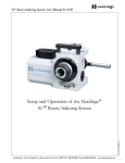
5. Insert the 3/16" drill bit into the through hole of the 3/16" SEAL-LOCK Jig. Set the Jig so that the
shoulder of the drill bit (not the point) and the fixed nib of the Jig are lined up. Set the drill bit
into the drill chuck so that the chuck rests on the top of the Jig and tighten. The depth of
succeeding holes is now set at 3/32".
http://ccvalves.com/seallock_manual.asp (4 of 13)28/07/2010 11:38:58 AM
Seal-Lock - Instruction Manual
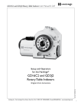
6. Insert the fixed nib of the Jig into the hole drilled in Step 3. The spring loaded nib will move up
into the body of the Jig. Place your 3/16" drill bit into the through hole in the Jig. Orient the Jig
so that the hole you are drilling is either above or below the crack and not lined up with the
crack. Drill hole. Follow this procedure with all holes drilled in Step 4.
7. Place the fixed nib of the Jig into the center holes drilled in Steps 3 and 4 and the spring loaded
nib in the holes just drilled in Step 6. Place your 3/16" drill bit in the through hole in the Jig and
drill a third hole. The 3/16" SEAL-LOCK patterns that you have just drilled consist of three
tangent holes, all drilled to a de0th of 3/32”, with the center hole located on the crack and the
other two holes on opposite sides of the crack. If all holes are not to an even depth, even them
out by eye. Remember - SEAL-LOCK pattern holes must never be drilled through the casting.
The SEAL-LOCKS must have a backing of cast iron to rest on. It any of the SEAL-LOCK
0atterr~ holes are accidentally drilled too deep and you should go through the casting, merely
tap the hole with 6 to 8 half turns of a #1 SEALACE High Speed Tap, insert a #1 SEALACE
Taper Plug, remove head and excess of the plug after the plug is snugged, grind the plug flush
with the casting and redrill the SEAL-LOCK hole over the plug.
http://ccvalves.com/seallock_manual.asp (5 of 13)28/07/2010 11:38:58 AM
Seal-Lock - Instruction Manual
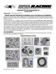
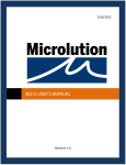
8. Place 3/16" (3 lobe) SEAL-LOCKS into the patterns that you have just drilled. Make sure that
the concave side of the SEAL-LOCKS are facing down. (See illustration)
Put a few drops of FLUID WELD into the pattern.
Using a hand held hammer, imbed SEAL-LOCKS in the patterns. This will flatten out the SEALLOCKS, setting them tightly in their patterns. (See illustration)
NOTE: Use 3/16" SEAL-LOCKS (5 lobe) if crack is gapped, or if more strength is desired in the
repair. Drill a 5 lobe pattern by drilling one additional hole above the crack and one additional
hole below the crack.
Peen the SEAL-LOCKS welt using an air hammer and a round end peening tip. Be careful not
to obscure the Center lobe of the SEAL-LOCKS where they meet the crack. This definition of
the center lobe must be maintained so that when drilling #I SEALACE holes, you are sure to
http://ccvalves.com/seallock_manual.asp (6 of 13)28/07/2010 11:38:58 AM
Seal-Lock - Instruction Manual
bite slightly into the center lobe of the SEAL-LOCKS.
9. Using a 3/16" drill bit, drill first #1 SEALACE holes on one side of the SEAL-LOCKS, through
the crack and into the water jacket (unless the casting is thicker than 1/2". In this event, only drill
to a depth of 1/2"). These holes must be drilled so that they bite slightly into the center lobe of
the SEAL-LOCKS.
10. Tap these holes with a #1 SEALACE High Speed Tap. SEALACE Taps are exceedingly sharp
and durable and cut very easily. Therefore take care not to tap too deep. Approximately 6 to 8
half turns of the tap will provide sufficient thread. Put a drop of FLUID WELD into the tapped
hole.
11. Insert #1 SEALACE Taper Plug into tapped holes and tighten plugs until heads and excess
above the surface of the casting torque off. This will occur when the SEALACE have tensioned
the SEA LOCKS to their maximum prestressing. Do not use other than SEALACE Tap Plugs or
this prestressing will not occur and the repair will not be snug enough. If the casting is thin the
SEALACE may not break off, but might continue to turn while being tightened. In this case,
snug up the SEALACE and remove the head and excess by scoring with a keyhole saw hack
saw blade and then twisting off the excess, or by culling with a bolt cutter, etc.
12. Drill second #1 SEALACE holes on opposite sides of SEAL-LOCKS Follow procedure as in
Steps 9, 10 and 11.
13. Notice that a space remains between the first and second SEALACE holes, just the proper size
for a third #1 SEALACE Taper Plug biting slightly into the first and second SEALACE. Drill a
hole for the third SEALACE in these spaces and follow the procedures in Steps 10 and 11. If
properly spaced - you now have a line along the crack consisting of a 3/16" SEAL-LOCI three
#1 SEALACE Taper Plugs, a 3/16” SEAL-LOCK, three #1 SEALACE Taper Plugs, etc. All
SEAL-LOCKS an SEALACE must bite into one another to make the repair leak-proof.
http://ccvalves.com/seallock_manual.asp (7 of 13)28/07/2010 11:38:58 AM
Seal-Lock - Instruction Manual
14. Using an Air Hammer and a round end peening tip, been the entire repair. First peen all of the
SEAL-LOCKS and then peen the SEALACE. Notice that the material used in the manufacture
of SEAL-LOCKS and SEALACE permits you to peen the repair together in one solid mass. This
peening also cold works (forges) the material to extremely high working Strengths, many times
Stronger than the cast iron being repaired.
15. Grind off all excess SEAL-LOCK and SEALACE material above the surface of the Casting. A
small die grinder and cut off wheel is recommended for best results, however grinding stones
ma also be used. Rotary files are not recommended since they do not leave a good
appearance. If the repair is on a machined or polished surface, take care in this finishing
process.
16. If the repair is on other than a machined or polished Surface, such as the side of a motor block,
fine peen the entire area using the SEAL-LOCK Air Hammer and a pointed fine peening tip.
Fine peening not only improves the cosmetics of the repair, but it also has a tendency to close
any areas of fine seepage.
If during a pressure test, the repair should leak it will be because:
a. The repair is not thoroughly peened.
b. #1 SEALACE adjacent to the center lobes of the SEAL-LOCK are not biting slightly into the center
lobe.
c. #1 SEALACE are not biting into each other.
THERE IS NO OTHER REASON WHY THE REPAIR CAN LEAK.
In any of these events - fine peen the area of seepage with the Air Hammer and a pointed fine peening
tip. If seepage continues - center punch the leaking spot, drill a hole through this spot with a 9/64" drill
bit. Tap the hole with a #4 SEALACE High Speed Tap, put a drop of FLUID WELD into the tapped
hole. Insert a #4 SEALACE Taper Plug, remove head and excess of the plug, peen with a round end
peening tip, 9rind off excess metal and fine been with a pointed fine peen log tip. Leaking will stop.
Larger SEAL-LOCKS and SEALACE Taper Plugs are available for repairing thicker Castings.
Repairing Blow-Out Holes
Repairing blow-out holes by patching, is merely a variation of the repair just discussed.
http://ccvalves.com/seallock_manual.asp (8 of 13)28/07/2010 11:38:58 AM
Seal-Lock - Instruction Manual
1. Grind hole or damaged area as uniform as possible.
2. Make patch to fit hole.
3. Secure patch in place with four (4) evenly spaced SEALACE Taper Plugs coated with FLUID
WELD.
4. Continue repair as if repairing 4 separate cracks.
Repairing Cracks Caused by Thermal Shock (Heating and Cooling)
These cracks are almost always found in the combustion chamber area of cylinder heads (valve-ports,
injector holes, etc.) or motor blocks (cylinders, etc.).
Since there is actually no continuous strain being placed on the crack, the repair is made (with some
few exceptions) entirely with SEALACE Taper Plugs.
SEALACE Taper Plugs will result in a stronger, more durable repair than a similar repair made with
cast iron plugs, for the following reasons:
1. The material from which SEALACE are manufactured is stronger, more corrosion resistant and
2.
3.
4.
5.
far more durable. Additionally, SEALACE cannot recrack as can cast iron plugs.
SEALACE Taper Plugs tighten and torque better, resulting in a tighter thread lit.
SEALACE Taper Plugs will never exhibit "thread burn".
The use of #1 SEALACE Taper Plugs almost exclusively in this type repair results in the
removal of a minimum amount of parent metal from the casting.
The expansion and contraction characteristics of SEALACE Taper Plugs under heating and
cooling in a combustion chamber is similar to the expansion and contraction of the cast iron
being repaired.
ONCE A CRACKED HEAD HAS BEEN PROPERLY REPAIRED WITH #1 SEALACE TAPER PLUGS,
IT SHOULD ACTUALLY PROVIDE BETTER SERVICE THAN A NEW HEAD - BECAUSE:
1. The cracked area has been Stress relieved.
2. The cracked cast iron has been replaced with a stronger, more durable material that can't
http://ccvalves.com/seallock_manual.asp (9 of 13)28/07/2010 11:38:58 AM
Seal-Lock - Instruction Manual
recrack.
Repairing Gasoline Heads (Cast Iron or Aluminum)
Cracks in overhead configured gasoline fueled heads, invariably occur from valve ports, or between
valve ports. The only consideration as to whether or not a repair can be made with SEALACE Taper
Plugs, is the accessibility of the crack. If the entire crack can be reached, it can be successfully
repaired.
If the crack occurs in a valve port, determine it seat is cast in or is an insert. It the seat is an insert.
REMOVE THE INSERT.
Starting slightly beyond one end of the crack, drill a hole with a 3/16" diameter drill bit, through the
crack and into the water jacket. Tap this hole with a # 1 SEALACE High Speed Tap. Put a drop of
FLUID WELD in the tapped hole.
Insert a #1 SEALACE Taper Plug in the tapped hole and snug up without breaking off the excess and
head of the plug.
Remove the head and excess of the plug by hack-sawing, knotching with a chisel, etc.
Drill the same size hole next to and slightly biting into the first SEALACE, directly through the crack.
Tap and insert SEALACE, then remove excess as above. Continue the same procedure along the
balance of the crack and right through seat area until you reach just slightly beyond the other end of
the crack.
When turning a corner or radius, angle drilled holes, so that the SEALACE Taper Plugs follow the
contour of the casting.
If insert had been removed prior to repair, replace with an oversize insert, if not, merely finish off seat
angle directly over SEALACE.
Peen the entire repair with the SEAL-LOCK Air Hammer and a round end peening tool. Take care in
peening machined and seated surfaces.
Grind off all excess repair material. Dress off repair. NOTE: If subsequent pressure test indicates any
areas of leakage, it is probably due to:
a. SEALACE not biting into each other.
b. Part of crack not repaired.
In this case, merely center punch the leaking #4 SEALACE area, drill a 9/64" diameter hole, insert a #4
SEALACE Taper Plug and dress off as before.
When Repairing Aluminum Heads
http://ccvalves.com/seallock_manual.asp (10 of 13)28/07/2010 11:38:58 AM
Seal-Lock - Instruction Manual
1. Do not tap as deep as you would in a cast iron head.
2. Always use a good quality tapping compound such as SEAL-LOCK TMT, to insure clean and
3.
4.
5.
6.
7.
uniform threads.
Use #4 SEALACE Taper Plugs to make the repair.
Never try to torque off the head of the plug.
Don't try to tighten the plug past its "snug point" as the plug might continue to tap the hole.
Remove the head of the plug by sawing or cutting with a cut off wheel. If you attempt to chisel
off the head of the plug, you just might pull it out from the threads.
Peen the repair very lightly. Cast aluminum is too soft to be peened as thoroughly as cast iron.
Repairing Diesel Heads
These repairs are essentially the same as the repair to gasoline heads.
However, since the cast iron in diesel heads is generally thicker than the cast iron in gasoline heads and since you do not want to drill SEALACE holes deeper than 1/2", you will sometimes be tapping
and inserting a SEALACE Taper Plug in a blind hole. To prevent against an air pocket, always insert
FLUID WELD in the tapped hole before inserting the SEALACE Taper Plug.
When repairing cracks from the injector holes of Detroit or Cummins Diesel Heads, angle the drilled
SEALACE hole AWAY from the injector tube.
When repairing cracks from the threaded injector hole of Caterpillar heads, start the first SEALACE
hole on the edge of the injector hole, just touching the first few threads Retap injector thread after
repair accomplished.
Thousands upon thousands of successful repairs have been made on these and other types of diesel
heads using only SEALACE Taper Plugs.
Remember to always pressure test the head to find any areas of unrepaired crack or to detect areas
where SEALACE Taper Plugs might not be biting into each other.
ALWAYS TAKE CARE IN HANDLING AND FINISHING OFF MACHINED HEAD SURFACES.
When installing valve seat inserts, always put a bead of FLUID WELD in the undercut before installing
the insert.
With the exception of some cylinder heads in excess of an 8" bore, NEVER USE SEAL-LOCKS in the
repair. If you are ever confronted with a head of this size, call the main office of SEAL-LOCK
INTERNATIONAL, your SEAL-LOCK Representative, for repair instructions.
SEAL-LOCK Guide
http://ccvalves.com/seallock_manual.asp (11 of 13)28/07/2010 11:38:58 AM
Seal-Lock - Instruction Manual
Size of
SEALLOCK
Use on
Casting
thicknesses
Drill
Size
Distance
Between
Patterns
Optimum
Depth of
Pattern
3/16" 3
Lobe
5/32"- 114"
Thick *
3/16" *
3/4" Centers
3/32"- 118"
3/16" 5
Lobe
5/32"- 114"
Thick *
3/16" *
3/4" Centers
3/32"-118"
1/4" Thin
3/16" - 1/4" Thick 17/64" *
718" Centers 3/32" - 118"
1/4" Thick 1/4" - 3/8" Thick
17/64" *
718" Centers
3/16" - 7132
*
3/8" Thin
Use to Laminate
in Castings
More Than 3/4"
Thick
13/32" *
As Required
Laminate
any Depth
3/8" Thick
More Than 3/8"
Thick
13/32" *
As Required
3/16" - 7~32
*
SEALACE Guide
Size of SEALACE
Use on Casting Thicknesses
Drill Size
#1 SEALACE
5/32" - 1/2" Thick
3/16"
#3 SEALACE
1/2" Thick and Up General Repairs
17/64"
#4 SEALACE
1/16" - 1/2" Thick
9/64"
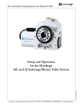
* The bottoms of SEAL-LOCK patterns should be drilled as flat as
possible. We recommend the use of jobber length, high speed drill bits,
ground to a 135° angle.
Bottom of pattern drilled with regularly sharpened drill
bit.
Bottom of pattern drilled with drill bit ground to a 135°
angle.
When using 1/4" Thin SEAL-LOCKS use 17/64" drill, drill five lobe
pattern to a depth of 3/32" and space patterns on 7/8" center. This
permits four #1 SEALACE Taper Plugs between SEAL-LOCK patterns.
Special instruction is required on the use of 1/4" Thick SEAL-LOCKS
http://ccvalves.com/seallock_manual.asp (12 of 13)28/07/2010 11:38:58 AM
Seal-Lock - Instruction Manual
and 3/8" SEAL-LOCKS, Thin and Thick.
The SEAL-LOCK Process is covered by U.S. and Canadian patents and/or patents pending. World rights reserved.
SEAL-LOCK, SEALACE and FLUID WELD are registered trademarks of SEAL-LOC INTERNATIONAL.
http://ccvalves.com/seallock_manual.asp (13 of 13)28/07/2010 11:38:58 AM