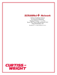
1
PG&E SCADA Communication Option For Use With the S&C IntelliCAP PLUS® Automatic Capacitor Control S&C Electric Company 1135 Atlantic Avenue Alameda, California USA 1023-562 / 2-20-06 PG&E SCADA Communication Option for the IntelliCAP PLUS Capacitor Control S&C Electric Company Proprietary Information Proprietary Notice This document contains information which is proprietary to S&C Electric Company and is provided under the terms and conditions of a Purchase Order Terms and Conditions Agreement between S&C Electric Company and each of its customers. Disclosure of information contained in this document to third parties without prior written permission from S&C Electric Company is strictly forbidden. Information in this manual is subject to change without notice and does not represent a commitment on the part of the vendor. Copyright © 2006 S&C Electric Company All Rights Reserved. Printed in the USA. IntelliCAP PLUS, and WinMon are registered trademarks of S&C Electric Company Cellnet is a registered trademark of Cellnet Hayes is a trademark of Hayes Microcomputer Products, Inc. IBM is a registered trademark of International Business Machines Corporation. UtiliNet is a registered trademark of Cellnet Motorola is a registered trademark of Motorola, Inc. MS-DOS and Windows are registered trademarks of Microsoft Corporation. All other trademarks are the property of their respective holders. S&C Electric Company, 1135 Atlantic Avenue, Alameda, CA 94501, USA Tel (510) 864-6850/ FAX (510) 864-6860 2 PG&E SCADA Supplement 1023-562 / 2-20-06 S&C Electric Company Proprietary Information PG&E SCADA Communication Option for the IntelliCAP PLUS Capacitor Control Contents Introduction_____________________________________________________________5 Applicable Software ____________________________________________________5 Document Conventions __________________________________________________5 Cautions______________________________________________________________5 Communications Hardware ________________________________________________6 Communications Setup and Installation _______________________________________7 PG&E SCADA Software Implementation ____________________________________14 Status Points _________________________________________________________14 Analog Input Points____________________________________________________15 Control Points ________________________________________________________19 PG&E Protocol Functions Implemented _____________________________________24 Access to Setpoints and Data Logging Results Via PG&E Protocol ________________24 Extended Error Code File Definitions _______________________________________25 1023-562 / 2-20-06 PG&E SCADA Supplement 3 PG&E SCADA Communication Option for the IntelliCAP PLUS Capacitor Control S&C Electric Company Proprietary Information Notes: 4 PG&E SCADA Supplement 1023-562 / 2-20-06 S&C Electric Company Proprietary Information PG&E SCADA Communication Option for the IntelliCAP PLUS Capacitor Control Introduction This supplement describes the hardware and software support for the PG&E SCADA communications protocol in the S&C IntelliCAP PLUS Single-Phase Programmable Capacitor Control. Applicable Software This document was prepared for use with software PCSP118S and PCVP118S. You can find the release date on the Setup disk’s label and on the PRODUCT INFORMATION screen. For questions regarding the applicability of the information in this document to future software releases, please contact S&C Electric Company. Document Conventions The following conventions are used in this document: BOLD UPPER CASE Labels on faceplates and assemblies; switch positions. Italic Names of manuals, manual sections, and software screens. “Quotes” Names of fields on software screens. <Brackets> Names of computer keyboard keys. Courier Characters to be typed at the DOS prompt and commands issued by the SCADA master station. Cautions All Cautions are clearly marked with the notation ! CAUTION !. Please read all cautions carefully before attempting to install or operate this equipment. ! CAUTION ! The information in this document is meant only for qualified people who are properly trained for work with this type of equipment, and who understand the hazards that may be involved. The information in this document is not meant to be a substitute for training and experience in the safety procedures that are required for this type of equipment. 1023-562 / 2-20-06 PG&E SCADA Supplement 5 PG&E SCADA Communication Option for the IntelliCAP PLUS Capacitor Control S&C Electric Company Proprietary Information Communications Hardware The IntelliCAP PLUS Capacitor Control is compatible with several communications hardware systems, including: • UtiliNet® • MDS • CellNet® • Cellular Telephones • Fiber Optics • Hayes™-compatible modems • Phone Lines Each communications hardware option can be factory- or field-installed. If the factory installs the communications hardware, the cables are connected before the Capacitor Control is shipped. For field installation, an installation guide comes with the manual or retrofit kit. 6 PG&E SCADA Supplement 1023-562 / 2-20-06 S&C Electric Company Proprietary Information PG&E SCADA Communication Option for the IntelliCAP PLUS Capacitor Control Communications Setup and Installation Typically, S&C Electric Company provides Controls with the requested communications options already installed in the enclosure. You may be able to skip some of the following steps. ! CAUTION ! Do not enable communications by connecting dedicated phone lines, antennas, or fiber optic cables until this is called out in the instructions. If the device address is incorrect when communication is enabled, the Control could respond to master station communications intended for a different device. This could interfere with normal system operation. Before attempting to access an existing installation, check carefully for visible or audible signs of electrical or physical malfunction (do this before touching or operating the Control or any other part of the installation). These warning signs include such things as smoke, fire, open fuses, crackling noises, loud buzzing, etc. If a malfunction is suspected, treat all components of the installation, including the Control and associated mounting hardware, as if they were elevated to primary (high) voltage. A. Installing the Hardware 1. Plug the control into the meter base socket, if required. When the control is plugged into an energized meter base, all faceplate LEDs light momentarily. The LCD starts to scroll after a few seconds. 2. Remove the fuse on the faceplate. 3. Make sure that the OPERATION MODE MANUAL and SCADA CONTROL LOCAL LEDs are lit. If not, press the applicable CHANGE button. Figure 1 Faceplate SCADA PORT 1023-562 / 2-20-06 PG&E SCADA Supplement 7 PG&E SCADA Communication Option for the IntelliCAP PLUS Capacitor Control S&C Electric Company Proprietary Information Check to make sure no communications equipment is able to receive or transmit signals. If communications equipment is already installed, disconnect the power and communications SCADA PORT connector. • For an external radio, disconnect the communications cable from the box receptacle on the bottom of the Capacitor Control. • For all other communications options, disconnect the SCADA PORT connector on the faceplate (see Figure 1). 5. If you need to install the communications equipment in the enclosure, disconnect any current and/or neutral sensors and pull the Capacitor Control off the pole (See Figure 2). Install the radio or other device, following the installation guide. Replace the Capacitor Control on the pole and reconnect the current sensors. NOTE: Do not connect the phone line, antenna, or fiber optic cable at this time. 6. When you are finished installing the communications hardware, replace the fuse. Figure 2 Ground Lug, Sensor Input Connectors and optional LED Neutral Current / Voltage Lockout Indicator B. Setting the Correct Communications Address 1. Connect the Capacitor Control to an IBM®/PC-compatible computer, using the optical port on the side of the enclosure or to the DB9 connector on the front of the faceplate, labeled LOCAL COMM. PORT (See Figure 1). 2. Double-click the IntelliLINK icon Windows desktop. in the open EnergyLine folder on the If the EnergyLine folder is not open, open the Windows Start menu, then click Start > Programs > EnergyLine > IntelliLINK to start the software. 3. Wait while the IntelliLINK window appears and the IntelliLINK software attempts to open communications with the capacitor control. 8 PG&E SCADA Supplement 1023-562 / 2-20-06 S&C Electric Company Proprietary Information PG&E SCADA Communication Option for the IntelliCAP PLUS Capacitor Control When the IntelliLINK software establishes communications with the capacitor control, the Operation screen (Figure 3) opens. Figure 3 Operation Screen for the IntelliCAP PLUS IntelliLINK Software (VAR with Neutral Current Version) NOTE: If the IntelliLINK software does NOT establish communications with a functioning capacitor control, it displays the following dialog box. If this dialog box appears, or if the Operation screen opens but the software does not operate properly, see Software Troubleshooting and Error Messages in the Troubleshooting chapter. 1023-562 / 2-20-06 PG&E SCADA Supplement 9 PG&E SCADA Communication Option for the IntelliCAP PLUS Capacitor Control S&C Electric Company Proprietary Information 4. On the Operations screen, select the Comm button to display Page 1 of the Communications Setup screen (see Figure 4). 5. Set the communications setpoints to the proper values. Figure 4 Page 1 of the Communications Setup Screen 6. This screen contains the following fields: Communications RTU Address (if applicable). Depending on the SCADA communications option installed in the control, this parameter sets the appropriate communications address. NOTE: Be sure to set this address properly before physically connecting communications to ensure that the control does not respond to requests intended for another device. SCADA Communication Baud Rate 10 PG&E SCADA Supplement 1023-562 / 2-20-06 S&C Electric Company Proprietary Information PG&E SCADA Communication Option for the IntelliCAP PLUS Capacitor Control This setpoint provides user selection of baud rate for the SCADA port. A number of baud rates from 300 to 9600 may be selected. Please make sure the selected baud rate matches the baud rate of the connected SCADA equipment (modem, radio, etc.). If configured improperly, SCADA communications will be inoperable. Transmitter Keying Delay Time (ms) This value specifies the amount of time that must elapse from the moment the transmitter is turned on until the data transmission begins. Transmitter Turn-Off Delay Time (ms) This value specifies the amount of time the transmitter should remain on after the second to last character transmission has begun. Allow RTU Memory Write Operations For security reasons, SCADA ordinal writes (Function 20h, Commands 30h and 31h) are by default disabled in the capacitor control. If you enable this feature to access some specific memory locations, you should also disable it when you are done. This prevents inadvertent changes to capacitor control parameters. Allow Duplicate Operate Commands Enabling this setpoint will allow the capacitor control to accept a duplicate Operate command for any given Select-Before-Operate sequence. While this is not covered by the PG&E SCADA protocol, this may be useful if your communications system is unreliable, and also is able to retry failed requests. For example, if a response to an Operate command failed to return to the master station, and a retry of the Operate was generated, if the duplicate Operate was received within the original Select timeout period, the capacitor control would respond as if the Operate had just occurred rather than with an error. 7. At page 1 of the Communications Setup screen, click the Pg Dn button to display Page 2 of the Communications Setup screen (Figure 5). This TROUBLESHOOTING: Communications screen shows a chronological listing of communications problems related to the PG&E protocol on port A. The log can hold 10 entries. Once the log is full, each new event over-writes the oldest event in the log. To find the most recent event, look for the message with a timestamp that is older than the time for the message above it. 1023-562 / 2-20-06 PG&E SCADA Supplement 11 PG&E SCADA Communication Option for the IntelliCAP PLUS Capacitor Control S&C Electric Company Proprietary Information Figure 5 Page 2 of the Communications Setup Screen Detailed parameter descriptions for this screen are: Date/Time This is the date and time when the event occurred. Reason for Communications Failure This is the reason that communications failed. If a message fails at the data link layer of PG&E SCADA, one of the following messages appears: “Packet CRC Error” “Internal: Bad UART interrupt” “Packet size inconsistent with command” “Packet size illegal” “Packet size too small for this command” “Packet contains bad characters/framing” If a message fails at the application layer of PG&E SCADA, one of the following messages appears: “Invalid function code or command received” 12 PG&E SCADA Supplement 1023-562 / 2-20-06 S&C Electric Company Proprietary Information PG&E SCADA Communication Option for the IntelliCAP PLUS Capacitor Control “Control requested on invalid channel” “Channel not selected before operate” “Control selection timed out” “Control selection followed by non-operate” “Control requested while in LOCAL mode” Fnc This is the PG&E SCADA function code for this communications failure. It can provide additional information about the packet received. (For more details, see PG&E SCADA protocol documentation.) Cmd This is the PG&E SCADA command code for this communications failure. It can provide additional information about the packet received. (For more details, see PG&E SCADA protocol documentation.) 8. Connect the SCADA PORT connector on the faceplate. For an external radio, connect the communications cable. 9. Replace the fuse. 10. For Automatic operation, (make sure Scada Control is in the local mode) hit the change button under Operation Mode to switch to Auto Mode For remote operation, hit the change button under Scada Control to switch to REMOTE when leaving the site. ! CAUTION ! When the Operation Mode is set to AUTO, automatic operation of the Capacitor Control resumes. Be aware that the Control can carry out commands from the automatic control logic. In addition, if Scada Control is in REMOTE, the Control can carry out commands from the SCADA master station. 1023-562 / 2-20-06 PG&E SCADA Supplement 13 PG&E SCADA Communication Option for the IntelliCAP PLUS Capacitor Control S&C Electric Company Proprietary Information PG&E SCADA Software Implementation For accessing the IntelliCAP PLUS Capacitor Control, the master station should define the Control with the following I/O: Status Points 15 Analog Input Points 28 Control Points 5 The points are defined in the tables below. Note that you can access all digital input points as either single-bit status or two-bit status values. Status Points Status Point # 14 Definition 1 Capacitor bank Close state. This bit is set if the capacitor bank is switched in. 2 Capacitor bank Open state. This bit is set if the capacitor bank is switched out. 3 AUTO/MANUAL operation mode. This bit is set when the control is in the AUTO position. 4 REMOTE/LOCAL SCADA control mode. This bit is set when the control is in the REMOTE position. When in the LOCAL mode, operation of the bank from the SCADA master station is blocked. 5 Voltage override alarm status. This bit is set when an over/under voltage condition is present. 6 Timeclock/temperature control mode. This bit is set if the Capacitor Control is operating in “Timeclock” control mode. NOTE: This point is not generally useful since there are several control strategies from which to choose. 7 Not Used. 8 Automatic control state. This bit is set if the bank is requested to be in circuit by the presently active control strategy. Unless the control logic has been overridden by a hardware manual override or by a voltage alarm condition, this corresponds to the present state of the bank, i.e. the bit is set if the bank is in circuit (closed). PG&E SCADA Supplement 1023-562 / 2-20-06 S&C Electric Company Proprietary Information Status Point # 9 PG&E SCADA Communication Option for the IntelliCAP PLUS Capacitor Control Definition VAR VAR with Neutral Sensor Reverse current. This bit is set if the Control has detected that the direction of current flow is reversed from the normal direction. This should only occur during emergency switching operations. Standard; Neutral N.A. Sensor 10 Maintenance required. This bit is set when the Capacitor Control reaches the “Maximum Automatic Control Cycles Per Day”; when the Control detects a temperature sensor, voltage sensor, “Load Fuse Blown” error; or when there is a voltage bandwidth error. See the Troubleshooting chapter of the User’s Manual for details. 11 Neutral Sensor VAR with Neutral Sensor Neutral sensor lockout. This bit is set when the neutral current or voltage remains above the “Neutral Alarm Level” for a period of time specified by the “Current or Voltage Change Time Threshold.” The Control performs corrective action, if enabled, and locks out if the condition has not been cleared. The alarm stays on unless manually reset. To reset, issue a “Reset NS Lockout” command. If neutral current or voltage flow still exists, the alarm will be reinitiated. 12 Neutral Sensor VAR with Neutral Sensor Continuous neutral sensor alarm. This bit is set when the neutral current or voltage remains above the “Neutral Sensor Alarm Level” for a period of time specified by the “Neutral Current or Voltage Change Time Threshold.” It is reset if the neutral value falls below the “Neutral Current or Voltage Alarm Level.” If the neutral retry feature is enabled, this bit remains set prior to the retry. If the retry is unsuccessful, the neutral alarm bit remains set. 13 SCADA Override enabled. This bit is set when the SCADA Override feature is enabled in the setup software. This override strategy may or may not be controlling the bank state when enabled, depending on the state of other overrides and SCADA commands that have been issued. 14 Neutral Sensor Alarming. This bit is zero when Neutral Sensor Alarming 1023-562 / 2-20-06 PG&E SCADA Supplement 15 PG&E SCADA Communication Option for the IntelliCAP PLUS Capacitor Control S&C Electric Company Proprietary Information is based on fundamental RMS measurements, using only the 60 Hz component of the neutral voltage or neutral current. This bit is set when the total RMS measurement is the basis for this alarm. 15 Neutral Sensor Data Logging. This bit is zero when Neutral Sensor Data Logging is based on fundamental RMS measurements, using only the 60 Hz component of the neutral voltage or neutral current. This bit is set when the total RMS measurement is the value logged. Analog Input Points Analog Input Point # Definition 1 90% voltage reference standard. This is provided for the benefit of the protocol implementation to conform to the RTU standard. It is loaded as a constant. 2 0% voltage reference standard. This is provided for the benefit of the protocol implementation to conform to the RTU standard. It is loaded as a constant with the value zero. 3 The most recent temperature reading. This value is in units of °F or °C as selected in the IntelliLINK Setup Software. 4 Most recent voltage measurement. Each count equals 0.1 Vac RMS. 5 VAR VAR with Neutral Sensor Phase angle. Each count equals one eighth of a degree, with an offset of 90°. Standard; Neutral Returns a zero. Sensor 6 VAR VAR with Neutral Sensor Three-phase kVARs. KVARs (Volt-amperes reactive) are calculated from the measured single phase voltage, current and phase angle times three. Each count equals 4 kVARs. A value of zero corresponds to 8188 kVARs leading. Standard; Neutral Returns –8188. Sensor 7 16 VAR VAR with Neutral Single-phase line current. Each count equals 1 ampere. PG&E SCADA Supplement 1023-562 / 2-20-06 S&C Electric Company Proprietary Information PG&E SCADA Communication Option for the IntelliCAP PLUS Capacitor Control Sensor Standard; Neutral Sensor 8 Three-phase kVA. The single-phase kVA is multiplied by three. Each count is 4 kVAs. NOTE: This analog does not apply to non-VAR versions. Standard; Neutral Sensor 9 10 Returns a zero. Returns a zero. Three-phase kW. The single-phase kW is multiplied by three. Each count is 4 kWs. NOTE: This analog does not apply to non-VAR versions. Standard; Neutral Sensor Returns a Zero. Neutral Sensor VAR with Neutral Sensor The most recent neutral current or voltage reading. Each count equals 1 ampere or volt. Standard; VAR Returns a zero. 11 Voltage, % total harmonic distortion (THD). 12 Voltage, % third harmonic distortion. 13 Voltage, % fifth harmonic distortion. 14 Voltage, % seventh harmonic distortion. 15 Current, % total harmonic distortion (THD). Non-VAR units return zero. 16 Current, % third harmonic distortion. Non-VAR units return zero. 1023-562 / 2-20-06 PG&E SCADA Supplement 17 PG&E SCADA Communication Option for the IntelliCAP PLUS Capacitor Control 17 S&C Electric Company Proprietary Information Current, % fifth harmonic distortion. Non-VAR units return zero. 18 Current, % seventh harmonic distortion. Non-VAR units return zero. 19 Neutral, % total harmonic distortion (THD). Non-Neutral units return zero. 20 Neutral, % third harmonic distortion. Non-Neutral units return zero. 21 Neutral, % fifth harmonic distortion. Non-Neutral units return zero. 22 Neutral, % seventh harmonic distortion. Non-Neutral units return zero. 23 18 The time remaining in SCADA Override mode. If in timed mode, displays minutes remaining, if in latched mode, returns 4095. PG&E SCADA Supplement 1023-562 / 2-20-06 S&C Electric Company Proprietary Information 24 PG&E SCADA Communication Option for the IntelliCAP PLUS Capacitor Control Control Strategy. This is the presently configured control strategy in use. The possible values are: 0 1 2 3 4 5 6 7 8 9 10 11 12 13 14 Temperature Timeclock Voltage Only Time-Biased Voltage Time-Biased Temperature Auto Off-Line Mode Auto On-Line Mode Current VAR Reverse Current Voltage Only Temperature Sensor Error, Voltage Only SCADA Override Timeclock with Temperature Override Current with Temperature Override VAR with Temperature Override NOTE: Values 7, 8, 9, 13, and 14 do not apply to non-VAR versions. 25 The last switch in or out voltage delta. Each count is 0.1 Volt. This will be a signed value if the switch after voltage is less than the before switching voltage. 26 Neutral current or Neutral voltage, the data reported is the total harmonic RMS value. Each count equals 1 ampere for a control with neutral current sensing installed, or each count equals 1 Volt for a control with neutral voltage sensing installed. NOTE: Versions without the Neutral option will return a 0 value. 27 Primary Line Voltage. Each count equals 10 Vac RMS. 28 Power Factor. The data reported is the cosine of the phase angle. Leading power factors are represented by negative numbers. Each count equals 0.001 with a 1000 offset (0 = -1.0, 1000 = 0.0, 2000 = 1.0). 1023-562 / 2-20-06 PG&E SCADA Supplement 19 PG&E SCADA Communication Option for the IntelliCAP PLUS Capacitor Control S&C Electric Company Proprietary Information Control Points You can use the control points listed below to override the automatic operation of the capacitor bank. Control Point # Definition 1 Issue the Close/Open command to the switch. A Control-Select-Close command to this point switches the bank into the circuit. A ControlSelect-Open command switches the bank out of the circuit. The command returns an error if the faceplate REMOTE/LOCAL switch is not in the REMOTE position. 2 Not Used. 3 Enable or disable “Automatic” operation. A Control-Select-Close command enables Automatic operation. A Control-Select-Open command disables Automatic operation (Manual Operation is enabled). 4 Enable or disable “SCADA Override” mode. A Control-Select-Close command enables SCADA Override. A Control-Select-Open command disables SCADA Override. 5 Reset NS Lockout. A Control-Select-Close command resets a Neutral Sensor Lockout condition. The next several pages show sample scheduler (Figure 1), dbase (Figure 2), and display (Figure 3) files for PG&E’s FVISION PC SCADA software. These files and all others necessary to run the program are provided on the Setup disk. 20 PG&E SCADA Supplement 1023-562 / 2-20-06 S&C Electric Company Proprietary Information PG&E SCADA Communication Option for the IntelliCAP PLUS Capacitor Control SCHEDULE.FOV – S&C IntelliCAP PLUS Automatic Capacitor Control - Basic Version Prty Offst COM M# R# CType FCode Cmmd SSI SSCt 2BSI 2BSCt ANAI ANACt ANPI ANPCt PAII PAICt CtrlI SNum P1 P2 Descrip 1 0 1 0 00000 1 $00 $11 1 13 0 00 1 23 0 0 0 0 0 0 0 0 Digital/Analog Inputs 1 0 1 0 00000 2 $10 $11 0 0 0 00 0 0 0 0 0 0 1 0 0 0 Close Switch 1 0 1 0 00000 4 $10 $20 0 0 0 00 0 0 0 0 0 0 1 0 0 0 Bank in Circuit 1 0 1 0 00000 2 $10 $10 0 0 0 00 0 0 0 0 0 0 2 0 0 0 Open Switch 1 0 1 0 00000 4 $10 $20 0 0 0 00 0 0 0 0 0 0 2 0 0 0 Bank Out of Ckt. 1 0 1 0 00000 2 $10 $11 0 0 0 00 0 0 0 0 0 0 3 2 0 0 Enable Auto. Control 1 0 1 0 00000 4 $10 $20 0 0 0 00 0 0 0 0 0 0 3 0 0 0 Auto. Control Enabled 1 0 1 0 00000 2 $10 $10 0 0 0 00 0 0 0 0 0 0 4 2 0 0 Enable Manual Control 1 0 1 0 00000 4 $10 $20 0 0 0 00 0 0 0 0 0 0 4 0 0 0 Manual Control Enabled 1 0 1 0 00000 2 $10 $11 0 0 0 00 0 0 0 0 0 0 5 3 0 0 Enable Scada Override 1 0 1 0 00000 4 $10 $20 0 0 0 00 0 0 0 0 0 0 5 0 0 0 Scada Override Enabled 1 0 1 0 00000 2 $10 $10 0 0 0 00 0 0 0 0 0 0 6 3 0 0 Disable Scada Override 1 0 1 0 00000 4 $10 $20 0 0 0 00 0 0 0 0 0 0 6 0 0 0 Scada Override Disabled 1 0 1 0 00000 2 $10 $11 0 0 0 00 0 0 0 0 0 0 7 4 0 0 Reset Neutral Lockout Request 1 0 1 0 00000 4 $10 $20 0 0 0 00 0 0 0 0 0 0 7 0 0 0 Lockout Reset Figure 1 File SCHEDULE.FOV for S&C IntelliCAP PLUS Automatic Capacitor Control (VAR with Neutral Current) 1023-562 / 2-20-06 PG&E SCADA Supplement 21 PG&E SCADA Communication Option for the IntelliCAP PLUS Capacitor Control S&C Electric Company Proprietary Information ;DBASE.FOV – S&C IntelliCAP PLUS Automatic Capacitor Control - Neutral Current with VAR Option ;TYPE INDEX TAG PREC ROUTINE P1 P2 P3 P4 P5 P6 P7-P10 A 3 TEMP 72 S 0 4045 0 0 A 4 VOLTAGE 81 r 0 0 0 0 .1 A 5 PHASE 83 r 0 0 0 0 .125 A 6 KVARS 60 S -8188 8192 0 0 A 7 CURRENT 40 S 0 4095 0 0 A 9 KW 80 r 0 0 0 0 4 A 8 KVA 80 r 0 0 0 0 4 A 10 NEUTSENS 60 r 0 0 0 0 1 DESCRIPTION ; Temperature Sensor ; Voltage Sensor ; Corrected Phase Angle ; Calculated kVARs ; Phase Current ; Active Power ; Apparent power ; Neutral sensor Volts or Current A A A A A A A A A A A A A D D D D D D D D D D D D C C C C ; Cap. Bank Close Relay ; Cap. Bank Close Relay ; Cap. Bank Close Relay ; Cap. Bank Close Relay ; Cap. Bank Close Relay ; Cap. Bank Close Relay ; Cap. Bank Close Relay ; Cap. Bank Close Relay ; Cap. Bank Close Relay ; Cap. Bank Close Relay ; Cap. Bank Close Relay ; Cap. Bank Close Relay ; Cap. Bank Close Relay ; Cap. Bank Close Relay ; Cap. Bank Open Relay ; Auto/Manual Switch ; Remote/Local Oper. Mode ; Voltage Override ; Time/Temperature Control ; Softw. manual ctl. ; Time/temp ctl state. ; Reverse Current ; Maintenance Conditions ; Neutral Current Alarm ; Cont. Neutral Current Alarm ; Manual Caps In Ckt. ; Manual Caps Out of Ckt. ; Automatic Cap. Bank Control ; Manual Cap. Bank Control 11 12 13 14 15 16 17 18 19 20 21 22 23 1 2 3 4 5 6 7 8 9 10 11 12 1 2 3 4 VOLTTHD CAPSIN CAPSIN CAPSIN CAPSIN CAPSIN CAPSIN CAPSIN CAPSIN CAPSIN CAPSIN CAPSIN CAPSIN CAPSIN CAPSOUT AUTO REMOTE V.OVER. MODE H.OVER AUTOMDE REVCRNT MAINT. NCALARM CNCALR CLOSE OPEN AUTO MANUAL 81 xx xx xx xx xx xx xx xx xx xx xx xx xx xx xx xx xx xx xx xx xx xx xx xx xx xx xx xx D D D D D D D D D D D D D D D D D D D D D D D D D C C C C Open Closed 0 Open Closed 0 Open Closed 0 Open Closed 0 Open Closed 0 Open Closed 0 Open Closed 0 Open Closed 0 Open Closed 0 Open Closed 0 Open Closed 0 Open Closed 0 Open Closed 0 Open Closed 0 Open Closed 0 Manual Auto 0 Local Remote 0 Normal Override 0 Temp. Time 0 Manual Auto 0 Open Close 0 Normal Reverse 0 O.K. Bad 0 OFF ON 0 OFF ON 0 CIN 0 0 COUT 0 0 AUTO 0 0 MANUAL 0 0 0 0 0 0 0 0 0 0 0 0 0 0 0 0 0 0 0 0 0 0 0 0 0 0 0 0 0 0 0 3 3 3 3 3 3 3 3 3 3 3 3 3 3 3 4 4 3 3 3 3 3 3 3 3 4 4 4 4 4 4 4 4 4 4 4 4 4 4 4 3 3 4 3 4 3 3 3 4 4 Figure 2 File DBASE.FOV for S&C IntelliCAP PLUS Automatic Capacitor Control (VAR with Neutral Current) 22 PG&E SCADA Supplement 1023-562 / 2-20-06 S&C Electric Company Proprietary Information PG&E SCADA Communication Option for the IntelliCAP PLUS Capacitor Control ;S&C IntelliCAP PLUS Automatic Capacitor Control - Neutral Current Sensing with VAR Option ;DISPLAY 1 DATA FILE ;TYPE INDEX ROW COL PREC/SYM COMMENT A 4 16 30 51 ; Voltage A 3 17 30 50 ; Temperature A 8 18 30 50 ; Neutral Current A 6 16 61 80 ; KVARs A 7 17 61 80 ; Current A 5 18 61 83 ; Power Angle D 1 8 66 84 ; Close Relay Contact D D D D D D D D D D D 2 3 4 5 6 7 8 9 10 11 12 9 5 6 12 13 10 14 20 21 20 21 66 66 66 66 66 66 66 66 66 36 36 84 84 84 84 84 84 84 84 84 84 84 ; Open Relay Contact ; Hardware Manual Override ; Remote SCADA enable Switch ; Voltage Override active ; Time/Temp. control type ; Software Manual Enable ; Timeclock state ; Reverse current ; Maintenance Conditions ; Neutral Current Alarm ; Continuous Neutral Current Alarm Figure 3 File DISPLAY1.FOV for S&C IntelliCAP PLUS Automatic Capacitor Control (VAR with Neutral Current) 1023-562 / 2-20-06 PG&E SCADA Supplement 23 PG&E SCADA Communication Option for the IntelliCAP PLUS Capacitor Control S&C Electric Company Proprietary Information PG&E Protocol Functions Implemented The following PG&E SCADA communications protocol functions and commands have been implemented: 1. Basic Scan, Function Code $00, for all data types supported in the Capacitor Control. The “packed analog” form of encoding analog data is not supported. 2. Scan Inclusive, Function Code $01. As with the Basic Scan function, packed analog encoding is not supported. 3. Scan-By-Table, Function Code $0A. As with the Basic Scan function, packed analog encoding is not supported. 4. Supervisory Control, Function Code $10. The commands Direct Digital Control, Direct Open, Direct Close, and High Resolution Proportional Control are not supported. 5. The following Internal Control Function (Function Code $20) commands are implemented: • Initialize RTU Configuration (Standard Mode), Command Code $00. • Accumulator Freeze, Command Code $10. • Accumulator Reset, Command Code $11. • Initialize Specified Status Counter, Command Code $20. • Initialize All Status Counters, Command Code $21. • Write to RTU Memory, Command Code $30. (See section below for details.) • Execute Write Memory, Command Code $31. (See section below for details.) Access to Setpoints and Data Logging Results Via PG&E Protocol The implementation of PG&E SCADA also supports memory-mapped access to the entire collection of setup, real-time, and long term statistical and operating data. The complete memory map for the Capacitor Control is available from S&C. The memory access feature of the protocol is used to transfer the data to the master station. The memory is accessed as ordinal number 5 (RTU RAM memory). Function 28, Command 30 (Return RTU Configuration) is used to read data from the 24 PG&E SCADA Supplement 1023-562 / 2-20-06 S&C Electric Company Proprietary Information PG&E SCADA Communication Option for the IntelliCAP PLUS Capacitor Control Control. Function 20, Commands 30 and 31 (Write RTU Memory and Execute Write Memory) are used to write to the setpoints. To prevent incorrect or inadvertent writing to the Capacitor Control, a memory interlock has been implemented. Before memory write commands will be executed, you must make an initial write of the value integer 1 to location $04ED. When all writing operations are complete, set $04ED back to zero. For further information on this form of memory access, contact S&C. Extended Error Code File Definitions The codes assigned for inclusion in the “Error Code File” have been extended in this protocol implementation to provide additional detail on communications failures. The definitions of the additional codes are as follows: Code (HEX) Interpretation F0 CRC error on incoming packet – Suspect bad reception if intermittent, otherwise check master station software. F1 Bad interrupt (internal software error) – Notify S&C. F2 Packet timeout during receipt – Intercharacter delay greater than 40 milliseconds – Suspect bad reception if intermittent, otherwise master station has excessive intercharacter delay. F3 REMOTE/LOCAL switch in LOCAL position on Capacitor Control faceplate. F4 Length of incoming packet inconsistent with packet type – Suspect bad reception if intermittent, otherwise check master station software. F5 Illegal incoming packet length – Check master station software. F6 Control operating mode inconsistent with command – Not in software manual mode when software manual operation requested – Use “manual” command, then retry request. F7 Incoming packet does not have enough data in data field – Suspect bad reception if intermittent, otherwise check master station software. F8 Ordinal read/write not supported. F9 Memory pointer bad, no data to transfer – Check master station software. FA Character received with bad framing, parity, break rcvd, etc. – Probable bad reception or modem failure. 1023-562 / 2-20-06 PG&E SCADA Supplement 25