1
User Manual UM 1187
Group: Controls
PN: 300040523
Date: September 2000
MicroTech® Monitor 2.01
For Windows 95/98™
User Manual
© 2013 Daikin Applied
Daikin
Page ii
CONTENTS
INTRODUCTION ...........................................................................V
What You Need to Run The Monitor Program...................................................... vi
Hardware ................................................................................................................. vi
Software .................................................................................................................. vi
About The Monitor Documentation ....................................................................... vii
Components............................................................................................................ vii
PART 1 .......................................................... GETTING STARTED 1
Chapter 1 - Preparing Your Computer System....................................................... 2
Setting Up Hardware ................................................................................................ 2
Making Backup Copies ............................................................................................ 2
Installing Software ................................................................................................... 3
Chapter 2 - Learning the Basics................................................................................ 7
Starting Monitor ....................................................................................................... 7
Logging In ................................................................................................................ 9
Communications....................................................................................................... 9
On-Line Help.......................................................................................................... 10
Chapter 3 - Monitor Overview................................................................................ 11
Monitor Application Window ................................................................................ 11
Monitor Dialog Boxes ............................................................................................ 14
Conventions............................................................................................................ 16
Navigation through Monitor................................................................................... 20
PART 2 .............................................. WORKING WITH MONITOR 23
Menu Structure ........................................................................................................ 24
Chapter 4 - File and Screen Menus......................................................................... 25
Exit ......................................................................................................................... 25
Monitor Unit........................................................................................................... 25
Monitor Group........................................................................................................ 28
Previous Unit F5 / Next Unit F6 .................................................................. 33
Copy Ctrl +C ...................................................................................................... 33
Print ........................................................................................................................ 34
Show Main Screen ................................................................................................. 35
Chapter 5 - Comm Menu......................................................................................... 36
Connect................................................................................................................... 36
Disconnect.............................................................................................................. 38
Network Diagnostics .............................................................................................. 39
Chapter 6 - DataLog Menu ..................................................................................... 42
Trend Logging........................................................................................................ 42
Setup Trends........................................................................................................... 42
View Trends ........................................................................................................... 45
Setup Graphs .......................................................................................................... 46
Daikin
Page iii
Graph Trends.......................................................................................................... 47
Copy DDE Link ..................................................................................................... 47
View Alarms........................................................................................................... 48
Setup Alarms/Events .............................................................................................. 49
Chapter 7 - Support Menu ...................................................................................... 51
Read/Write ............................................................................................................. 51
Download ............................................................................................................... 54
Show Data File ....................................................................................................... 60
Network Passwords ................................................................................................ 60
User Passwords ...................................................................................................... 62
Log-out ................................................................................................................... 64
Set Controller Clock............................................................................................... 64
General Setup ......................................................................................................... 65
Chapter 8 - Window Menu ...................................................................................... 69
Cascade................................................................................................................... 69
Tile Horizontal/Tile Vertical .................................................................................. 69
Arrange Icons ......................................................................................................... 69
Open Windows....................................................................................................... 70
Chapter 9 - Help Menu ............................................................................................ 71
Help on MicroTech Monitor .................................................................................. 71
Help on Application #x .......................................................................................... 72
Help on YOURJOB................................................................................................ 72
About MicroTech Monitor ..................................................................................... 74
APPENDIX................................................................................... 76
Appendix A ............................................................................................................... 77
Communications Errors.......................................................................................... 77
Appendix B................................................................................................................ 80
Alarm/Event Reporting .......................................................................................... 80
Appendix C ............................................................................................................... 83
Network Architecture and Addressing ................................................................... 83
Appendix D ............................................................................................................... 84
DDE Links.............................................................................................................. 84
Daikin
Page iv
Introduction
What You Need to Run The Monitor Program...................................................... vi
Hardware ................................................................................................................. vi
Software .................................................................................................................. vi
About The Monitor Documentation ....................................................................... vii
Components............................................................................................................ vii
Daikin
Page v
What You Need to Run The Monitor Program
Hardware
The MicroTech Monitor for Windows (or Monitor for short) application operates on a
personal computer with the appropriate associated hardware. Guidelines for the
hardware required to operate the Monitor software application include the following
(minimum requirements):
•
Pentium Processor
•
16 MB RAM
•
200 MB hard drive
•
SVGA graphics capability
•
1.44 MB (3½”) floppy disk drive
•
Mouse or Trackball
•
RS-232C serial communications port
•
Parallel printer port (Optional)
•
Printer (Optional)
•
(Optional) 9600 bps modem
Software
The following software and associated materials are required:
•
Windows 95/98
•
Monitor software application
Monitor is supplied on one or more 1.44 KB (3½”) floppy diskettes. An installation
program is provided to facilitate software transfer into the Windows environment.
Daikin
Page vi
About The Monitor Documentation
The MicroTech Monitor documentation consists of the MicroTech Monitor for
Windows User’s Manual and an on-line Help function that is part of the Monitor
software application and is copied to your computer during the installation process.
Components
MicroTech Monitor for Windows User’s Manual (this manual)
This manual is designed to help a user navigate through Monitor. It includes
information on how to install the Monitor software application, information and
instructions for basic use of Monitor, and as well as a guide to the advanced features
for use by commissioning and service personnel.
Build
The Build program is used to reconfigure Monitor. Its use at this time is restricted to
Daikin International’s factory personnel.
On-Line Help
This manual has been transformed in its entirety into an on-line help utility. This help
may be accessed at any time while in Monitor.
The Help file is also available without running Monitor through the Windows Program
Manager. This allows the user to read from, search through, or print the document.
Daikin
Page vii
Part 1 Getting Started
Chapter 1 - Preparing Your Computer System....................................................... 2
Setting Up Hardware ................................................................................................ 2
Making Backup Copies ............................................................................................ 2
Installing Software ................................................................................................... 3
Chapter 2 - Learning the Basics................................................................................ 7
Starting Monitor ....................................................................................................... 7
Logging In ................................................................................................................ 9
Communications....................................................................................................... 9
On-Line Help.......................................................................................................... 10
Chapter 3 - Monitor Overview................................................................................ 11
Monitor Application Window ................................................................................ 11
Monitor Dialog Boxes ............................................................................................ 14
Conventions............................................................................................................ 16
Navigation .............................................................................................................. 20
Daikin
Page 1
Chapter 1 - Preparing Your Computer System
Setting Up Hardware
The Scope of this manual does not include the detailed procedures that may be required
when performing the initial hardware setup and configuration. Refer to the
documentation supplied by the computer manufacturer as part of the computer system.
Making Backup Copies
Due to the licensing agreement that is included with each Monitor software release,
backup copies for the end customer should be limited to one. Backup copies should
always be used when loading and unloading Monitor.
Set aside as many 3½” 1.44 MB Floppy diskettes that were included with the Monitor
software release.
1.
Insert the original release disk 1 into the 1.44 MB (3½”) floppy disk drive.
(Note, because hardware setup may vary, this drive may be designated as
either drive A or Drive B. In this manual it will be assumed that the drive
is designated drive A).
1.
From Windows Explorer, select the A:\ drive. In the right column you
should see a file. Click on the file and select Edit… Copy. Go to a new
temporary directory. Select Edit… Paste. This will copy the file on the
diskette to the temporary directory you chose.
1.
Click on the file you just copied to the temporary directory and select
Edit… Copy. Remove the original release diskette from drive A and insert
a blank diskette into drive A:\. In Windows Explorer, select the A:\ drive
again. Click on Edit… Paste. This will copy the file to the new diskette.
1.
Remove the diskette from the A:\ drive. Create a label for the diskette
using the information supplied on the label for the original diskette.
Place the original diskette in a safe place for storage. Repeat the backup steps for all
original diskettes. Use the backup diskette as a working copy to load the Monitor files
onto a hard disk.
Daikin
Page 2
Installing Software
Installing the Monitor software involves executing an install program. There are two
methods of doing this: using the Run command from the Start Menu or running the
program from Windows Explorer.
It is recommended that any third party software program managers be disabled. These
include PC Tools and Norton Desktop. The creation of a program group using one of
these packages has the possibility of leading to program errors.
Use a back-up copy of the Monitor installation software. Place the diskette in the
floppy drive (drive a: or b:). Then use one of the following methods.
Method 1
From the Start Menu, select Run… on the menu bar. A Dialog box will appear
containing a command line for text entry.
Type:
a:\setup (or b:\setup if appropriate)
Click on the OK command button.
Or
After selecting Run… on the Start Menu, select the Browse… button. Select the letter
than corresponds to your diskette drive and click on the setup.exe file. Click on Open
and then click on OK.
Method 2
From Windows Explorer, click on the drive letter corresponding to your diskette drive.
Move the mouse pointer to the Setup.exe file and double click on it with the left mouse
button.
Monitor Installation
Regardless of which method was used, a Welcome screen will appear. Read the
information and click Next >.
Daikin
Page 3
The next screen is the Installation Directory screen. A default directory that the
Monitor files will be installed into is in the middle of the screen. For all Daikin
software distributions, the installation directory will be
C:\WMONITOR\6xxxxxxx, where 6xxxxxxx represents a unique part number that will
be assigned for each release.
At this point you may type in your own directory path, select Browse… and select the
install directory, or use the default directory. Click on the Next > button to continue or
< Back to return to the Welcome screen.
Daikin
Page 4
The following screen is the Select Shortcut Folder screen. The program folder is
where the shortcut to start the Monitor will be stored. Either accept the default folder
(MicroTech Monitor), select a folder from the existing program folder list or replace
MicroTech Monitor with a new folder name. Select Next > to continue or < Back to
return to the Installation Directory screen.
The next screen is the Ready to Install screen. Read the information on this screen and
either select Finish to begin installation or < Back to edit previous screens.
The install program will extract all of the Monitor files and load them into the chosen
directory. When prompted, insert the appropriate diskette to complete installation. After
installation is completed, a Finished screen will appear. Click on Finish.
Daikin
Page 5
Daikin
Page 6
Chapter 2 - Learning the Basics
Starting Monitor
Only one Monitor application can run at any one time. Monitor can be started with
three different methods.
Method 1
This method will use the shortcut to Monitor created by the installation. Click on the
Start button. Select Programs and a new menu will appear to the right. Select the
shortcut folder created in the installation phase (default is MicroTech Monitor). Lastly
select the Monitor icon and the Monitor will start.
Method 2
This method will create a Monitor shortcut icon on your desktop. Once setup, this
method will avoid going through the Start Menu as in Method 1. Right click on the
Setup button. Select Open and double-click on the Programs folder. Double-click the
shortcut folder created in the installation phase (default is MicroTech Monitor). Next,
right click on the Monitor icon with your job name under it. Select Copy. Right-click
on the desktop (not on an icon) and select paste. A Monitor shortcut icon should
appear on your desktop. To start the Monitor, double-click on the Monitor icon.
Method 3
This method is useful to start the Monitor from Windows Explorer. Go to Windows
Explorer and go to the directory the Monitor resides (default is
C:\WMONITOR\6xxxxxxx). Find the file WinMon in this directory and double-click
it. A “generic” Monitor screen will appear. Select File and on the pull-down menu,
select Open. A Dialog box will appear as shown below.
Daikin
Page 7
Select the file 6xxxxxxx.mon and click on OK. The Monitor will start.
Renaming the Monitor Icon
It may become necessary to change the description heading of the Monitor icon.
Renaming the icon depends upon which above method is used to start the Monitor.
Method 1
Right click on the Setup button. Select Open and double-click on the Programs
folder. Double-click the shortcut folder created in the installation phase (default is
MicroTech Monitor). Next, right click on the Monitor icon with your job name under
it. Select Rename. Type in the new name for the icon and hit the enter key when
finished.
Method 2
Right click on the Monitor icon with your job name under it. Select Rename. Type in
the new name for the icon and hit the enter key when finished.
Method 3
Daikin
Page 8
This method does not use a shortcut icon and therefore has nothing to change.
Logging In
After launching Monitor, a Log-in screen will appear. To prevent unauthorized access
you must enter a user name and password and then click on the OK command button. If
you fail to enter the appropriate user name and password combination, you will be
locked out of the application. You may also click on the Quit Monitor command button
to end the application. The Log-in Name is: USER1 and the Password is: USER1.
A person with a high level user name and password will be allowed to add and alter
additional users for Monitor. See the section on “How to Alter User Passwords” for
additional information.
Communications
Assuming that you have logged-in successfully, you will be prompted to attempt a
communications link. By clicking on the YES command button, you will initiate the
Monitor program’s attempt to communicate using the set-up parameters defined
through the General Setup Parameters dialog box.
After choosing YES, communications initiation will commence.
Monitor will attempt a connection using its primary connect password. If attempts to
communicate fail, it will use a pre-defined secondary password. If Monitor is
successful using a secondary password, the following dialog box will appear.
Daikin
Page 9
Using a secondary password will disable some functions of Monitor. Contact your
Daikin representative if this becomes a problem.
On-Line Help
The Monitor program offers an integrated HELP utility that will include the text of this
user’s manual, full text searches, and eventually OM support for associated HVAC
units.
The HELP function is invoked by clicking on the Menu Bar item Help. A pull-down
menu would appear with the options:
•
Help on MicroTech Monitor ...
•
Help on YOURJOB ...
•
Help on CUSTOM
•
About MicroTech Monitor ...
Selecting one of the options will give access to the associated help file (*.HLP) file for
that topic. The Windows utility "Winhelp.EXE" will be used to open that file. Once the
file is open it will either create a single dialog box displaying the selected information,
create a dialog box for selecting information on a more specific topic or create a split
window for navigating through a "table of contents" format of topics (on the right)
while displaying the textual information on the chosen topic (on the left)
simultaneously.
Daikin
Page 10
Chapter 3 - Monitor Overview
Monitor Application Window
As with any window contained within the WINDOWS environment the Monitor
application window and screens contain all of the same common elements. Any window
can exist in one of three forms:
Window form
Maximized
Sized
Minimized
Description
In this form the window occupies the entire desktop area.
In this form the window occupies an area that is superimposed above the desktop. The
dimensions of the window may be as big as the desktop or as small as allowed by the
application you are working within. (Monitor allows a sized window to be as small as to
only include the control-menu box, the minimize/maximize buttons, and a portion of the
title bar). A sized window may also be moved (or dragged) within the desktop area.
In this form the window is represented as a button at the bottom of the screen. The button
can be clicked to return the Monitor its previously sized position (maximized or sized).
Let us examine a typical window so that all of the elements are clearly understood.
Application Control-Menu
Screen Control-Menu
Menu Bar
Title Bar
Minimize/
Maximize
Buttons
Command
Button
Screen
Area
Vertical
Scroll
Bar
Horizontal Scroll
Bar
Status
Bar
Control-Menu
The Monitor application control-menu is identified by the
control menu is identified by the
corner of the appropriate window.
Daikin
symbol and the screen
symbol. Both are located in the upper left hand
Page 11
The commands available within this menu are dependent on whether it is contained
within a maximized, minimized, or sized window .
Command
Restore
Move
Size
Minimize
Maximize
Close
Next
Description
Restores the window to its former size
after you have enlarged it (by using the
Maximize command) or reduced it (by
using the Minimize command).
Use the keyboard to move the window to
another position.
Use the keyboard to change the size of a
window.
Reduce the window to a button.
Enlarge the window to its maximum size.
Close the window. (From an application
window, you can use this command to quit
the application.)
Switch between open screen and last used
screen.
Window/Screen Form(s) or Dialog Box
Max. and min. window/screen
Min. and sized window/screen
Sized window/screen
Max. and sized window/screen
Min. and sized window/screen
Max., min., and sized window/screen
Max., min., and sized screen window only
Title Bar
The title bar is the uppermost strip in any window. In Monitor, there is a title bar for the
application window, screens, and dialog boxes. The following information is linked to
the window type and can be displayed based upon user set-up:
Window Type
Application
User Screen
Dialog Box
Linked Information
Program Title and Network Title
Controller Label, Controller Description, and Title for the Screen.
Dialog Box Title
When a user screen is maximized, the information that would appear in its title bar will
be combined into the title bar of the application window. Due to the limited line space in
the title bar, some of the information that is linked to a window may be enabled or
disabled for display. The detail for this setup can be found in Chapter ###.
Menu Bar
Menus are references to a set of commands contained within an application. They are all
contained on the menu bar. This is the strip directly below the title bar. Clicking on a
menu will open up a pull-down menu or selection list of application commands.
There are several menu command conventions used in Windows:
Menu Convention
Dimmed command
A following ellipsis (...)
A left side check mark (√)
A following keystroke combination
A following triangle (
)
Meaning
You may not be able to use this command option
due to authorization or to how it applies to the
current window.
A dialog box will appear when this command is
chosen. The dialog box will contain additional
options and choices needed to carry out the
command.
The command is in effect. When the check mark is
removed (by selecting the command), the
command is no longer in effect.
The key combination is a shortcut for this
command. You can use this key combination from
the active window to execute the command.
A cascading menu is available for this command.
This will list additional commands or options.
Commands without any special designation will execute when they are chosen.
Daikin
Page 12
Minimize/Maximize Buttons
As stated previously a window can exist in one of three forms. The minimize,
maximize, and size buttons allow changing the form of the application window and
screens within Monitor.
For the application window, three buttons are displayed to the right of the title bar. If
the application is in the maximized position: the left button is used to minimize the
entire application, the middle button will put the application in a sized window, and the
right button is used to exit the application. If the application is in the sized position: the
left button is used to minimize the entire application, the middle button is used to
maximize the application, and the right button is used to exit the application.
For a screen, three buttons are displayed depending on the form of the window. If a
screen is maximized, the buttons will be displayed to the right of the menu bar. If the
screen is sized or minimized, the buttons are displayed to the right of the title bar for
that screen. If the screen is maximized: the left button is used to minimize the screen,
the middle button is used to size the screen, and the right button is used to cancel the
screen. If the application is in the sized position: the left button is used to minimize the
screen, the middle button is used to maximize the screen, and the right button is used to
cancel the screen. If the application is in the minimized position: the left button is used
to size the screen, the middle button is used to maximize the application, and the right
button is used to cancel the screen.
Screen Area
The area beneath the menu bar is the screen area. In addition to the user screen(s), it is
where the information about a particular HVAC unit, piece of control equipment, or
Monitor function will appear. The screen area is updated with new information on a
continuous basis.
The screen area may fill-up more space than is available to view on the computer
terminal. In this case, a scroll bar will be included to move from right to left (horizontal
scroll bar) and/or from up to down (vertical scroll bar). Simply click on the arrows
found at either end of the scroll bar for incremental movement of the image or click on a
position directly on the scroll bar to move the image more quickly.
Daikin
Page 13
Command Buttons
Within a user screen or dialog box there are defined rectangular regions called
command buttons. These buttons will contain either a < or a > symbol. By choosing a
command button with the mouse, a pre-defined action is performed. The use of
command buttons makes navigating through the user screens possible as there is no
other way to open multiple windows for a particular HVAC unit or controls equipment.
Status Bar
The bottom strip on the window is called the status bar. It is broken into four
information sections. The first section (furthest left) contains communication status
information or a text description of a selected menu or menu item. Examples include:
"Ready," "No response from unit 01.00," or "Choose a unit to monitor."
The second section will display a data logging message of "DLog" whenever Monitor
is receiving and processing alarm, event, and trend-logging information. During this
time, no other updates of information are received and commands generated by either
the mouse or the keypad are temporarily ignored.
The third section displays the type of communication in use. It will either be Phone,
Direct, or No Comm (if there is no communication).
The fourth section displays the date and time as contained in the internal calendar and
clock of the PC.
Monitor Dialog Boxes
Dialog boxes, as previously described, are small windows that appear on top of an
application window. When they appear they are the active window. All mouse and/or
keypad activity affect the information within the dialog box. Dialog boxes can contain
one or more of the following fields or decision making options
Option
Check Boxes
Option Buttons
Command Buttons
Edit Control
Listbox
Static
Combobox
Daikin
Description
Allows selection of one or more items. Clicking on each option will result in an x
appearing in the box. Clicking again will de-select the item.
Used when only one option can be selected from a list of two or more.
These appear as superimposed rectangles. When chosen they carry out an immediate
action.
Allows you to type in information directly from the keyboard to create, add, or edit
text.
Allows you to select an item from a displayed list. Can include scroll bars. A listbox
can also be hidden showing only a single line with a
symbol to the right. Open the
list by positioning the selection cursor on the symbol and clicking the left mouse
button.
A display of an icon, text label, or empty or filled rectangles.
Combines a listbox with an edit control or a listbox with a static text. A hidden listbox
may be contained in a combobox and will drop down only when an arrow icon is
selected.
Page 14
The following illustrates the use of 4 decision making options in a single dialog box.
Option Button
Text Box
Check Boxes
Command
Button
Most dialog boxes have a title bar with the exception of a message box. Message boxes
are a special type of dialog box that require no user input. Message boxes may appear
while Monitor is performing a function as indication only. Once the function is
completed the message box will close automatically. The following is an example.
Daikin
Page 15
Conventions
There are various conventions that are standard throughout Monitor. Understanding
these more clearly makes it easy to use Monitor. These conventions include using a
mouse and keypad, common dialog boxes and common commands.
Using the Mouse
As with most Windows applications, the Monitor program was designed for and works
best with a mouse. Note that access to the Monitor screens is limited to using a mouse.
This includes changing information and viewing additional screen for a particular unit
except for the screen defined as the first screen during the unit list definition. As a
result, this manual will be directed towards mouse driven command execution.
The mouse pointer on the screen is referred to as the selection cursor. By moving the
selection cursor and pressing the right and left mouse buttons, you accomplish
navigation through a Windows application. Note: Monitor will only respond to action
of the left mouse button. When using a mouse the following terms are used:
Term
Click
DoubleClick
Drag
Point
Description
To quickly press and release the left mouse button
To click the left mouse button twice in rapid succession
To hold down the mouse button while you move the selection cursor
To move the selection cursor until it rests on the item of choice.
For additional information on using a mouse run the Windows 95/98 tutorial. Consult
your Windows 95/98 User’s Manual.
Using the Keyboard
The keyboard can be used as an alternative method or in conjunction with the mouse.
Most of what can be accomplished with the mouse may also be accomplished with
keyboard strokes. However, there are no provisions for using the keyboard to move
the selection cursor. This prevents using the keyboard to access any information
within the Monitor screens. As a result, you cannot use the keyboard for changing
information or viewing additional screens for a particular unit except for the screen
defined as the first screen during the unit list definition.
Accelerator Keys
An accelerator keystroke performs a specific action without needing to move to a menu
bar or menu. There are a limited number of accelerator keys defined for Monitor.
Daikin
Page 16
Key Stroke
<Alt>
<Alt>+<Esc>
<Alt>+<SB>
<Alt> +”-”
<Alt>+F4
<Ctrl>+F4
<Ctrl>+Esc
F2
F3
F5
F6
<Ctrl>+C
Daikin
Description
Move to Command Bar
Switch between running applications
Open Control-menu for application window or dialog box
Open Control-menu for a user screen
Close application (if called from a window) or close dialog box (if called from a dialog
box)
Close an active application window
Opens the Start Menu
Open the unit controller list for editing and choosing
Open the group monitoring selection dialog box
Move to the previous unit controller. Open the main screen for that controller if it is not
yet open
Move to the next unit controller. Open the main screen for that unit controller if it is not
yet open.
Initiate the copy screen command option
Page 17
The <Alt> + the Underlined Character Method
All menu names, command option labels, and some command button labels and dialog
box field labels have a single underline character (ULC). By simultaneously typing the
<Alt> key and that character, Monitor responds accordingly.
Use with a Menu or Command Option
From an active Monitor desktop or application window typing the <Alt> and ULC keys
simultaneously will open the appropriate menu. To execute a command option within
that menu type, the ULC for the desired command option without the <Alt> key.
Use With a Dialog Box
Within a dialog box there may be command button labels and/or field labels that contain
ULC’s. Typing the <Alt> key and the ULC key associated with a command button label
simultaneously will function as if the command button was chosen using the mouse.
Typing the <Alt> key and the ULC key associated with a field label will move the
selection cursor to that field.
Selected Keystrokes
There are some selected keys that allow navigating through some parts of Monitor
using the keyboard. These are the <Esc>, <Tab>, <Enter>, and the <Space Bar> keys.
The <Esc> key is used to cancel an operation. This includes the opening of a menu and
canceling (closing without action) a dialog box.
The <Tab> key is used to select a field within a dialog box including check boxes, list
boxes, option buttons, and command buttons.
The <Enter> key is used to execute a command in a dialog box. It is the same as
selecting the OK command button.
The <Space Bar> is used to choose a command button that has been selected either by
the mouse or by use of the Tab key as described above.
Using the OK and Cancel Command Buttons
Every effort has been made to use the Windows convention of providing command
buttons labeled OK and Cancel on every dialog box where applicable. Exceptions
include:
•
Message boxes
•
Dialog box containing a question where answering either Yes or No would be more
appropriate.
•
Dialog boxes containing a warning or status message where only an OK command
button will be displayed.
OK should be chosen to indicate that all data has been entered into the dialog box and
that Monitor should perform the command that first opened the dialog box. Cancel
should be chosen to close the current dialog box without changes being performed. An
alternative to choosing Cancel is to typing the <Esc> key from the keyboard.
Common Dialog Boxes
Windows provides two common dialog boxes that are used within Monitor. These may
be titled differently when used within Monitor,. but they serve either to open or to save
a specified file.
Daikin
Page 18
Using the Save-as Dialog Box
Windows provides a pre-defined dialog box for saving a file. Monitor uses this dialog
box in multiple locations within the application. The Save-as dialog box contains four
fields, File Name, List Files of Type, Directories, and Drives. Within these fields the
user can select the disk drive, directory, file type (*.extension), and the name for the file
that they wish to save. Once the desired file is selected, it can be saved by choosing OK
or the dialog box may be closed with no action by choosing Cancel. Clicking on
Network… will save the file to a network drive by mapping the drive locally.
Using the Open File Dialog Box
Windows provides a pre-defined dialog box for opening a file. Monitor uses this dialog
box in multiple locations within the application. The Open File dialog box contains four
fields, File Name, List Files of Type, Directories, and Drives. Within these fields the
user can select the disk drive, directory, file type (*.extension), and the file name. Once
the desired file is selected, it can be opened by choosing OK or the dialog box may be
closed with no action by choosing Cancel. Clicking on Network… will save the file to
a network drive by mapping the drive locally.
Daikin
Page 19
Navigation through Monitor
Navigating through the application consists of working with the options and commands
found in the menus, and using the HVAC application screens to monitor and control
your equipment. Within Monitor navigation is accomplished by selecting and choosing.
How to Select and Choose
Within Monitor, action is accomplished by selecting and choosing. Understanding the
distinction between these two terms will aid you in understanding the actions performed
under a Windows environment.
When you select something, you highlight it. You may select several items before an
action is performed. When you choose something, the result is an immediate action.
Selecting an item with a mouse usually is done by positioning the selection cursor and
clicking with the left mouse button. When something is selected it may appear
highlighted or as a dot inside a circle (option button) or an x inside a square (check
box).
There are two ways to select multiple items. To select several items from a list, hold
down the <Ctrl> key as you click on your selection(s). Each item will stay highlighted
as you click on the next item. To gather items that are grouped together, click on the
first one. Hold down the <Shift> key as you click on the last item of the group. All of
the items in the range between the first and the last will be highlighted.
Choosing an item is similar to selecting it; however, the result is an immediate action.
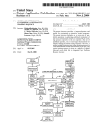
In the following example, you select the controller address, the type of download, the
program file to download, and the items to be saved. You choose the OK command
button to begin downloading.
Daikin
Page 20
Selecting an Active Window or Dialog Box
When multiple windows (user screens and/or dialog boxes) are open, changes will only
be allowed in a single window at any one time. This is the active window. Some dialog
boxes are restricted to always be active when opened and not allow other Monitor
functions to operate until they are closed. Others allow for manually selecting the active
window.
To select a window to be active position, the selection cursor over a portion of that
window and click the left hand mouse button. There is a manual keystroke alternative
that applies to user screens only. Type Ctrl+F6 to switch between open user screens.
Daikin
Page 21
Daikin
Page 22
Part 2 Working with Monitor
Menu Structure ........................................................................................................ 23
Chapter 4 - File and Screen Menus......................................................................... 25
Exit ......................................................................................................................... 25
Monitor Unit........................................................................................................... 25
Monitor Group........................................................................................................ 28
Previous Unit F5 / Next Unit F6 .................................................................. 33
Copy Ctrl +C ...................................................................................................... 33
Print ........................................................................................................................ 34
Show Main Screen ................................................................................................. 35
Chapter 5 - Comm Menu......................................................................................... 36
Connect................................................................................................................... 36
Disconnect.............................................................................................................. 38
Network Diagnostics .............................................................................................. 39
Chapter 6 - DataLog Menu ..................................................................................... 42
Trend Logging........................................................................................................ 42
Setup Trends........................................................................................................... 42
View Trends ........................................................................................................... 45
Setup Graphs .......................................................................................................... 46
Graph Trends.......................................................................................................... 47
Copy DDE Link ..................................................................................................... 47
View Alarms........................................................................................................... 48
Setup Alarms/Events .............................................................................................. 49
Chapter 7 - Support Menu ...................................................................................... 51
Read/Write ............................................................................................................. 51
Download ............................................................................................................... 54
Show Data File ....................................................................................................... 60
Network Passwords ................................................................................................ 60
User Passwords ...................................................................................................... 62
Log-out ................................................................................................................... 64
Set Controller Clock............................................................................................... 64
General Setup ......................................................................................................... 65
Chapter 8 - Window Menu ...................................................................................... 69
Cascade................................................................................................................... 69
Tile Horizontal/Tile Vertical .................................................................................. 69
Arrange Icons ......................................................................................................... 69
Open Windows....................................................................................................... 70
Chapter 9 - Help Menu .................................................Error! Bookmark not defined.
Help on MicroTech Monitor .................................................................................. 71
Help on Application #x .......................................................................................... 72
Help on YOURJOB................................................................................................ 72
About MicroTech Monitor ..................................................................................... 74
Menu Structure
Monitor is run by using the command options found in the pull-down menus or by
using the command buttons programmed into the viewing screens. The command
options are accessed by clicking on one of the menu names from the menu bar. The
following menus are available:
File
Screen
Comm
DataLog
Support
Window
Help
Once a menu has been opened, a list of command options are displayed. By moving the
selection cursor to the option of your choice and clicking with the left mouse button the
option is selected.
Options with the “...” (ellipsis) extension will open up a dialog box.
Options with the “
" extension will open up an additional choice of options.
Options without an extension will execute the selected command.
Daikin
Page 24
Chapter 4 - File and Screen Menus
Within the File menu is the following command option.
Exit
Within the Screen menu are the following command options.
Monitor Unit ...
F2
Monitor Group ... F3
Previous Unit
F5
Next Unit
F6
Copy
Ctrl+C
Print...
Show Main Screen
Exit
Exit will initiate exiting from Monitor. The following dialog box will appear
confirming your intentions. If OK is chosen, Monitor will end and you will be returned
to the Windows Program Manager. If Cancel is chosen, Monitor will resume.
Monitor Unit
Monitor Unit allows the user to choose a unit they wish to view. By selecting this
option, the user is given a dialog box titled "Controller List". The "Controller List"
provides information that is common to every unit. To Select a unit to monitor either
type in the Controller Label or highlight your choice by pointing to it with the mouse
and clicking. Then either click on Choose or press the <ENTER> key.
.
Daikin
Page 25
For each controller the following data is displayed.
Controller Information
Label
Description
Address
Unit Type
Description
A Label is a name given to each unit for selecting and identifying it as part
of a network. It must be unique for each unit in order to differentiate
between all others. A Label is restricted to an 8 character length.
A Description is used to describe the controller in more detail than the label.
It does not have to be unique. It is limited to a 30 character length.
Each MicroTech controller has an assigned address when it is part of a
network or operating in a stand alone environment. This address
differentiates it from other controllers and is used by Monitor as a unique
locator for communications purposes. Refer to Appendix D, Network
Architecture and Addressing.
The Unit Type is a designator for Monitor. It is used to identify common
characteristics between controllers in order to assign the correct application
screens and to determine the appropriate alarm label when using the Alarm
Logging feature.
The following command buttons are associated with the "Controller List" dialog box.
Command Button
OK
Add
Edit
Delete
Close
Description
Use this button to open the windows associated with the chosen controller.
Use this button to open a dialog box used to add an additional controller.
Use this button to change information about any listed controller.
Use this button to delete selected controllers from the Controller List.
Use this button to close the Controller List dialog box.
When Add is chosen, the following dialog box appears. Type in the appropriate
information for Address, Label, and Description and select the Unit Type and Screen
Name from the drop-down lists, then choose OK. To cancel the add process at any
point, choose Cancel.
Daikin
Page 26
When Edit is chosen, the following dialog box will open. Make any changes by typing
in the information for Address, Label, and Description and change the Unit Type or
Screen Name from the drop-down lists, then choose OK. To cancel the add process at
any point, choose Cancel.
Select any unit in the Controller List. When Delete is chosen a verification dialog box
will open.
Choose OK to proceed with deleting the unit. To cancel the deletion choose Cancel.
Daikin
Page 27
Monitor Group
Monitor Group allows the user to set up, save, and retrieve information from selected
groups of controllers and user selected parameters within controller types. From the
group monitoring screen, you are allowed to change the values of setpoints in single and
multiple controllers of the same type. You can also choose single units for immediate
viewing.
By selecting this option the "Group Monitoring and Report Generation" dialog box is
displayed.
Group Monitoring and Report Generation.
The following can be performed from the "Group Monitoring and Report Generation"
dialog box.
Dialog Box Field
Defined Groups
Edit Group
Delete Group
New Group
View...
Report...
Cancel
Daikin
Description
Select any group displayed by positioning the selection cursor and clicking with
the left mouse button.
Allows the editing of the information of a previously defined group that has been
selected.. Opens up the Setup Group dialog box
Deletes any selected group.
Allows creating a new group. Opens up the Setup Group dialog box.
Opens up a Group Monitoring window displaying information about the
selected group.
Opens up a "Select File" dialog box to select a file used store a snapshot of the
selected group's current data information. A new file may be typed in with a
CSV extension or an existing file may be selected and overwritten. Choose OK
from the "Select File" dialog box to copy current data information into the file. A
dialog box showing the report generation status appears for an instant of time.
Closes the dialog box.
Page 28
New Group and Edit Group
New Group and Edit Group functions are similar. The function allows the user to name
the group, select variables to include into the group, and select from a list of available
controllers. Choosing either will open up the "Setup Group" dialog box.
These options allow the setup for group monitoring.
Dialog Box Field
Description
Data Points
Selected Units
OK
Cancel
Description
Type in a unique name used to describe the group.
Choose Add to create or modify a list of data point variables for monitoring .
Choose Delete to erase all selected data points.
Choose Add to add to or subtract from the list of monitored units.
Choose Delete to erase units from the list of monitored units.
Accepts all current changes to the group information and closes the dialog box.
Ignores all current changes to the group information and close the dialog box.
Choosing Add in the Data Points field will open up the "Variables for:" dialog box.
Daikin
Page 29
Open one or more of the user screens for an individual unit and position the selection
cursor over the data point that you desire adding to the list. The selection cursor should
change from the normal
to the
symbol. Click on the left mouse button to select
the data point. Each selected data point will be added to the list of variables. There is no
limit to the number of data points that may be selected.
Choose OK to accept the list and return to the "Setup Group" dialog box, select any
variable(s) from the list and choose Delete to erase them , or choose Cancel to erase all
newly added variables and return to the "Setup Group" dialog box.
Daikin
Page 30
When returning to the "Setup Group" dialog box, the units whose screens were accessed
when selecting data points are displayed in the Selected Units field. Choosing Add in
the Data Points field will open up the "Select Units for:" dialog box.
Select additional units that you want to monitor from the List of Units field and transfer
them to the List of monitored Units field or visa versa. You may also select to transfer
all units into either list. Choose OK to accept all changes and return to the "Setup
Group" dialog box. Choose Cancel to erase all changes and return to the "Setup Group"
dialog box.
Daikin
Page 31
Choose OK or Cancel as described above to return to the "Group Monitoring and
Report Generation" dialog box..
Viewing a Selected Group
Select a group and choose View. A group screen will be created to display all of the
selected information for the selected units. Note that only selected units that have
corresponding selected data points will be displayed.
Unit Type
Daikin
Controller
Label
Variable
Label
Data
Page 32
Additional control features are available.
View Screen Feature
Unit Type
Controller Label
Variable Label
Data
Description
Identifies name for a group of common units.
Position the selection cursor over the controller label. Double-click with the left
mouse button to open the user screens associated with the selected controller.
The original label for a data point can be difficult to interpret. Changing the label
will make it easily understandable by the user. (Example; the original label
"RmTRam" can be replaced with "Room Temperature"). Position the selection
cursor over the variable label. Double click with the left mouse button to open the
"Question" dialog box to change the variable label from its original form.
Position the selection cursor over the data point. If the variable is changeable the
selection cursor should change from the normal "" to the "" symbol. Click on the
left mouse button to open the "Change Value" dialog box.
Previous Unit
F5 / Next Unit
F6
Previous Unit and Next Unit allow navigation through the controller list in either the
forward or reversed direction. The intent of this command option is to provide the
shortcut keystrokes of the F5 and F6 function keys in place of a mouse driven point and
choose operation. The function will wrap around to the first or last unit depending upon
the direction of the scrolling. Only the opening screen for the unit will be displayed.
Viewing additional screens is limited to a mouse driven operation.
Copy
Ctrl +C
Copy allows you to copy a full screen or displayed window of a monitoring image or
data log graph to the clipboard so that it can be used by another windows' application. If
an application screen is sized, only the visible portion of the active window will be
copied. Maximize the window if you desire the full image to be copied.
Clicking on this option will result in the replacement of the normal
symbol as the selection cursor.
with a
The selection cursor should be moved to any portion of the screen area that is to be
copied. Then click the left mouse button to send the image to the clipboard. If the
selection cursor is positioned inside a dialog box or within a bar the following message
will be displayed and no image will be copied.
Daikin
Page 33
Print
Print will print a selected screen to a connected printer. All values within the displayed
portion of an active window will be printed including title, command, and status bars. If
the selected application screen is sized, only the portion of the window that is visibly
displayed will be printed. Maximize the window in order to print the entire image.
Clicking on this option will result in the replacement of the normal
symbol as the selection cursor.
with a
The selection cursor should be moved to any portion of a displayed window that is to be
printed. Then click the left mouse button to send the image to the printer. If the selection
cursor is positioned inside a dialog box or within a bar, the following message will be
displayed and no image will be printed.
If the selection is valid, a small window will appear to inform you of the printing
progress. When the printing is completed the window will vanish.
If you choose Cancel within the printing progress dialog box, an "Error" message
window might appear indicating a failure to complete the printing process. Choose OK
to close this window and continue.
Daikin
Page 34
Show Main Screen
Show Main Screen chooses and opens the "main screen" window. The main screen is
the first screen a user will see when they enter Monitor. It has no command buttons and
will display minimal job information.
The main screen graphic is contained in a Windows Metafile Formatted (*.WMF) file
that is named MAINSCRN.WMF. This file may be replaced with any *.WMF file that
is renamed MAINSCRN.WMF and placed in the subdirectory operating the job
configuration for Monitor. This allows the user to insert a customized graphic into their
Monitor application.
Daikin
Page 35
Chapter 5 - Comm Menu
Within the Comm menu are the following command options.
Connect...
Disconnect...
Network Diagnostics...
Connect
Connect will initiate a communication attempt using the setup parameters defined
through the "General Setup Parameters" dialog box of the General Setup command
option of the Support Menu.
Depending on whether the communications is setup for DIRECT or PHONE, the "Init
Comm" dialog box will open and a communications attempt will commence.
Connection to a controller either by phone modem or direct linkage requires a positive
response from the controller to the request made by Monitor. The request from
Monitor includes an 8 character hexadecimal password that is used to prevent
unauthorized communication. The password used in the connection attempt must be
accepted by the controller. Monitor will use the Comm Password and/or some alternate
pre-defined passwords. The Comm Password is selected in the "General Setup
Parameters" dialog box of the General Setup command option of the Support Menu and
is displayed and available for change to Daikin factory trained users only.
Daikin
Page 36
For DIRECT connection attempts, the requests from Monitor are made at different
transmission speeds (baud rates). For PHONE modem connection attempts, the baud
rate is determined by that between the sending and receiving modems. In either case the
baud rate of the request must match the baud rate assigned to the linked controller's
communications port.
Failure to Connect
If either the password or the baud rate are not accepted by the linked controller a
connection is not established.
Choose Retry to attempt to connect again using the same setup parameters. Choose
Cancel to close the dialog box without connecting. Choose Change Setup to open the
"General Setup Parameters" dialog box to change any of the setup information (see
General Setup).
Successful Connection
If the password and the baud rate are accepted by the linked controller, a positive
acknowledgment is received, a connection is established and the "Init Comm" dialog
box closes.
Daikin
Page 37
If an alternate password is used for connection a warning message dialog box is
displayed.
If Monitor is being linked to the level 1 controller for a network or a single unit
controller in a stand-alone application, this can indicate an improper setup of the
Monitor application. This may require a change to Monitor by a Daikin authorized
user. If Monitor is linked to a slave unit controller in a network for a
temporary connection, this can be a normal condition.
Disconnect
Disconnect will break the Monitor to controller communications connection. It will not
exit Monitor. If your type of connection was DIRECT, the status bar will display the
message "Port is not open". If the connection type is PHONE, the following message
box appears.
Daikin
Page 38
Network Diagnostics
Network Diagnostics opens up the "Network Diagnostic Parameter Setup". The
network diagnostic function is a tool for troubleshooting network communications
problems. Its basic use is to test each controller for communication to the front end
computer. It can be used in a more advanced interpretation to isolate communication
problems between two individual controllers.
The "Network Diagnostic Parameter Setup" dialog box is displayed when Network
Diagnostics is chosen. After completing the setup choose OK to initiate.
Performing the Setup
Daikin
Page 39
The "Network Diagnostic Parameter Setup" dialog box contains the following.
Dialog Box Field
Display Node
Display Mode
Diagnostic Option
Log Files for Errors
OK
Cancel
Description
Enter the address to identify the start of a chain or to identify a single controller.
Select one of the following:
• Chain - selects a chain of controllers. Monitor will scan the controller whose
address has been entered and its slaves and the slaves of its slaves (within
network architecture limitations).
• Single - selects only a single controller. Monitor will only scan the controller
whose address has been entered.
• Loop - select to continually loop through the chain of controllers or single
controller.
• One Pass - select to perform a single pass through the chain of controllers or
single controller.
• Show program ID - select to display the an identification string for the
application program that is loaded into the controller (6 characters for a model
1xx and 8 characters for a model 2xx controller).
• Show program status (OK, *Cksum, *Data) - select to display information
about the operation of the application program. A *Cksum will indicate a
corrupted program in both a model 1xx and 2xx controller. A *Data will indicate
a memory allocation error preventing the execution of a program in a model 2xx
controller. An OK indicates no problem with the application program.
• Restrict display of L3s to units with errors - select to reserve screen space for
controllers that require attention.
• Clear communication errors if found - select to clear the communication error
memory buffer in each controller while it is scanned. Further scans of the
controller will only display current communication errors if present.
Select an existing file or type in a new file name to log communication errors into
for future analysis.
Opens the "Network Diagnostics Status" dialog box and runs network diagnostics.
Closes the "Network Diagnostic Parameter Setup" dialog box without saving
changes.
Running the Network Diagnostics
The "Network Diagnostics Status" dialog box is displayed after choosing OK from the
"Network Diagnostic Parameter Setup" dialog box.
Daikin
Page 40
The following are in the "Network Diagnostic Status" dialog box..
Dialog Box Field
Display Area
(not labeled)
Current Info
Current Error
Retry
Skip String
Cancel
Daikin
Description
Provides a single line of data for each scanned controller. For a more detailed
description refer to Appendix C, "Communications Responses".
Provides information relating to the current scan. In a Loop selection the number
of pass will increase each time the entire network is scanned.
Provides a total summary of all errors that have been found during the current
Network Diagnostic session.
Commands the function to retry a pass. This is used during a single pass
selection.
This commands the function to skip all controllers within a string that are being
scanned. Use this to skip the diagnostic scan of either a level two or a level three
string of controllers.
This commands the Network Diagnostics function to stop if in the Loop scan
mode or closes the dialog box and returns you to setup if a single scan has been
completed or a Loop scan has been terminated by a previous Cancel.
Page 41
Chapter 6 - DataLog Menu
Within the DataLog menu are the following command options.
Setup Trends...
View Trends
Setup Graphs
Graph Trends
Copy DDE Link
View Alarms...
Setup Alarms/Events...
Trend Logging
Monitor allows any data-point to be trend-logged. Six groups of data-points may be
trend logged. Each group can have up to 16 data points to trend. The data-points in a
group can be taken from any screen and can access any controller in the network. The
data can be viewed graphically or in a tabular formatted form. In order to choose trend
log data points, Monitor must be connected to a network or controller. Trend log data
may be written to the disk as an ASCII file. To set up trend logging, communications
should have been established with the network. All the functions associated with trend
logging are available under the DataLog menu. View Trends, Setup Graphs, Graph
Trends, and Copy DDE Link rely on one or more of the six trend groups being active.
These menu options will be disabled if none of the groups are active..
When Monitor is performing trend logging, the message DLog appears on the status
bar each time a sample of data is acquired. If writing to disk has been specified, the
trend-log information is formatted into columns and written as an ASCII file with the
specified filename and extension .CSV. Note that a CSV (comma separated value)
format is commonly used for ASCII data exchange and is compatible with applications
such as MS Excel and Lotus. If a file by the specified name does not exist, a new file is
created otherwise, data is added to the existing file. Monitor enters the name of the
group and the time when data logging was started as header information in the file. Each
log entry begins with a PC time-stamp.
Setup Trends
Setup Trends allows the user to select variables within the defined HVAC application
windows and display those values in a tabular form or in a graph and/or store those
values in a file or into another Windows application through a DDE (Dynamic Data
Exchange) link. Trend logging can be either manually initiated or initiate based upon a
date/time schedule. Trend logging can only occur when the Monitor program is active,
either in a full screen or window mode or while minimized.
To set up trend logging, click on the DataLog / Setup Trends menu. The "Trend Setup"
dialog box is displayed.
Daikin
Page 42
The following fields are available for each of six groups..
Dialog Box Field
Group #x
Active
Edit...
OK
Cancel
Description
Contains the name for Group#x.
Check this box to activate the trend log.
Opens the "Trend Group #x Setup" dialog box for the selected group.
Accepts all current changes and closes the "Trend Setup" dialog box.
Ignores all current changes and closes the "Trend Setup" dialog box.
Choose Edit to open the "Trend Group #x Setup" dialog box for one of six groups.
Daikin
Page 43
The following fields are available within the "Trend Group #x Setup" dialog box.
Dialog Box Field
Description
Input File
Output File
Sampling Time
Time Triggered
Start Date and Time
Stop Date and Time
Variables
OK
Cancel
Description
Type in a unique name for the trend log group. Name may be up to 30 characters in
length.
Opens the "Select File" dialog box and either choose from an existing file list or type
in a new file name including a .TLG extension. This file is used to store the setup
information.
Opens the "Select File" dialog box and either choose from an existing file list or type
in a new file name including a .CSV extension. This file is used to store trend log
data .
Enter the frequency of the trend log sample.
Check this box if the trend log is to be confined to a specified date and time period.
If time triggered is checked enter date and time to begin trend log.
If time triggered is checked enter date and time to end trend log.
Opens the "Trend Group #x Variables" dialog box.
Accepts all current changes and closes the "Trend Group #x Setup" dialog box.
Ignores all current changes and closes the "Trend Group #x Setup" dialog box.
.
Choose Variables to open the "Trend Group #x Setup"
Open one or more of the user screens for the selected unit that contains the data point
variable(s) to be selected. Position the selection cursor over the data point. The selection
cursor should change from the normal
to the
symbol. Click on the left mouse
button to select the data point. Each selected data point will be added to the list of trend
variables. The data point will also include the controller label of the selected unit.
If the mouse is clicked on a data-point that is already in the list, the system beeps. The
system also beeps if 16 data-points have been specified for the current group and the
mouse is clicked on a new data-point. When Monitor has the "Trend Group#x
Variables" dialog box open, setpoints cannot be changed.
Delete any data-point from the list by selecting the data-point in the list box and
choosing Delete. Multiple data-points may be selected and deleted at once. Choose OK
to accept all current changes, close the "Trend Group #x Variables" dialog box, and
return to the "Trend Group #x Setup" dialog box. Choose Cancel to close the "Trend
Group #x Variables" dialog box dialog boxes without accepting changes and return to
the "Trend Group#x Variables" dialog box.
Daikin
Page 44
View Trends
When any trend-log group is active, View Trends is also active. When View Trends is
selected a list will appear to the right of the menu option. This list will display the name
of all of the open groups allowing one of them to be chosen.
Choose one of the group names to open the "View Trends" dialog display window.
The title of this window will be the name of the group. The window will contain the
trend log information and will display a history of the last 20 samples. Each data point
will have a column heading to identify each variable and associated controller. The time
that the sample was taken is also provided as the first element of each row.
This window may be moved and re-sized. The horizontal scroll bar may be used to
bring any part of the data into view. Only one trend-log group data may be viewed at a
time. To close the window, double-click on the control menu box at the top left-hand
side of the window. Close the current trend log window in order to open another group.
Daikin
Page 45
Setup Graphs
When any trend-log group is active, Setup Graphs is also active. When Setup Graphs is
selected a list will appear to the right of the menu option. This list will display the name
of all of the open groups allowing one of them to be chosen.
Choose one of the group names to open the "Setup Graphs" dialog display window.
The title of this window will be the name of the group. Setting up a graph consists of
choosing one of four available scales for each of up to sixteen data points and defining
parameters for each of the four scales.
The following fields are in the "Graph Setup" dialog box.
Dialog Box Field
Trendlog Variables
Scale
OK
Cancel
Show Date
Min
Max
Setpt1 / Setpt2
Label
Description
Lists the controller label and the variable name for up to sixteen variables.
Select any or none of the four available scales to be used as the vertical range
marking of the graph.
Choose to accept all current changes and to close the "Graph Setup" dialog box.
Choose to ignore all current changes and to close the "Graph Setup" dialog box.
Select this if the horizontal time scale is to also include the date.
Type in the minimum value of the range for each of four scales. Default = 0.
Type in the maximum value of the range for each of four scales. Default = 255.
Type in a value between the minimum and maximum range values to be used as a
setpoint marker line to be compared against the actual condition. You can create two
setpoint lines.
Type in a label name for each of the four scales.
This window may be moved and re-sized. The horizontal scroll bar may be used to
bring any part of the data into view. Only one trend-log group data may be viewed at a
time. To close the window, double-click on the control menu box at the top left-hand
side of the window. Close the current trend log window in order to open another group.
Daikin
Page 46
Graph Trends
When any trend-log group is active, Graph Trends is also active. When Graph Trends
is selected a list will appear to the right of the menu option. This list will display the
name of all of the open groups allowing one of them to be chosen.
Choose one of the group names to open the "View Graphs" dialog display window.
Only one graph can be viewed at a time. While the graph window is active, all other
Monitor functions like changing screens or changing setpoints can be done. The scales
and the variables that are being plotted can be changed at any time by going to the
"Graph Setup" dialog box. The window is updated to reflect the new setup.
.
Copy DDE Link
Dynamic Data Exchange (DDE) is a technique that links two applications running in the
Windows 3.1 environment allowing them to establish a one-way conversation for
updating similar data. It is an automation of the manual "cut and paste" operation. When
you choose Copy DDE Link for an active trend, Monitor becomes the "server" for a
DDE link. Any changes that occur in the trend data are made available to any "clients"
that are linked to the data. A "client" is an application that accepts and processes a DDE
link. For more information on DDE links consult Appendix D.
Daikin
Page 47
View Alarms
View Alarms provides a dynamic list of network alarms and status. A Network Master
Panel (NMP) must be installed in the network for this function to work properly.
There can be as many as 63 alarm records stored in the NMP for retrieval by Monitor.
When the storage space limit is exceeded, the NMP overwrites the oldest alarm in the
buffer and continues to do so when new alarms require logging. This maintains the most
recent alarms in the alarm buffer. Note that a separate alarm record is used when an
alarm is first logged and when it is cleared. As a result the View Alarms function can
display as many as 31 cleared alarms or 63 active alarms or a combination of less than
63 cleared and active alarms.
Choosing View Alarms will open the "Alarm Display" dialog box.
Each alarm message has the following format.
Alarm Message Item
Label
Message
Logged
Cleared
Unit
Ack
Description
Label descriptor of the controller the alarm is associated with. This is obtained by
matching the controller address with the first unit label that matches from the
controller unit list.
Appears as either an active or cleared message. Describes the alarm condition.
Provides the date and the time that the active alarm was logged by the NMP.
Provides the date and the time that the cleared alarm was logged by the NMP.
Provides the network address of the controller that the alarm occurred in.
If the alarm was acknowledged this will display the name of the user that
acknowledged it. If the alarm was acknowledged by a Daikin factory trained
user this will display "Yes". If the alarm has not been acknowledged this will
display "No".
The following command buttons are also available.
Dialog Box Field
Global Ack
Acknowledge
Clear Buffer
Cancel
Daikin
Description
Acknowledge all alarms that are in the alarm buffer of the NMP.
Acknowledge selected alarms only.
Clears the NMP alarm buffer and resets the Monitor alarm pointers. This will also
generate an event for the NMP.
Close the "Alarm Display" dialog box. Does not cancel alarm acknowledgment or
clearing the NMP alarm buffer.
Page 48
Setup Alarms/Events
Setup Alarms/Events will open the "Alarm/Event Setup" dialog box for defining the
parameters for alarm and event logging.
Daikin
Page 49
The dialog box is broken up into the fields, General, Alarm Logging, and Event
Logging with two additional command buttons.
Dialog Box Field
General
Alarm Logging
Event Logging
OK
Cancel
Description
• Direct Logging - select to enable the "direct logging" mode. Refer to
Appendix B.
• Remote Logging - select to enable the "remote logging " mode. Refer to
Appendix B.
• Enable Alarm Logging - check this box to enable the alarm logging feature
of Monitor. Upon initialization the alarm buffer in the NMP will be read to
display all current alarm conditions. Every 15 seconds thereafter Monitor
will read the NMP to check for new alarms and display them as needed.
During that time a Dlog message will appear in the status bar delaying any
response to keypad or mouse activity. Whenever a new alarm is received a
message dialog box will occur asking if you want to view the alarms now.
Checking this box will also enable access to the following features.
• Record Alarms on Printer - check this box to record new alarms as they
occur onto the line printer as defined in the "General Setup Parameters"
dialog box of the Support menu's General Setup command option.
• Record Alarms on Fax - check this box to send out new alarms as they
occur using a data fax format as defined in the "General Setup Parameters"
dialog box of the Support menu's General Setup command option
• Save Alarms to File - check this box to record new alarms as they occur into
a designated file.
• File - type in the name of the designated file used for storing alarms.
• Annunciate Alarm - check this box to continuously annunciate
unacknowledged alarm. A menu heading by the name "Alarm" will appear
between the Support and Window menu . Every ten seconds the background
color of this menu will toggle between green and red. An audible beep will
also occur every ten seconds.
• Enable Event Logging - check this box to enable the event logging feature
of Monitor. Checking this box will also enable access to the following
features. Refer to Appendix B for further details.
• Record Events on Printer - check this box to record new events as they
occur onto the line printer as defined in the "General Setup Parameters"
dialog box of the Support menu's General Setup command option.
• Record Events on Fax - check this box to send out new events as they occur
using a data fax format as defined in the "General Setup Parameters" dialog
box of the Support menu's General Setup command option
• Save Events to File - check this box to record new events as they occur into
a designated file.
• File - type in the name of the designated file used for storing events.
Accepts all current changes and closes the "Alarm/Event Setup" dialog box.
Ignores all current changes and closes the "Alarm/Event Setup" dialog box.
When new alarms occur the following dialog box is displayed provided that Alarm
Logging has been enabled.
Chose Yes to open the "Alarm Display" dialog box. Choose No to close this message
box without any action.
Daikin
Page 50
Chapter 7 - Support Menu
Within the Support menu are the following command options.
Read/Write...
Download...
Show Data File...
Network Passwords...
User Passwords...
Log-out...
Set Controller Clock...
General Setup...
Read/Write
Read/Write will open up the "Read/Write Screen." This gives the capability to view
and/or alter data from absolute memory addresses within any MicroTech controller.
This function is only accessible to a User that is at an Authorization Level of one or to
any Daikin Factory trained user. This function should only be used by persons who
have been directed to by Daikin or by persons who know the significance of the
memory addresses as they relate to the controller and to the application program. The
disclosure of memory addresses is controlled by Daikin.
Daikin
Page 51
The "Read/Write Screen" contains five information fields. These are the Operation,
Display, Address, Status, and the data field.
Dialog Box Field
Operation
Display
Address
Status
Data
Description
This field contains the Read and Monitor options buttons. If Read is selected
the data is read in one pass. Once the data is read the display becomes idle. To
re-read the data choose the OK command button. If Monitor is chosen the
selected data is read in a continuous loop. As the information is continuously
read, any updated data is displayed.
This field contains three option buttons. This determines in what format the
data will be displayed. and written into selected memory locations. Select either
hexadecimal, decimal, or ASCII (American Standard Code for Information
Interchange, a standard used for converting a byte of hexadecimal data into
alphanumeric characters.).
This field has two sections, that of the memory address and of the controller
address. The data address may be of a single memory location or a range of
locations up to 99 characters. It should be entered using one of the acceptable
formats as described in Appendix C. The controller address may be that of
single controller or a range of controllers up to 99 characters. It should be
entered using one of the acceptable formats as described in Appendix C. It will
accept up to 99 characters.
Displays the status of the Read/Write operation.
Displays the requested data in the appropriate display format. This field has a
vertical scroll bar which allows specifying memory ranges that will not fit in a
single window. The data window has the capacity of displaying 4 rows of 16
elements each.
The following command buttons are also available.
Dialog Box Field
OK
Cancel
Stop Write
Description
Choose OK to accept changes made in the Address field or to re-scan the data for a
Read operation.
Choose Cancel to close the Read-Write Screen and disregard any changes made to the
Address field prior to choosing OK.
Choose Stop Write when doing a Global or Partial write to stop the write at the point
Monitor is at. Monitor will not rewrite to memory locations already written to.
How to Write Data to a Memory Location
To write data, simply move the selection cursor within the data field to the value you
wish to change and click the left mouse button. The data will become a small dialog box
with a text box field and two small command buttons labeled N and Y. Use the text box
to enter the desired value in hexadecimal, decimal, or ASCII depending upon the
selected format.
Daikin
Page 52
Once the text is entered chose Y to write the change to the controller or N to cancel the
write before its performed. Choosing Y will open the "Write to Controller" dialog box.
The "Write to Controller" dialog box has the following options.
Option
Single
Partial
Global
Cancel
Description
Allows a write to the selected controller and memory location only.
Allows a write to single selected memory locations in all selected controllers.
Allows writing to all selected memory locations in all selected controllers.
Cancels the write and closes the dialog box.
Note: A write to multiple controllers and/or multiple memory locations may be stopped
by choosing the Stop Write command button. This will only stop the process where it is
and will not reset memory locations that have been written to back to their previous
values.
Daikin
Page 53
Download
Download either downloads application code into and/or restores previously saved data
into or uploads application code from or saves selected data from a MicroTech
controller.
Downloading application code requires knowing controller addresses, program file
names, and the effects of upgrading codes from previous versions to determine what
parameters can and/or should be saved and restored. This information will be provided
during a job start-up as part of the software release form and/or through an on-line
accessible help file. Whenever a software upgrade is required, this information will also
be made available. Both downloading and restoring data will interrupt the operation of a
MicroTech controller and should only be done when necessary or bringing the unit
down is compensated for.
Uploading requires knowing the controller address only. Uploading will not affect the
operation of a controller and can be done at any time. The file name to upload into is
selected by the user and is used for unique identification of data records only.
Choosing Download opens the "Download/Save/Restore Controller" dialog box.
Daikin
Page 54
The "Download/Save/Restore Controller" dialog box contains five information fields.
These are Controller Address, Download Options (unlabelled), Program File, Data File,
and Save Options and include two additional command buttons.
Dialog Box Field
Controller Address
Download Options
Program File
Data File
Save Options
OK
Cancel
Daikin
Description
Data entry into this field conforms with the standard entry format described in
Appendix 3 (Network Architecture and Addressing) with one exception. Entering a *
will allow saving, restoring, or uploading from every controller on the network.
This field contains five option buttons used to select the function option. Additional
fields will be enabled for entry or selection depending upon the selected option as
described below:
• Download Program to Controller; performs the downloading of file *.cod
selected without saving or restoring any current information contained in the
controller. Enables "Program File".
• Save Data, Download Program, Restore Data; saves selected current data,
performs download, then restores the saved information as one operation. Enables
"Program File", "DataFile" and "Save Options".
• Save Controller Data to File; saves selected information for archival purposes.
Enables "Data File" and "Save Options".
• Restore Controller Data from File; restores previously saved data. Enables
"Data File" only.
• Upload from Controller (Saves Everything); in addition to saving all standard
data will save the application program in selected controllers. Enables "Data File"
only.
Choose the Program File command button to open up the "Open EPL Code File"
dialog box from which the correct *.COD file is selected to be downloaded or type
the file name and path (if not the current path) into the edit control box directly.
Choose the Data File command button to open up the "Open Controller Data File"
dialog box from which file name header is selected to save data in or type the file
name and path (if not the current path) into the edit control box directly. The
Download function will modify the file name so that the last two characters before
the period and the first two characters of the extension will comprise the network
address for the controller that information is being saved from.
Use the check boxes in this field to select the type of data that will be stored during a
save operation.
• All Standard Data; will save Setpoints, Control Variables, Tables, Port
Configurations, and Passwords. If this option is selected it will clear any other
checked box.
• Setpoints; will save only data stored as setpoint variables beginning with memory
location $0900.
• Control Variables; will save only data stored as control variables beginning a
memory address $0800.
• Tables; will save only data stored in tabular arrays beginning at memory location
$1000.
• Port Configuration; will save the data necessary for setting up the
communications ports on the MicroTech controller including baud rate, network
level, and number of designated slaves.
• Passwords; will save the data terminal connect passwords that restrict
unauthorized communication with a MicroTech controller.
• Specific Addresses; use this to designate specific memory addresses to be saved.
This requires advanced knowledge of memory locations or specific downloading
instructions.
Choose OK to accept changes and begin the download /upload process
Choose Cancel to close the "Download/Save/Restore Controller" window.
Page 55
Once all of the set-up information is completed, choose OK to begin the download
process.
The download process begins by requesting verification of the controllers to be used. If
any mistake is realized at this point simply choose Cancel to return to the previous
dialog box.
If OK is chosen, Monitor will attempt to communicate with each listed controller. At
this point, the Skip Unit and Cancel command buttons are available to choose. If you
are aware of any problems with the ability to communicate with the displayed
controller, choosing Skip Unit will bypass checking that unit. If there are multiple units,
Monitor will move to the next unit in the list.
Daikin
Page 56
If communications problems occur while checking a controller the Retry command
button becomes available. The choices available at this point are Retry, Skip Unit, and
Cancel.
Daikin
Page 57
If communications are successful, Monitor begins by saving data from the controller.
Cancel is the only command button available at this time.
Once the save process is completed, Monitor will deactivate the current application
code running in the selected controllers by corrupting program checksums and restarting
each controller. This insures that no outputs are on while downloading new application
code or settings. Cancel is the only command button available at this time.
Once the program is deactivated, Monitor begins writing the new code into one or more
controllers. Cancel is the only command button available at this time.
Daikin
Page 58
After downloading of new code is complete, Monitor restores the data (if any ) that was
saved. Cancel is the only command button available at this time
After all of the new code has been downloaded to each controller and/or the saved data
has been restored, Monitor asks if it should restart controllers. Choose OK to restart
each controller or Cancel to end download without restarting the controllers.
If OK is chosen, Monitor will attempt to restart each controller. If the download was to
a directly connected unit, Monitor will first restart the unit, then re-establish a
connection to the unit (baud rate and password), and then restart the controller again.
Cancel is the only command button available at this time
Daikin
Page 59
Monitor reads the checksums in the unit to verify the success of the download. A final
dialog box appears if the download process was properly completed.
Show Data File
Show Data File uses the pre-defined Open File dialog box to choose a file for viewing.
This function is for viewing trend-logged data files but may be used to view any text
file. Once the file is chosen, a data window equipped with scroll bars (if necessary) will
display the contents of the file. This data window will have the characteristics of a
dialog box and will include a control-menu box.
This function is used to view the data files created by Monitor:
Data File Type
*.CSV
*.LOG
*.CHG
Description
Comma separated value format used to store data from the trend-log and group screen
report functions.
Used to store data collected during network diagnostics.
Used to store any changes made (writes) by a user to any value while in an application
screen.
Network Passwords
Network Passwords command option is restricted to Daikin factory trained users.
This option will be grayed out to all untrained users.
Choosing this option provides a utility to change the access passwords contained in a
MicroTech controller. To enable the options contained in the dialog box, it is first
necessary to enter the Level 1 password that Monitor is directly communicating with.
Daikin
Page 60
The next step is to enter the network address for the controller that a password change is
to be requested. The password level is then selected from the option buttons. Finally the
new password is entered. Note: a legitimate password consists of eight hexadecimal
characters.
Choose Cancel to close the dialog box without any changes taking place. Choose OK to
proceed with changing the password. A dialog box will appear requesting confirmation
of the intended change. Choose No to close that dialog box and return to the "Change
Network Passwords" dialog box to make changes. Choose Yes to proceed with the
change. The change will either be successful or not.
Daikin
Page 61
If successful you will be requested to change another password level. Choosing Yes will
return you to the Change Network Passwords dialog box to select another password
level and /or new password. Proceed as before. If you choose No, you will be requested
to restart the controller to assure that the program checksums are not corrupted.
Choose Yes to insure that the program in the controller will be running after leaving this
function. Monitor will restart the controller and indicate the status of the checksums by
a dialog box with the text that simply reads “Done”. Choosing No will generate a
warning that checksum may be invalid.
The status of changing the password will be displayed in the parent dialog box .If
unsuccessful the reason will be displayed. You may either make appropriate changes to
the setup and choose OK or choose Cancel to leave this command option.
User Passwords
User Passwords allows the building operator to set-up, alter, and view users allowed
access into Monitor. Only a user with authorization as high as level one can access this
function. Selected functions and setpoints within Monitor have been defined for use by
persons with different levels of authorization. This is to protect against unauthorized
changes to the HVAC equipment.
Daikin
Page 62
Select the Display Passwords check box to enable adding new users.
Type in the appropriate information and choose OK to accept.
Field Label
Log-in ID
Password
User Name
Auth Level
Auto
Log-out
Last Log-in
Last Log-out
Description
A character string used to identify the user to Monitor. It can be as long as will fit in the
space provided (recommend a short name of six characters or less). Combining the Log-in
ID and the password provides entry to Monitor.
A character string used to identify the user to Monitor. It can be as long as will fit in the
space provided (recommend a short name of six characters or less). Combining the
password and the Log-in ID provides entry to Monitor.
A character string that describes the user to the operator (level one user). This can be up to
20 characters long. including spaces.
A number defining the level of authorization. Anything below level 1 (levels 2..255) are not
allowed access to the Read/Write, Download, and User Password command options.
A time value, in minutes, that will cause the automatic log-out of a user if there is no user
activity within Monitor. Once logged out the user may re-enter or exit Monitor.
Records the time and date of the last log-in for that user.
Records that time and date of the last log-out for that user.
When choosing Add Entry, Monitor will provide default Log-in ID, password, Auth
Level, and Auto Log-out values of NEWUSER, NEWUSER, 1, and 0. Type over the
information provided in order to change it.
Daikin
Page 63
Log-out
Log-out will log out the user while allowing Monitor to continue to run in the
background. Any data logging functions will remain active at this time. If an event
occurs requiring action the user will be notified through a pop-up dialog box. This has
the same effect of minimizing Monitor except that restoring the application requires a
Log-in name and password.
Once logged out, the user can either log-in using the same or different user information
or exit Monitor.
Set Controller Clock
Set Controller Clock provides an automatic reset of the calendar/clock in any
MicroTech controller. The information that defines the date and time for the P.C. that is
running Monitor is transferred into the selected controller. Type in the controller’s
network address or a range of addresses and choose OK. Choose Cancel to terminate
the changing process. Once completed, Cancel will change to Exit. Choose Exit to
close the dialog box.
Daikin
Page 64
General Setup
General Setup will open the "General Setup Parameters" dialog box.
Daikin
Page 65
Options affecting Communication
The options that are available allow the complete setup of communications parameters
for Monitor to allow both direct and telephone connection.
Dialog Box Field
Monitor Title
Communications Parameters
Modem/Fax
Fax Test
Init Comm
OK
Cancel
Daikin
Description
Type in a new Monitor name or select a previously defined one from a
pulldown list. Name must be unique and is limited to xxxx characters.
Choose Delete to erase the parameters of a selected Monitor title group.
Select parameters for DIRECT or PHONE connection to a MicroTech
controller.
• Comm Port - Choose COM1, COM2, COM3, or COM4 for direct serial
communications. Refer to the hardware setup of the PC to determine the
proper serial port assignment.
• Comm Password - Appears in hidden form except for Daikin
factory trained users. Used for initial communications attempt by
Monitor.
• Timeout - The amount of time in seconds that Monitor waits before
indicating a comm problem with any controller
• Retries - The number of elapsed timeouts after a comm problem is found
before indicating a no response with any controller.
• Phone Number - Enter the phone number dialing string for telephone
communications. This may include any special characters allowed by the
modem being used. Refer to the documentation provided with the modem.
• Connection Type - Select either DIRECT or PHONE for type of
communications.
• DIRECT Baud Rate - Select the initial baud rate to be used for DIRECT
connection attempts. Note that all listed baud rates will be attempted
unless a connection is made.
• PHONE Baud Rate - Select the baud rate to be used for the modem
connection. This baud rate must match that of the MicroTech controller
that you are attempting to connect with.
• Auto Hangup - Amount of time in minutes to terminate a telephone
connection after there has been no user activity in Monitor.
Open the "Modem/Fax Settings" dialog box for setup of the modem and fax
requirements.
Send out a test message to all recipients defined in the "Modem/Fax
Settings" dialog box. The test message is made available for modification
before it is sent. It can be up to 79 characters in length.
Save all current changes and initiate a communications attempt.
Save all changes and close the dialog box.
Erase all changes and close the dialog box.
Page 66
When you choose Modem/Fax, the "Modem/Fax Settings" dialog box is opened.
The following information is contained within the "Modem/Fax Settings" dialog box.
Dialog Box Field
Initialize Modem
Dialing Prefix
Connect Code
Timeout (seconds)
Speaker Volume
Fax Driver
Recipient List
Defaults
OK
Cancel
Daikin
Description
Enter or modify any field initialization commands for the modem to be used before
initiating a telephone call. Refer to the technical documentation provided with the
modem. Monitor requires minimum requirements of:
E1 - Local echo enabled (set by Monitor automatically)
Q0 - Display result codes
V1 - Display codes in verbal format
X4 - Advanced set of response codes to enhance Monitor's responsiveness.
Enter the modem command prefix to be used directly before the phone number.
ATDT - Tone (Touch-Tone) dialing
ATDP - Pulse (rotary) dialing
The connection string sent by the modem to Monitor to indicate a successful modem
to modem connection.
Amount of time that Monitor waits for a response from its linked controller after the
modem to modem connection is established.
Set the speaker volume on the modem for the user's preference.
Assign the WinFax Pro 4.0 driver as the specific printer selection. (Requires WinFax
Pro 4.0 by Delrina.) Choose Fax Driver to open the "Print Setup" dialog box.
Allows you to create and modify a list of up to eight fax recipients.
Choose Add to open the "Add Fax Destination" dialog box.
Select a recipient from the list and choose Edit to open the "Edit Fax Destination"
dialog box.
Select a recipient from the list and choose Delete to erase the recipient information.
Will re-assign the factory defaults for the Initialize Modem, Dialing Prefix, Connect
Code, and Timeout fields.
Accepts all current changes and closes the dialog box.
Ignores all current changes and closes the dialog box.
Page 67
When Add is chosen, the "Add Fax Destination" dialog box is displayed.
Fill in the fax number and name of recipient. Choose OK to close the dialog box and
accept all current changes or Cancel to close dialog box without accepting changes.
When Edit is chosen, the "Edit Fax Destination" dialog box is displayed.
Fill in the fax number and name of recipient. Choose OK to close the dialog box and
accept all current changes or Cancel to close the dialog box without accepting changes.
Line Printer Options
Additional options allow setup of the line printer and file location and retrieval
parameters.
Dialog Box Field
Line Printer Parameters
Daikin
Description
Assign parameters for setting up the printer for on-line record keeping.
• Line Printer Port - Select either LPT1,2,3, or 4 for parallel printer
connection Refer to the hardware setup of the PC to determine the proper
parallel port assignment.
• Printer Control String - Type in initialization string , if necessary,
provided with your printer's documentation.
• Lines per page - Set the maximum lines to be printed per page.
Page 68
Chapter 8 - Window Menu
Within the Window menu are the following command options.
Cascade
Tile Horizontal
Tile Vertical
Arrange Icons
1 First Open Window
2 Second Open Window
3 Third Open Window
4 Fourth Open Window
5 Fifth Open Window
6 Sixth Open Window
7 Seventh Open Window
8 Eight Open Window
9 Ninth Open Window
More Windows
The Window menu provides a means to display and retrieve multiple open application
screen and group screen windows. You can use the cascade and tile command options to
rearrange application and group screens so that all open windows are visible in the
screen area. These commands will only work with open windows that are maximized or
sized.
Cascade
Cascade causes windows to overlap so that their title bars are all visible. You can then
select any application or group screen and make it active, maximize it, re-size it, or
minimize it.
Tile Horizontal/Tile Vertical
Tile Horizontal and Tile Vertical causes the windows to be arranged either horizontally
or vertically. This allow the user to close or minimize unwanted windows, maximize a
single window, or arrange and re-size multiple windows.
Arrange Icons
When open windows are minimized they are displayed as icons. Arrange Icons will
arrange the icons in order from left to right at the bottom of the screen area. This
function is only used with Windows 3.X.
Daikin
Page 69
Open Windows
What follows in the menu is a list of open windows with a check mark to the left of the
currently active window. The list is ordered by the sequence in which the windows were
opened. Simply choose the window that you wish to view. If the window is minimized it
will resume the form it was in when it became minimized (sized or maximized). The list
will be limited to last four application screens that had been opened and an unlimited
number of open group screens.
When the list exceeds nine open windows, the ninth selection is that of the last window
that was opened. The tenth selection displays More Windows. When More Windows is
selected the "Select Window" dialog box is opened. This contains a pulldown listbox
and a vertical scroll bar for selecting the desired window to view.
Daikin
Page 70
Chapter 9 - Help Menu
Within the Help menu are the following command options.
Help on Monitor...
Help on Application #1
Help on Application #2
Help on Application #3...
Help on YOURJOB...
About Monitor...
Help on MicroTech Monitor
Help on MicroTech Monitor opens the user up to an on-line help facility which is
essentially this user’s manual. The help utility uses the basic Windows format for
navigation and selection. A complete on-line manual on how to use Help is available
within Help. Simply choose the How to Use Help from the Help menu of the Help on
MicroTech Monitor of Monitor.
The following example shows the command buttons that are available from a help
screen. Additional navigation is made possible by choosing key-words that are found
within the text.
Daikin
Page 71
Help on Application #x
For each HVAC application there will be provided specific on-line help text. To access
this follow the instructions given above for Help on MicroTech Monitor.
Help on YOURJOB
Every software package release will be provided with a help file that is specific to that
particular job.
Selecting this option will open the "Job Specific Information" dialog box. This will
appear in top right region of the desktop.
Daikin
Page 72
This will contain information relating to the Job History, the Equipment List, and any
notes that the user wishes to maintain with the job. Selecting any of these is
accomplished by positioning the selection cursor over the appropriate icon and clicking
symbol
with the left mouse button. The normal cursor symbol will change to a
whenever you are over an appropriate icon.
Daikin
Page 73
About MicroTech Monitor
About MicroTech Monitor will display the "About MicroTech Monitor" dialog box
that gives information about your copy of Monitor including the version number; and
the copyright, legal, and licensing notices.
Daikin
Page 74
Daikin
Page 75
Appendix
Appendix A ............................................................................................................... 77
Communications Errors.......................................................................................... 77
Appendix B................................................................................................................ 80
Alarm/Event Reporting .......................................................................................... 80
Appendix C ............................................................................................................... 83
Network Architecture and Addressing ................................................................... 83
Appendix D ............................................................................................................... 84
DDE Links.............................................................................................................. 84
Daikin
Page 76
Appendix A
Communications Errors
Each MicroTech controller has two independent data channels used for
communications. Each channel is software configurable as a serial asynchronous port
for direct connection to personal computers or modems (data terminal device {TTY}),
or as a network port for the interconnection of controllers. Each channel is also
hardware configurable as either an RS232C or an RS422/485 compatible port I either
case communications is always initiated at a designated port. All other ports are
designated to respond to requests.
In the case of the serial port connection, the TTY device external to the controller
whether it be a personal computer, modem, or BAS (Building Automation System)
gateway, will almost always initiate communications with a controller as a user request.
The port on the MicroTech controller will be the receiving device.
In the case of a network port connection, one (and only one) controller is designated as
the “master”. All other controllers are designated as “slaves”. The master is the
transmitting device. The slave is the receiving device. In all cases network
communications is initiated by the master either through the automatic round-robin
polling of its slaves for response and/or transaction requests or by performing a direct
communications transaction with a specific slave.
Whenever a controller fails to respond-to or acknowledge a communications request or
poll, the nature of the request and the address of the slave being communicated with is
recorded in reserved memory locations for the purpose of tracking communications
errors. In addition when a communications packet is received in error (due to invalid
data, incorrect structure, or an invalid checksum), the packet is ignored , and the type of
request is recorded in memory. The later will occur in any controller that detects the
corrupted data packet even if it the packet is not addressed to it. This information forms
the basis for communications error logging performed by Monitor in the Network
Diagnostic Status screen.
Depending on the family of controller (Model 100 or 200) there are different
capabilities to record and store the communications error information.
Daikin
Page 77
Model 100 Capabilities
The Model 100 controller is limited in its ability to record both transmit and receive
errors separately. For a model 100 controller there are only two memory locations that
record communications errors.
Memory Location
Slave Number
Receive/Transmit
Errors
Function
Records the slave number of the controller being accessed when a transmit error
occurs.
Stores information about communications errors. Only the most recent error is
recorded. If a new error occurs it overwrites the old one without saving it.
Model 200 Capabilities
The Model 200 controller has a better capability to record both transmit and receive
errors separately. For a model 200 controller there are six memory locations that record
communications errors.
Memory Location
Receive Error Number
First Receive Error
Transmit Error Number
First Transmit Error
First Transmit Error
Destination Address
Function
Stores the total number of receive errors that have been encountered by the
controller since the last reset or the last power-up.
Stores the information identifying the first receive error that has been
encountered by the controller since the last reset or the last power-up.
Stores the total number of transmit errors that have been encountered by the
controller since the last reset or the last power-up.
Stores the information identifying the first transmit error that has been
encountered by the controller since the last reset or the last power-up.
Two Memory locations to store the high and low address byte of the controller
that was being communicated with when the first transmit error occurred.
Network Diagnostics
Network Diagnostics can be used to troubleshoot network communications problems
that result in controllers failing to communicate with each other or with Monitor. The
information read includes the model identifier, the communications error memory
locations, and the number of slaves if any that have been assigned to each controller.
When set to perform a full network scan there is an attempt to read information from
the level one controller (address 00.00). Monitor uses the number of slaves to
determine the address of the level two controllers it will attempt to read next. An
attempt to read information from each level two controller commences. If any slaves
have been assigned to the level two controller Monitor uses the number to determine
the address of the level three controllers it will attempt to read next. An attempt to read
information from each level three controller is finally initiated.
During the Network Diagnostics function, Monitor also reads the appropriate memory
locations in the model 100 and 200 controllers and displays any communications errors
that are stored within. These errors can then be used to troubleshoot network
communications problems. There are eleven types of communications errors that can be
logged during network communications. These errors can either be receive or transmit
errors or simply a non-response.
A transmit error in all cases is a time-out error. For some reason a unit has failed to get a
response to a read or write request after waiting a pre-determined time period. Transmit
errors will only be logged by the controller making the request. A receive error occurs
when the information packet being sent through the network is received by any
controller with a corrupted structure.
Daikin
Page 78
Error Message
Does not respond
Ack fails
Polling fails
Master request fails
Master response fails
Slave request fails
Slave command fails
Slave response fails
Negative Acknowledgment
Terminal response fails
Terminal command fails
Terminal request fails
Description and Possible Cause of the Error
This occurs when Monitor is unable to communicate with the selected
controller. This may be due to loss of power at the unit, missing or
incorrect wiring, or improper addressing of the unit controller.
A unit has failed to acknowledge its address. This will occur upon unit
initialization of a level 3 controller. This type of error is caused when the
level 2 master has not yet polled the level 3 slave to give it its upper
address byte. (see Appendix 3, Network Architecture and Addressing).
A slave controller has failed to respond to a poll by the master controller.
This may be due to the slave controller being un-powered, unconnected,
nonexistent, or mis-addressed.
A slave controller has failed to return information to a master controller's
request.
A master controller response to a slave controller's request has failed..
A slave controller response to a master controller 's request has failed.
A slave controller's attempt to write data to another controller fails.
A slave fails to respond to a master controller's request.
A terminal device data packet is corrupt resulting in a negative
acknowledgment being sent. The structure of the data packet (password,
request structure, needs to be examined)
A terminal device fails to return requested data to the requesting controller
(TTY port error).
A write from a terminal device to a controller fails (TTY port error).
A read from a terminal device to a controller fails (TTY port error).
In all cases the "Does not respond" errors should be remedied first. After the network is
fully communicating, select "Clear communication error if found" and perform a single
pass to clear the memory buffers in each controller. De-select "Clear communication
error if found" and perform either a single pass or loop. Any errors are then new errors
and need to be investigated further. Consult with a Daikin factory trained user.
Daikin
Page 79
Appendix B
Alarm/Event Reporting
Alarm/Event reporting is a two step process that requires a MicroTech Network Master
Panel (NMP) and the MicroTech Monitor for Windows Version 1.0 application.
Alarm Collection
The Alarm Collection feature is an exclusive property of the MicroTech Network
Master Panel (NMP). As part of its application program the NMP continuously scans all
of its communication slaves to retrieve alarms if and when they occur. The information
that is collected consists of:
•
The network address of the controller that experienced the alarm
•
Time and date the alarm was received by the NMP
•
The alarm condition
•
The status of the alarm (active or cleared)
The NMP stores this information in a designated memory buffer. This buffer can store
up to 63 records. (Note that an alarm condition that is recorded as both active and
cleared requires two records). Once the buffer is full it begins overwriting the oldest
alarm record.
The buffer is indexed by two pointers. The first of these designates where the NMP
should write the next alarm record to. As a new alarm is received it is stored in the next
available location and the pointer is incremented to the next record location.
The second pointer designates where Monitor should begin reading new alarms from.
As alarms are read by Monitor, with a direct logging mode configuration, the pointer is
incremented to the next record location. When both of the alarm buffer pointers match it
is assumed that all of the available alarms have been read.
Event Collection
The Event Collection feature is an exclusive property of the MicroTech Network Master
Panel (NMP). An event is a non-critical occurrence in a MicroTech controller that may
require notification. The standard NMP program collects tenant override start times,
logs electrical metering history, and records whenever the alarm buffer is cleared as
events. Customer specified events may be requested as program specials as well. The
information that is collected consists of:
•
The network address of the controller that experienced the event.
•
Time and date the event was received by the NMP
•
The event condition
The NMP stores this information in designated memory buffers. There is a buffer for
standard network events and separate buffers for electrical metering history. Each buffer
is indexed by two pointers. The first of these designates where the NMP should write
the next event record to. As a new event is received it is stored in the next available
location and the pointer is incremented to the next record location.
Daikin
Page 80
The second pointer designates where Monitor should begin reading new events from.
As events are read by Monitor, with a direct logging mode configuration, the pointer is
incremented to the next record location. When both of the event buffer pointers match it
is assumed that all of the available events have been read.
Alarm/Event Logging
Monitor can be configured for a Remote Logging mode or a Direct Logging mode. To
choose the remote logging mode check the "Remote Logging" box in the Alarm/Event
Setup dialog box of the DataLog/ Setup Alarms/Events menu. The default choice of
leaving the box unchecked configures Monitor for the direct logging mode.
Direct Logging Mode
Effects on Alarm Logging
In the direct logging mode the alarm buffer in the NMP is initially read to collect all of
the alarm information contained within. Since the alarm buffer capacity is limited to 63
alarm conditions, Monitor may initially read anywhere between zero and 63 alarm
conditions. After the initial read the alarm buffer is checked every 15 seconds for new
alarms. If the two alarm buffer pointers match no new alarms are read. If the alarm
buffer pointers do not match Monitor reads the information in the alarm table and
increments the second pointer continuing until all available alarms have been read.
Monitor will only read up to five alarm conditions per scan so as not to tie up other data
processing features. If no new alarms occur in the next 15 seconds the pointers do not
change (they match from the previous operation) and no new alarms are read.
In addition the user is allowed to tag any and all alarms as being acknowledged as a
means of recording and tracking.
Effects on Event Logging
In the direct logging mode each defined event buffer's pointers are checked initially and
thereafter following a predetermined time. The network event buffer is checked every
30 seconds while the electrical metering buffers are checked every hour. If the event
pointers match no new events are read. If the event pointers do not match Monitor
reads the events and processes them as determined by the Alarm/Event setup.
Remote Logging Mode
Effects on Alarm Logging
In the remote logging mode the alarm buffer in the NMP is initially read to collect all of
the alarm information contained within. Since the alarm buffer capacity is limited to 63
alarm conditions, Monitor may initially read anywhere between zero and 63 alarm
conditions. After the initial read the alarm buffer is checked every 15 seconds for new
alarms. If the two alarm buffer pointers match no new alarms are read. If the alarm
buffer pointers do not match Monitor reads the information in the alarm buffer until all
available alarms have been read. Monitor will only read up to five alarm conditions per
scan so as not to tie up other data processing features. The second alarm buffer pointer
is not incremented as alarms are read. If no new alarms occur within the next 15
seconds the pointers may or may not have changed. This is dependent upon another user
being connected to the network with a Monitor in the direct logging mode as previously
described.
Daikin
Page 81
It is possible that a Monitor in the remote logging mode only reads the buffer during
initialization an is unable to log new alarms as they occur. This would occur if a
Monitor in the direct logging mode reads the alarm buffer and increments the alarm
buffer pointers so that they always match when checked by Monitor in the remote
logging mode.
The user is not allowed to tag any alarms as being acknowledged.
Effects on Event Logging
Events are not read by Monitor when in the remote logging mode.
Daikin
Page 82
Appendix C
Network Architecture and Addressing
An address consists of 4 hexadecimal characters and is separated in the middle by a
period. Each set of 2 characters is referred to as 1 byte. The byte to the left of the period
is called the high address byte. The byte to the right of the period is called the low
address byte.
Each MicroTech controller has a set of 2 hexadecimal address switches. Along with
those switches and at what level (in a 3 level architecture) the controller is assigned the
network address can be determined by the following.
Network Level
Level 1
Level 2
Level 3
High Address Byte
Assumed Zero
Value of Switches
Read From Level 2
Low Address Byte
Assumed Zero
Assumed Zero
Value of Switches
Range
00.00
01.00 - 40.00
01.01 - 40.40
As well the level of the controller can be determined by knowing its network address.
A special case for a network address is using 00.FF. This is an indication to Monitor
that the controller from which it is to receive information is the one it is directly
connected to. This address may be substituted for the actual network address whenever
the requested communication is with the directly connected controller.
Both Read/Write and Download require the input of data addresses and controller
addresses as part of their setup.
The data address may be of a single memory location or a range of locations. It should
be entered using one of the following acceptable formats or a combination of formats
separated by commas.
Format
mmmm
mmmm-nnnn
mmmm - nnn
mmmm-nn
mmmm-n
mmmm,nnnn
Example
0400
0400-0405
0400-405
0400-05
0400-5
0400,0405
Result
0400
0400,0401,0402,0403,0404,0405
0400,0401,0402,0403,0404,0405
0400,0401,0402,0403,0404,0405
0400,0401,0402,0403,0404,0405
0400,,0405
The controller address may be that of single controller or a range of controllers. It
should be entered using one of the following acceptable formats or a combination of
formats separated by commas.
Format
mm.nn
mm-nn.pp
mm.nn-pp
mm-nn.pp-qq
mm.nn-pp.qq
mm.nn,pp.qq
Daikin
Example
01.01
01-03.01
01.01-03
01-03.01-03
01.01-03.03
01.01,03.03
Result
01.01
01.01,02.01,03.01
01.01,01.02,01.03
01.01,01.02,01.03,02.01,02.02,02.03,03.01,03.02,03.03
01.01,01.02,01.03,02.01,02.02,02.03,03.01,03.02,03.03
01.01,03.03
Page 83
Appendix D
DDE Links
Dynamic Data Exchange (DDE) is a facility provided by Windows 3.1 to allow two or
more applications to hold a data exchange conversation. One application will maintain
and manage the original information. This is called the server. Applications that have
the ability to receive the information are called clients. A server to client conversation is
referred to as a link. If information is updated automatically into the client, a hot link is
established. If updating of information at the client is done only when it is requested by
the client, a warm (or cold) link is established.
Only applications that support DDE can be used to create a DDE link. The link is
normally a one way conversation. However, once a link is established the DDE facility
allows for transferring data from the client to the server as well. For DDE links to
function, both the server and client(s) must be active.
A DDE link is a conversation between two or more active applications. It is the client
that requests this conversation by sending out a message to the target server. The
message identifies the server application and what is to be the topic of the conversation.
Using this message structure a DDE link can be established. The remaining element is a
list of the data items that need to be exchanged through the conversation.
To be more specific, a DDE message contains the following elements:
Element
Application Name
Topic
Data Item
Description
This is the DDE name of the server application that was given to it by its programmer.
This is also referred to as the Type.
This is the file name that contains the range of linked data. This is also referred to as
the Source File.
This identifies the particular group of data that has been linked. This is also referred to
as the Item.
There are two methods used to generate a DDE message in a client.
Method 1 - Copy and Paste Link
The copy and paste link method for establishing a DDE link is the most common and
most uncomplicated method. The information that is to be linked is copied to the
clipboard from the server. Besides copying the data to the clipboard, the DDE message
format is also copied in the form:
Application Name|Topic!Data Item
where the Application Name is separated from the topic by a pipe character (|), and the
topic is separated from the data item by an exclamation point (!).
Once the information is copied it can be pasted into the client using the "Paste Link" or
"Paste Special" command option of the Edit menu.
Method 2 - Manually Generating the DDE Message
Some applications do not provide a "Paste Link" command option, while others do but
also support manually generating DDE messages. EXCEL for Windows possesses the
latter property. Because the cut and paste link method relies on what has been last
copied into the clipboard, it is sometimes necessary to manually generate DDE
messages in order to create multiple links more easily. This method can be used as long
as the server is active and is not dependent upon the copy command nor the contents of
the clipboard
Daikin
Page 84
A manual DDE message consists of the same elements described above. It is up to the
person setting it up , however, to identify those elements and insert them into the client
There are many ways to insert this information. Consult the user's manual for the
application you are using. For EXCEL for Windows the following method is employed:
1.
Identify the Application Name, Topic, and Data Item for the link to be established.
2.
Select a range of cells that will hold the linked data. This is dependent upon the
amount of data that will be transferred from the server application.
3.
Enter the DDE message using the following format:
='Application Name'|Topic!'Data Item'
Once the information is typed in, press Ctrl+Shift+Enter to effectively establish
the link to the server application. Note that pressing only the Enter key will
establish a link to a single data item only and not a full range of items.
Note that the Application Name and the Data Item are bound by single quotation
marks. This is to identify them to EXCEL as not following standard EXCEL
naming conventions.
Setting up a Monitor DDE Link
Monitor does not fully support DDE. It does, however, provide for exporting selected
information using the DDE facility. Monitor uses its trend log function to provide data
point that can be exported using the DDE facility. Following the setup procedures found
in Chapter 6 - DataLog Menu up to six trend log groups can be defined. Within each
group up to sixteen data points can be selected. A total of 96 data points can be selected.
These data points can be exported using the DDE facility.
Once a trend log group is active, its data points are made available to the DDE facility.
Any client that requests the appropriate information for any or all active groups will
receive it.
A DDE message for Monitor has the following structure:
Application Name = MicroTech Monitor < a space is included in the name>
Topic = XXXX <where XXXX is the name of the trend log group>
Data Item = DL01:16
For an EXCEL for Windows client the DDE message would appear as:
='MicroTech Monitor'|XXXX!'DL01:16'
Daikin
Page 85