1
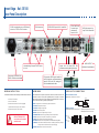
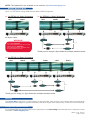
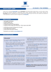
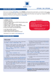
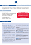
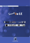
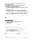
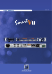
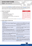
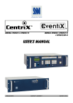
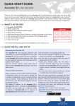
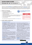
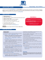
Smart Edge - Ref. STE100
QUICK START GUIDE
Thank you for choosing Analog Way and the Smart Edge. By following these simple steps, you will be able to setup and
use your powerful Hi-Resolution Mixer Switcher with Dual Output Edge Blending within minutes. Discover the Smart
Edge extensive capabilities and intuitive interface while configuring your first show, and unleash your creativity for a new
experience in show and event management by Analog Way.
What’s in the box
1 x Smart Edge (STE100)
1 x AC Power cable
2 x DVI-I male to HD15 female and DVI-D female breakout cable
1 x HD15 to 5 BNC cable
1 x Ethernet cross cable (for device update)
1 x Set of 3 audio 5-pin screw terminals
1 x RCS - Remote Control Software (PC only) *
1 x User Manual (PDF version) *
1 x Quick Start guide (PDF version) *
WARNING !
If required, front handles of the device can be dismantled,
but with caution.
The original screws removed must not be reintroduced to
their location without handles in place.
Substantial damages can occur, including risk of electric shock from the mains voltage.
Only M4x12mm screws can be used.
(They are supplied with the unit)
* Download on our website: www.analogway.com
Optional:
1 x Sync Cable for multiple machine mode (Ref. AW212080)
Quick install and setup
Getting started:
The title layer is only available by an external Remote Control
(RCS/RK-300/TRK-800/ORC50/ARC200).
You may wish to reset the unit to factory settings to get started.
Go to: Menu --> Control --> Default Values --> Yes.
The Layer selection section allows to adjust Layer size,
position, transparency or transitions.
1. Select the Output resolution that matches the native
resolution of your display. You will next be prompted to
choose enable follow mode if desired and output rate.
The Keying/Tilting section allows to access keying and titling
controls and parameters.
enu --> Output --> Output format --> 1024x768 -->
M
Internal Ref --> 60 Hz.
2. The principle of Soft Edge Blending lies in projecting an
image on a wide screen thanks to two or more video
projectors displaying the same content.
We Invite you to read the User Manual if your skills are not
enough to achieve the necessary adjustments.
To see in the User Manual: Page 32 to 34 and page 50 to 54.
3. To display a source, select the [BACKGROUND LIVE]
layer (it will begin to blink) then, select a source (it will
also blink). Press [TAKE] to transition your source from
preview to program output.
There will always be a layer selected (blinking) and a source
selected (blinking) to the selected layer (blinking). To view on
preview or change the contents of a different layer, simply
select it. The Smart Edge has 2 layers available called:
[BACKGROUND LIVE] and [DSK].
Each layer will obscure your view other layer below.
4. To display a titling, select the [PIP] layer, (it will begin to
blink) then select your source (it will also blink). Press
[TAKE] to display the PIP on program out.
The Key layer has similar capabilities than any other layers.
The only constraint is that this layer must necessarily contain a
source of keying that is already applied.
Otherwise the source will be converted to black.
RK-300, TRK-800 and RCS allow to control the Key Layer by
the [PIP2] button.
ORC50 or ARC200 allow to control the Key Layer by [PIP1]
button.
To see the layer beneath, you will need to clear or move the
layer that are the top.
5. To clear the PIP, select the layer (it will blink) then, select
[BLACK]. Press [TAKE] to remove the layer from the
program output.
IMPORTANT:
Simply selecting a menu item will not set it to that value.
Be sure to press the ENTER button when parametering the
menu items.
Smart Edge - Ref. STE100
Front Panel Description
!
Keying and titling are
available with an external
Remote Control
DSK
ADJUST
Select to access keying and titling
controls and parameters
Adjust active layer
EFFECT
STAND-BY
Select a custom transition
Hold for 3 seconds for stand-by Mode
TAKE
Display the selected sources onto the
MAIN output with the selected effects
CONTROL
EXIT/MENU: Home Menu or back one level
ENTER: Validates the menu or command
INPUT SELECTION
#1 to #6: Press to access analog source #1 to #6
DVI 1 to DVI 2: Press to access DVI #1 or DVI #2
SDI 1 to SDI 2: Press to access SDI #1 or SDI #2
BLACK: Clear the active layer
BUTTON COLOR USAGE
Solid red:
#1 = Source is on the main outputs
#2 = Freeze enable
#3 = Stand-by button
#4 = Preset Selection
Solid green: #1 = Source is on Preview
#2 = Function available for modification
Blinking red: Layer/source selected, and is currently active on the main output
Blinking green: Layer/source selected, and is not currently active one the main output
FREEZE
Freeze the input linked to the current layer
on MAIN
PRESET
Recall a custom stored preset (4 memories available).
To store a preset use Menu -> Presets
OUTPUT SETUP
INPUT SETUP
1- Press the EXIT/Menu button from the Home menu
[all functions must be confirmed by the Enter button]
1- Press the EXIT/MENU button from the Home menu [all functions must be
confirmed by the Enter button]
2- Press [Output]
2- Press [Input] and [Autoset ALL]
3- Press [Output format]
4- On Format line, select the display’s native resolution
5- Control or adjust your display device
6- If necessary, select [Test Pattern] in the Output menu
3- If the acquisition has failed, check all connections and perform a manual setup
4- For a comprehensive Input Setup, please refer to user’s Manual
5- For a manual input setup, press the EXIT/MENU button:
a) Press [Input],
b) Select the right input from Input #1 up to SDI #2, then
c) Select [Type].
NOTE: To adjust input Size or Pos, use the [Layer] Menus.
To adjust Blanking, use the Auto-Centering or Blanking adjustments in the
Image menu.
Smart Edge - Ref. STE100
Rear Panel Description
RS-232 communication port on a DB9 female
connector or TCP/IP on RJ45 connector
IP-LAN connectors
Universal Analog Computer/TV/HDTV inputs
#1 to #4
Power supply: IEC/EN/UL/CSA
60950-1, internal, autoswitchable
3.5mm Jack Stereo
Connector input
(unbalanced)
Inputs #1 to #4
SD-SDI/HD-SDI inputs #1 & #2: female BNC
MCO Male connector for
input. DVI #1 & #2 and AUX
AUDIO OUTPUT
Outputs #1 & #2: female HD15, DVI-I
(simultaneous analog and digital outputs)
DVI connectors: DVI-D inputs #1 and #2 on
the DVI-I digital pins, and Universal Analog
inputs #5 & #6 on the DVI-I analog pins.
Use the included break-in cable.
LEFT
Main Audio Output (balanced)
RIGHT
WORKING WITH STE100
HOME MENU
AUDIO INPUTS CONNECTIONS
The features of STE100 can be controled by the external remote control as:
- Orchestra - Ref.: ORC50
The Home Menu is the system’s top level menu, from which all others menus can be
accessed. To access a menu, press the [Menu] button. To navigate in the Home
Menu, please use the knob. To confirm, please use the [Enter] button. You can also
return to the Home Menu by pressing the [Exit] button.
3.5mm Jack Stereo Connector
Inputs #1 to #4: Unbalanced connection
- Axion2 - Ref.: ARC200
- Remote Control Software - Ref.: RCS (supplied)
- Triple Remote Control Keypad - Ref.: TRK-800
- Remote Control Keypad - Ref.: RK-300
!
RK-300, TRK-800 & RCS
can not be used in multiple
machine mode.
- INPUT: configure the 10 individual input types and resolutions
- OUTPUT #1: display the left image
- OUTPUT #2: display the right image
- PRESET: store and use presets
- IMAGE: change source image settings of an input
- KEYING/TITLING: access keying and titling controls and parameters
- LAYER: adjust Layer size, position, transparency or Transitions
- AUDIO: access all audio input and output parameters
- SOFTEDGE: access controls and parameters for Embedded Soft Edge Mode
- CONTROL: access device software information, LAN settings, reset factory settings,
amongst other user oriented functions (see next page)
- VIRTUAL T-Bar: select to access the Virtual T-Bar
Right
Left
Ground
MCO Male Connectors
DVI #1 to DVI #2: Unbalanced connection
Input #7 (AUX): Balanced connection
Main Output: Balanced connection
4
Input #5
LEFT
RIGHT
GROUND(S)
Input #6 LEFT
RIGHT
UNBALANCED
5
L
R
L+
L-
L+
L-
6
GROUND(S)
L
R+
RR
R+
RBALANCED
NOTE: The updater files are available on our web site: http://www.analogway.com
Multiple Machine Mode
Up to 3 x STE100 for Large Wide Screen with 6 Video Projectors.
>> 1 x STE100 = 2 Video Projectors
LEFT
>> 2 x STE100 = 4 Video Projectors
LEFT
RIGHT
RIGHT
LEFT
RIGHT
No Sync Cable.
WARNING !
+ Sync Cable
+ Sync Cable
+ Sync Cable
Sync Cable OPTIONAL.
For multiple machine mode, use one cable
per STE100 (Ref. AW212080).
For a perfect functioning, the follow mode
is recommanded on all units.
Thank you for using 2 x Sync Cable for multiple machine mode.
>> 3 x STE100 = 6 Video Projectors
LEFT
RIGHT
RIGHT
LEFT
LEFT
RIGHT
+ Sync Cable
+ Sync Cable
+ Sync Cable
Thank you for using 3 x Sync Cable for multiple machine mode.
Warranty
This Analog Way product has a 3 year warranty on parts and labor, back to factory. This warranty does not include faults
resulting from user negligence, special modifications, electrical surges, abuse (drop/crush), and/or other unusual damage.
Going further with the STE100
For complete details and operations procedures, please refer to the Smart Edge User’s Manual and our website for further
information: www.analogway.com.
Version : 4.00 - 14/12/11
Code : 140127