1
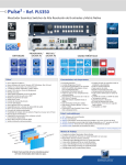
QUICK START GUIDE
Pulse² - Ref. PLS350-3G
Thank you for choosing Analog Way and the Pulse². By following these simple steps, you will be able to set
up and use your powerful Dual Scaler Hi-Resolution Seamless Switcher based on Analog Way’s new Midra™
platform within minutes. Discover the Pulse² capabilities and intuitive interface while configuring your first
show and unleash your creativity for a new experience in show and event management.
WHAT’S IN THE BOX
CAUTION!
• 1 x Pulse² (PLS350-3G)
• 1 x Power supply cord
• 1 x Ethernet cross cable (for device update)
• 1 x Remote Control Software (RCS²)*
• 1 x Set of 6 audio 5-pin screw terminals
• 1 x Front Rack Ears (the parts are stowed in the packaging foam)
• 1 x User Manual (PDF)*
• 1 x Quick Start guide*
* User manual, quick start guide and the RCS² are available on www.analogway.com
If required, front handles of the
device can be dismantled, but
with caution. The original screws
removed must not be reintroduced to their location without
handles in place. Substantial damages can occur, including risk of
electric shock from the mains voltage. Only M4x12mm screws can
be used. (They are supplied with
the unit.)
QUICK INSTALL AND SETUP
Getting started:
You may wish to reset the unit to factory settings to get 4. To display a PIP, select the LAYER B (it will begin to blink)
started. Go to: Menu > Control > Reset/Erase > Default then select your source (it will also blink). Press TAKE to
Values > Yes
display the layer on the Program output.
To see the layer beneath, you will need to clear or move the
1. Select the Output resolution that matches the native
layers that are on top.
resolution of your display. You will next be able to choose
the output rate.
5. To clear the layer or any other layer, select the layer (it
Menu > Output > Output format > 1920x1080 >
will blink) then, select BLACK. Press TAKE to remove the
Internal Ref > 60 Hz
layer from the Program output.
2. Inputs can be configured automatically using the Auto
Set All function. Menu > Intputs > AutoSet All > Yes
It will scan each input and detect the sync type that is
plugged in. You can still do an Autoset or manual setup per
input.
TIP: If you want the Program and Preview to toggle/flipflop
during each Take, enable this feature by going to Menu >
Control > Functions > Preset Toggle.
Once enabled, the old Program output will become the
new Preview after each Take.
The Pulse² has 6 layers available called: FRAME, LAYERS 6. To record and display a Quick Frame follow the steps on
A & B, LOGOS 1 & 2 and a QUICK FRAME. Each layer will page 4.
obscure your view other layers below.
See the next page which describes the button lighting color
code and other front panel features.
3. To display a source, select the LAYER A (it will begin to
blink) then, select a source (it will also blink). Press TAKE Pulse² can be used to display:
to transition your source from Preview to Program output. - sources seamlessly switched in the LAYER A. (Only 1 layer)
- 1 layer and 1 Logo over the LAYER A.
There will always be a layer selected (blinking) and a source
- 2 layer and 1 Logo over a Frame by resizing the LAYER A.
selected (blinking) to the selected layer (blinking). To view
on Preview or change the contents of a different layer, IMPORTANT: Simply selecting a menu item will not set it
simply select it. Only 1 layer can be seen on the Preview to that value. Be sure to press the ENTER button when
at once.
setting the menu items.
Universal Analog
Computer/TV/HDTV:
inputs #1 to #4
Power supply:
100-240 VAC 2.5A 50/60HZ /
FUSE F4A 250 VAC; internal,
autoswitchable; 110W
Control:
Exit/Menu: Home menu
or back one level
Enter: validate the menu
or command
On/Off
Stand-by: Hold
for 3 seconds for
stand-by mode
Menu scroll
knob
DVI connectors:
DVI-D inputs #1 to #4.
Capability to receive digital
audio signal from HDMI
connector via an adaptator
(HDMI-compatible)
3G/HD/SD-SDI:
inputs #1 to #2
HDMI connectors:
HDMI inputs #3 to #6.
Digital audio compliant
Ethernet
Plug
MCO male connector:
for inputs (balanced)
#1 to #4
Shortcut:
Effect: shortcut to transition menu
Preset: recall a custom stored preset
Split Screen: load a split screen preset
Swap: exchange sources between
layer A and layer B
Layer selection:
Frame: non-scaled layer
Logo 1/2: display or change logo
Layer A/B: scaled layers
S/PDIF:
inputs #1 to #2
Input selection:
1 to 4: access source 1 to 4,
display Frame/Logo 1 to 4
HDMI 1/2: access HDMI 1 or HDMI 2,
display Frame/Logo 5 to 6
SDI 1 to SDI 2: access SDI 1 to SDI 2,
display Frame/Logo 7 to 8
Front panel display:
4-line VFD
PULSE² - REF. PLS350-3G / FRONT & REAR PANELS DESCRIPTION
Communication port:
communication port
with a DB9 female
connector
S/PDIF:
outputs #1 to #2
MCO male connector:
for outputs (balanced)
#1 to #2
CAUTION:
The user should avoid disconnecting the power source
(AC input) until the unit is in stand-by mode.
DVI connectors:
DVI-I outputs #1 to #2. Capability to transmit
digital audio signal towards a HDMI connector
via an adaptator (HDMI-compatible)
Universal Analog
Computer TV/HDTV:
outputs #1 to #2
Quick Frame: allows
to quickly display a
foreground Frame
Matrix mode:
#1 to #2: select the output
#1-2, a layer and a source,
then press TAKE
Video output connector:
1 x BNC-F: 3G/HD/SD-SDI
(with audio embedded)
TAKE:
Transition the preselected sources onto the
Program output with the
selected effects
Layer:
Black: clear the layer
Freeze: freeze the input
linked to the current
layer on Program
Layer/source selected or is not currently
active on the Program output
Blinking green:
1- Press the LAYER B button. On the preview screen, the
layer appears as a color rectangle
2- Select an input. On the preview screen, the input
appears in the layer rectangle
3- Adjust the layer with ADJUSTMENT button (Pos & Size
or Zoom)
4- Select a transition (open/close) or an effect into Layer
menu [Home menu]
5- Press TAKE to view the result on the main screen
6- To remove layer, press BLACK then TAKE
7- For another layer setup, repeat from step #1
WORKING WITH PIPS IN MIXER MODE
1- Select the Layer A.
2- Select an input.
3- On the preview screen, the input appears
4- Select an EFFECT (open/close)
5- Press TAKE to view the result on the Program
1- Press the EXIT/MENU button from the Home menu (all
functions must be confirmed by the Enter button)
2- Press Input and Autoset ALL
3- If the acquisition is successful the source appears on Preview.
4- If the acquisition has failed, check all connections and perform
a manual setup
5- For a comprehensive Input Setup, please refer to user’s
Manual
6- For a manual input setup, press the EXIT/MENU button:
a) Press Input,
b) Select the right input from Input #1 up to SDI #2, then
c) Select Active plug,
d) Select Type and choose the input type.
1- Press the EXIT/MENU button from the Home menu (all
functions must be confirmed by the ENTER button)
2- Select Output
3- Select Output format and then Output rate
4- On Format line, select the display’s native resolution
5- Control or adjust your display device (Monitor or Video
Projector)
6- If necessary, select Test Pattern in the Output menu
-M
ode: select to choose which mode the Pulse² will work in (Mixer/Matrix mode)
-O
utput 1: select to set the output types and resolutions of Output #1
-O
utput 2: select to set the output types and resolutions of Output #2
- I nput: select to configure the 8 individual input types and resolutions
- Preset: select to store and use presets
- Image: select to change source image settings of an input
-K
eying/Titling: select to access keying and titling controls and parameters when video
layer is selected
- S creen: setup your background color and your Quick Frame
- L ayer: select to adjust layer size, position, border, transparency or transitions
- L ogos/Frames: select to store (record), use and manage logos and frames into the
Pulse²
- Audio: select to access all audio input and output parameters
-C
ontrol: select to access device software information, LAN settings, reset factory settings, amongst other user oriented functions (see next page)
R+
R-
GROUND(S)
R+
R-
Outputs #1 and #2: balanced & unbalanced connection
Outputs SPDIF #1 and #2: digital audio outputs
Outputs #1 and #2: Embedded audio HDMI (over DVI connectors)
Output SDI: embedded SDI audio output
Inputs # 1 & #2: DVI embedded audio HDMI
Inputs #3 & #4: DVI and HDMI embedded audio HDMI
Inputs SPDIF #1 and #2: digital audio inputs
Inputs HDMI #1 and #2: embedded audio HDMI
Inputs SDI #1 to #2: embedded audio SDI
BALANCED
L+
L-
UNBALANCED
R+
R-
L+
L-
L+
L-
Left
GROUND
GROUND
Right
GROUND
MCO male connectors
Inputs #1 to #4 : balanced & unbalanced connection
AUDIO INPUT/OUTPUT CONNECTIONS
NOTE: To adjust layer Size or Pos, use the Layer Menus. To adjust
Blanking, use the Auto Centering or Blanking adjustments in the
Image menu.
INPUT SETUP
OUTPUT SETUP
FRONT PANEL MENU
Layer/source selected or is currently active
on the Program output
Blinking red:
WORKING IN MIXER MODE
Input can be selected but has no valid signal
#1 = Source is on Preview
#2 = Function available for modification
#3 = Current output on Matrix mode
#1 = Source is on the Program output
#2 = Freeze enable
Solid orange:
Solid green:
Solid red:
BUTTON COLOR USAGE
OPERATION OVERVIEW
HOW TO DO AN AUTOTAKE?
HOME MENU (extract)
CONTROL
FUNCTIONS
AUTOTAKE
ENABLED OR DISABLED
The Autotake function performs a TAKE automatically each time an input is selected.
HOW TO RECORD & DISPLAY A QUICK FRAME?
HOME MENU (extract)
LOGOS/FRAME
RECORD FRAMES
FRAME #1 TO #8
The [Empty] term appears next to all unused slots
QUICK FRAME: full and individual frame that can be displayed on top of every layer.
It is possible to store up to 8 frames in the device non volatile memory.
- Select RECORD FRAMES in the frames menu.
- A white rectangle will appear on your Program display, indicating the frame which will be caught and saved. (The Frame can be
captured in Preview too.)
- To select the Quick frame, please go into the SCREEN menu, select QUICK FRAME menu and then choose a Frame slot. The
selected frame will be your QUICK FRAME.
Now to display it, simply press the front panel button QUICK FRAME. It becomes solid RED.
- To remove the QUICK FRAME, press the QUICK FRAME button on the front panel. It becomes solid green.
TIP: a long press on the BLACK button will clear all layers on Preview. Press TAKE to view your Program display turn to black.
HOW TO DISABLE THE HDCP ENCRYPTION?
HOME MENU (extract)
INPUTS
INPUT #
HDMI OR DVI SETTINGS
HDCP DETECTION
DISABLED
HDCP ENABLE
ENABLED OR DISABLED
HOME MENU (extract)
OUTPUT #1
PREVIEW OUT
AUTOMATIC
The HDCP Encryption can be disabled on HDMI/DVI inputs or/and Program Output #1 / Program Output #2. This can be useful
when you have a computer which is detecting the HDCP compliance of your switcher and protecting the content by encrypting the
signal from this computer. This feature will disable the HDCP compliance on this specific HDMI/DVI input only.
If you want to use HDCP content from your sources, be sure to use only HDCP compliant screens or projector. If it’s not the case,
the output image could be disabled.
Screen will go to black without displaying the HDCP input image, or partially layer out on HDCP content.
The output status can provide you all information about the output in real time. This feature is particularly useful when HDCP is
used with long cable to be sure the communication is well handled.
HOW TO USE THE AUTO-LOCK FUNCTION?
HOME MENU (extract)
CONTROL
FUNCTIONS
AUTO-LOCK
ENABLED OR DISABLED
AUTO-LOCK allows to select an input only if a signal is valid.
WARRANTY AND SERVICE
This Analog Way product has a 3 year warranty on parts and labor, back to factory. This warranty does not include faults resulting
from user negligence, special modifications, electrical surges, abuse (drop/crush), and/or other unusual damage. In the unlikely
event of a malfunction, please contact your local Analog Way office for service.
GOING FURTHER WITH THE PULSE²
For complete details and operations procedures, please refer to the Pulse² User’s Manual and our website for further information:
www.analogway.com
Technical support:
Europe, Middle East & Africa
Tel.: +33 (0)1 81 89 08 76
[email protected]
The Americas
Tel.: +1 212 269 1902
[email protected]
Asia Pacific
Tel.: +65 6292 5800
[email protected]
06/02/2014 - PLS350-3G-QSG
Code: 140161