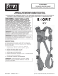
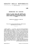
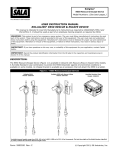
1
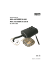
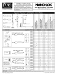
ExoFit NEX™
Full Body Harness
Model Numbers: (See back pages.)
USER INSTRUCTION MANUAL
EXOFIT NEX™ FULL BODY HARNESS
This manual is intended to meet the Manufacturer’s Instructions as required by ANSI Z359 and
CSA 259.10 and should be used as part of an employee training program as required by OSHA
WARNING: This product is part of a personal fall arrest,
restraint, work positioning, climbing, controlled descent,
or rescue system. The user must follow the manufacturer’s
instructions for each component of the system. These
instructions must be provided to the user of this equipment.
The user must read and understand these instructions before
using this equipment. Manufacturer’s instructions must be
followed for proper use and maintenance of this equipment.
Alterations or misuse of this product or failure to follow
instructions may result in serious injury or death.
IMPORTANT: If you have questions on the use, care, or
suitability of this equipment for your application, contact
Capital Safety.
IMPORTANT: Record the product identification information
from the ID label in the inspection and maintenance log in
Section 9 of this manual.
DESCRIPTIONS:
The ExoFit NEX™ Full Body Harness is available in Vest (Figure 1)
and Cross-Over (Figure 2) styles configured with a variety of
features including the following:
•
Tech-Lite™ Aluminum D-Rings - Varied Locations: Front, Back,
Hips, Shoulders
•
Duo-Lok™ Quick Connect Buckles
•
Repel Technology Webbing
•
Hybrid Comfort Padding
•
Revolver™ Vertical Torso Adjusters
•
Tongue Buckle Body Belt
•
Suspension Trauma Straps
NOTE: Some features may not be available on all models of
the ExoFit NEX™ Full Body Harness.
Form: 5903027 Rev: D
© Copyright 2014, Capital Safety.
Figure 1 - ExoFit NEX™ Vest Style Full Body Harness
A
H
B
C
D
E
F
B
I
I
G
A. Shoulder Strap w/Hybrid Padding B. Duo-Lok™ Quick Connect Buckle C. Chest Strap D. Hybrid Chest Pad with i-Safe™ RFID Tag &
Labels E. Revolver™ Torso Adjustor F. Tech-Lite™ Side D-Ring G. Leg Strap H. Tech-Lite™ Dorsal D-Ring I. Trauma Strap
Figure 2 - ExoFit NEX™ Cross-Over Style Full Body Harness
A
G
B
C
D
F
E
A. Shoulder Strap w/Hybrid Padding B. Revolver™ Adjustor C. Hybrid Chest Pad with i-Safe™ RFID Tag & Labels D. Tech-Lite™ Front
D-Ring E. Duo-Lok™ Quick Connect Buckle F. Trauma Strap G. Tech-Lite™ Dorsal D-Ring
2
1.0 APPLICATION
1.1
PURPOSE: The DBI-SALA ExoFit NEX™™ Full Body Harness (Figure 1 and Figure 2) should be used as a component
in personal fall arrest, restraint, work positioning, climbing, controlled descent, or rescue systems (see
Table 1).
ExoFit NEX™ Harnesses included in this manual are full body harnesses and meet ANSI Z359.1, OSHA, and
CSA Z259.10 requirements. See Figure 3 for application illustrations.
WARNING: Working at height has inherent risks. Some risks are noted here but are not limited to:
falling, suspension/prolonged suspension, striking objects, and unconsciousness. In the event of a fall
arrest and/or subsequent rescue (emergency) situation, some personal medical conditions may affect your
safety. Medical conditions identified as risky for this type of activity include, but are not limited to: heart
disease, high blood pressure, vertigo, epilepsy, drug or alcohol dependence, psychiatric illness, impaired
limb function and balance issues. We recommend that your employer/physician determine if you are fit to
handle normal and emergency use of this equipment.
Table 1 - ExoFit NEX™ Full Body Harness Applications
Application
Description
Class A
The full body harness is used as a component of a personal fall arrest system.
Personal fall arrest systems typically include a full body harness and a connecting
subsystem (energy absorbing lanyard). Maximum arresting force must not exceed
1,800 lbs (8 kN). For fall arrest applications connect the fall arrest subsystem
(example: lanyard, SRL, energy absorber, etc.) to the D-ring or attachment element
on your back, between your shoulder blades.
Controlled Descent
Class D
For controlled descent applications, harnesses equipped with a single sternal level
D-ring, one or two frontal mounted D-rings, or a pair of connectors originating
below the waist (such as a seat sling) may be used for connection to a descender or
evacuation system (reference in Z259.10 in Canada).
Rescue
Class E
The full body harness is used as a component of a rescue system. Rescue systems
are configured depending on the type of rescue. For limited access (confined space)
applications, harnesses equipped with D-rings on the shoulders may be used for
entry and egress into confined spaces where worker profile is an issue.
Ladder Climbing
Class L
The full body harness is used as a component of a climbing system to prevent
the user from falling when climbing a ladder or other climbing structure. Climbing
systems typically include a full body harness, vertical cable or rail attached to the
structure, and climbing sleeve. For ladder climbing applications, harnesses equipped
with a frontal D-ring in the sternal location may be used for fall arrest on fixed
ladder climbing systems. These are defined in CSA Z259.2.1 in Canada and ANSI
A14.3 in the United States.
Work Positioning
Class P
The full body harness is used as a component of a work positioning system to
support the user at a work position. Work positioning systems typically include a full
body harness, positioning lanyard, and a back-up personal fall arrest system. For
work positioning applications, connect the work positioning subsystem (example:
lanyard, Y-lanyard, etc.) to the lower (hip level) side or belt mounted work
positioning attachment anchorage elements (D-rings). Never use these connection
points for fall arrest.
Restraint
1.2
CSA Class
Personal Fall Arrest
None
The full body harness is used as a component of a restraint system to prevent the
user from reaching a fall hazard. Restraint systems typically include a full body
harness and a lanyard or restraint line.
STANDARDS: Refer to local, state, and federal (OSHA) requirements governing occupational safety for
additional information regarding Personal Fall Arrest Systems. Refer to the following national standards on fall
protection:
ANSI
Z359.0
Definitions and Nomenclature Used for Fall Protection and Fall Arrest
ANSI
Z359.1
Safety Requirements for Personal Fall Arrest Systems, Subsystems, and Components
ANSI
Z359.2
Minimum Requirements for a Comprehensive Managed Fall Protection Program
ANSI
Z359.3
Safety Requirements for Positioning and Travel Restraint Systems
ANSI
Z359.4
Safety Requirements for Assisted-Rescue and Self-Rescue Systems, Subsystems, and Components
ANSI
A10.32
Fall Protection Systems for Construction and Demolitions
CSA
Z259.10
Full Body Harnesses
ASTM
F887-2011
Standard Specifications for Personal Climbing Equipment
3
Figure 3 - Applications
1
Fall Arrest
2
Restraint
3
Ladder Climbing
4a
Work Positioning
4b
Work Positioning or
Controlled Descent,
with Seat Sling
4c
Work Positioning,
with Seat Sling
4d
Work Positioning,
with Seat Sling Tower Climbing
A
Anchorage
B
Anchorage
Connector
C
Connecting
Subsystem (SRL
shown)
D
Full Body Harness
E
Restraint Lanyard
F
Backup Fall Arrest
System
G
Cable Sleeve
I
Cable
J
Seat Sling
K
H
B
D
I
A
D
2
1
A
A
B
A
B
F
F
3
B
E
A
F
K
E
A
E
E
D
D
D
D
B
Tower Structure
J
J
4a
1.3
G
E
C
Ladder
H
A
B
A
4b
J
4c
4d
TRAINING: This equipment is intended to be used by persons trained in its correct application and use. It is the
responsibility of the user to assure they are familiar with these instructions and are trained in the correct care and use
of this equipment. Users must also be aware of the operating characteristics, application limits, and the consequences of
improper use.
2.0 SYSTEM LIMITATIONS & REQUIREMENTS
Consider the following limitations/requirements prior to installing or using this equipment:
2.1
CAPACITY: ExoFit NEX™ Full Body Harnesses are designed for use by persons with a combined weight
(clothing, tools, etc.) of no more than 420 lbs. (191 kg) per OSHA, 310 lbs. (141 kg) per ANSI Z359.1,
or 352 lbs. (160 kg) per CSA Z259.10-06. Make sure all of the components in your system are rated to a
capacity appropriate to your application.
2.2
FREE FALL: Personal fall arrest systems used with this equipment must be rigged to limit the free fall to 6
feet (1.8 M) per ANSI Z359.1 (see Section 7.1). Restraint systems must be rigged so that no vertical free
fall is possible. Work positioning systems must be rigged so that free fall is limited to 2 feet (.6 m) or less.
Personnel riding systems must be rigged so that no vertical free fall is possible. Climbing systems must
be rigged so that free fall is limited to 18 in. (.46 cm) or less. Rescue systems must be rigged so that no
vertical free fall is possible. See subsystem manufacturer’s instructions for more information.
2.3
FALL CLEARANCE: Figure 4 illustrates fall clearance requirements. There must be sufficient clearance
below the user to allow the system to arrest a fall before the user strikes the ground or other obstruction.
Clearance required is dependent on the following factors:
•
•
•
Elevation of Anchorage
Deceleration Distance
Worker Height
•
•
•
Connecting Subsystem Length
Free Fall Distance
Movement of Harness Attachment Element
4
Figure 4 - Fall Clearance (Lanyards)
Figure 5 - Swing Falls
RD = LL + DD + HH + C
RD
Required Fall Clearance Distance
LL
Length of Lanyard (Specified on labeling)
DD
Deceleration Distance = 4 ft (1.2 m) except:
• for ANSI/OSHA Lanyards with Free Fall
greater than 6 ft (1.8 m) up to 12 ft (3.7
m), or user weights greater than 310 lbs
(141 kg) up to 420 lbs (191 kg); add 1 ft
(0.3 m): DD = 5 ft (1.5 m)
• for CSA E6 Lanyards, add 1.7 ft. (0.5 m):
DD = 5.7 ft (1.7 m)
HH
Height of Suspended Worker
C
Safety Factor = 1.5 ft (0.5 m)
(Factors in D-Ring Slide and Harness Stretch.)
LL
RD
DD
HH
Example: Assuming a 6 ft (1.8 m) tall user with a
typical 6 ft (1.8 m) lanyard with 6 ft (1.8 m) Free Fall,
Fall Clearance calculation would be as follows:
RD = LL + DD + HH + C
RD = 6 ft + 4 ft + 6 ft + 1.5 ft = 17.5 ft
RD = 1.8 m + 1.2 m + 1.8 m + 0.5 m = 5.3 m
C
2.4
SWING FALLS: Swing falls occur when the anchorage point is not directly above the point where a fall
occurs. The force of striking an object in a swing fall may cause serious injury or death. Minimize swing
falls by working as close to the anchorage point as possible. Do not permit a swing fall if injury could occur.
Swing falls will significantly increase the clearance required when a self-retracting lifeline or other variable
length connecting subsystem is used.
2.5
EXTENDED SUSPENSION: A full body harness is not intended for use in extended suspension applications.
If the user is going to be suspended for an extended length of time it is recommended that some form of
seat support be used. DBI-SALA recommends a seat board, suspension work seat, seat sling, or a boatswain
chair. Contact Capital Safety for more information on these items.
2.6
ENVIRONMENTAL HAZARDS: Use of this equipment in areas with environmental hazards may require
additional precautions to prevent injury to the user or damage to the equipment. Hazards may include,
but are not limited to: heat, chemicals, corrosive environments, high voltage power lines, gases, moving
machinery and sharp edges.
2.7
COMPATIBILITY OF COMPONENTS: Unless otherwise noted, DBI-SALA equipment is designed for use with
DBI-SALA approved components and subsystems only. Substitutions or replacements made with non approved
components or subsystems may jeopardize compatibility of equipment and may affect safety and reliability of the
complete system.
2.8
COMPATIBILITY OF CONNECTORS: Connectors are considered to be compatible with connecting
elements when they have been designed to work together in such a way that their sizes and shapes do not
cause their gate mechanisms to inadvertently open regardless of how they become oriented. Connectors
(hooks, carabiners, and D-rings) must be capable of supporting at least 5,000 lbs. (22 kN). Connectors
must be compatible with the anchorage or other system components. Do not use equipment that is not
compatible. Non-compatible connectors may unintentionally disengage (see Figure 6). Connectors must
be compatible in size, shape, and strength. Self-locking snap hooks and carabiners are required by ANSI
Z359.1 and OSHA.
5
2.9
MAKING CONNECTIONS: Use only self-locking snap hooks and carabiners with this equipment. Only use
connectors that are suitable to each application. Ensure all connections are compatible in size, shape and
strength. Do not use equipment that is not compatible. Ensure all connectors are fully closed and locked.
DBI-SALA connectors (snap hooks and carabiners) are designed to be used only as specified in each
product’s user’s instructions. See Figure 7 for illustration of the inappropriate connections stated below. DBISALA snap hooks and carabiners should not be connected:
A. To a D-ring to which another connector is attached.
B. In a manner that would result in a load on the gate.
C. In a false engagement, where features that protrude from the snap hook or carabiner catch on the
anchor and without visual confirmation seems to be fully engaged to the anchor point.
D. To each other.
E.
Directly to webbing or rope lanyard or tie-back (unless the manufacturer’s instructions for both the
lanyard and connector specifically allow such a connection).
F.
To any object which is shaped or dimensioned such that the snap hook or carabiner will not close and
lock, or that roll-out could occur.
G. In a manner that does not allow the connector to align with the fall arrest device (i.e., lanyard) while
under load.
NOTE: Other than 3,600 lb. (16 kN) gated hooks, large throat opening snap hooks should not be
connected to standard size D-rings or similar objects which will result in a load on the gate if the hook or
D-ring twists or rotates. Large throat snap hooks are designed for use on fixed structural elements such as
rebar or cross members that are not shaped in a way that can capture the gate of the hook.
Other Restrictions:
•
Do not make connections where the hook locking mechanism can come into contact with a structural
member or other equipment and potentially release the hook.
•
Do not connect a snap hook into a loop or thimble of a wire rope or attach in any way to a slack wire
rope.
•
The snap hook must be free to align with the applied load as intended (regardless of the size or shape of
the mating connector).
•
A carabiner may be used to connect to a single or pair of soft loops on a body support such as a body
belt or full body harness, provided the carabiner can fully close and lock. This type of connection is not
allowed for snap hooks.
•
A carabiner may be connected to a loop or ring connector that is already occupied by a choker style
connector. This type of connection is not allowed for snap hooks.
Figure 6 - Unintentional Disengagement (Rollout)
Figure 7 - Inappropriate Connections
If the connecting element to which a snap hook (shown) or carabiner
attaches is undersized or irregular in shape, a situation could occur
where the connecting element applies a force to the gate of the snap
hook or carabiner. This force may cause the gate (of either a selflocking or a non-locking snap hook) to open, allowing the snap hook
or carabiner to disengage from the connecting point.
Small ring or other
non-compatibly
shaped element
1.
Force is applied
to the Snap
Hook.
2.
The Gate
presses against
the Connecting
Ring.
3.
The Gate opens
allowing the
Snap Hook to
slip off.
6
2.10 CONNECTING SUBSYSTEMS: Connecting subsystems (self-retracting lifeline, lanyard, rope grab and
lifeline, cable sleeve) must be suitable for your application (see Table 1). See subsystem manufacturer’s
instructions for more information. Some harness models have web loop connection points. Do not use snap
hooks to connect to web loops. Use a self-locking carabiner to connect to a web loop. Ensure the carabiner
cannot cross-gate load (load against the gate rather than along the backbone of the carabiner). Some
lanyards are designed to choke onto a web loop to provide a compatible connection. See Figure 8. Lanyards
may be sewn directly to the web loop forming a permanent connection. Do not make multiple connections
onto one web loop, unless choking two lanyards onto a properly sized web loop.
Figure 8 - Web Loop Connection
1.
Insert Lanyard Web Loop (A) through Web Loop
or D-ring on harness (B).
2.
Insert opposite end of Lanyard through the
Lanyard Web Loop.
3.
1
B
A
Pull the Lanyard through the connecting Web
Loop to secure.
2
3
2.11 ANCHORAGE & ANCHORAGE STRENGTH: Anchorage and anchorage strength requirements are dependent
on the full body harness application (see Figure 3). In accordance with ANSI Z359.1, anchorages selected for Fall
Arrest Systems must meet the anchorage strength requirements defined in Table 2.
Table 2 - Anchorage Strength Requirements
Fall Arrest1
Non-Certified Anchorages:
5,000 lbs (22.2 kN)
Certified Anchorages :
2 times the Maximum Arresting Force for Certified
Anchorages
2
Restraint1
Work Positioning1
Rescue1
Climbing
Non-Certified Anchorages
1,000 (4,5 kN)
Certified Anchorages2:
2 times the foreseeable force for certified anchorages.
Non-Certified Anchorages
3,000 lbs (13.3 kN)
Certified Anchorages2:
2 times the foreseeable force for certified anchorages.
Non-Certified Anchorages
3,000 lbs (13.3 kN)
Certified Anchorages2:
5 times the foreseeable force for certified anchorages.
The structure to which a climbing system is attached must sustain the loads required by that
particular system. See the instructions for the climbing system for requirements.
1 Multiple Systems: When more than one of the defined system is attached to an anchorage, the strength defined for Non-Certified
or Certified anchorages shall be multiplied by the number of systems attached to the anchorage.
2 Certified Anchorage: An anchorage for fall arrest, positioning, restraint, or rescue systems that a qualified person certifies to be
capable of supporting the potential fall forces that could be encountered during a fall or that meet the criteria for a certified anchorage prescribed in this standard.
7
3.0 DONNING AND USE
WARNING: Do not alter or intentionally misuse this equipment. Consult Capital Safety when using this
equipment in combination with components or subsystems other than those described in this manual. Some
subsystem and component combinations may interfere with the operation of this equipment. Use caution when
using this equipment around moving machinery, electrical and chemical hazards, and sharp edges.
3.1
BEFORE EACH USE: Before each use of this equipment inspect the ExoFit NEX™ Full Body Harness
according to Section 5 of this manual.
3.2
PLANNING: Plan your system before use. Consider all factors that will affect your safety during use of this
equipment. Consider the following aspects when planning your system:
3.3
•
ANCHORAGE: Select an anchorage that meets the anchorage requirements specified in Section 2.
•
SHARP EDGES: Avoid working where system components may be in contact with, come in contact with,
or abrade against, unprotected sharp edges.
•
AFTER A FALL: Any equipment which has been subjected to the forces of arresting a fall, or exhibits
damage consistent with the effect of fall arrest forces as described in Section 5, must be removed from
service immediately and destroyed by the user, the rescuer1, or an authorized person2.
•
RESCUE: The employer must have a rescue plan when using this equipment. The employer must have
the ability to perform a rescue quickly and safely.
DONNING AND FITTING THE HARNESS: The ExoFit NEX™ Full Body Harness is available in Vest
(Figure 1) and Cross-Over (Figure 10) styles. Donning procedures will vary with the harness style.
WARNING: Do not alter or intentionally misuse this equipment. Consult Capital Safety when using this
equipment in combination with components or subsystems other than those described in this manual. Some
subsystem and component combinations may interfere with the operation of this equipment. Use caution when
using this equipment around moving machinery, electrical and chemical hazards, and sharp edges.
Figure 9 - Vest Style Harness
Figure 10 - Cross-Over Style Harness
A
A
A. Belt Loops
A. Belt Loops
1 Rescuer: Person or persons other than the rescue subject acting to perform an assisted rescue by operation of a rescue
system.
2 Authorized Person: A person assigned by the employer to perform duties at a location where the person will be exposed to
a fall hazard (otherwise referred to as “user” for the purpose of these instructions).
8
A.
EXOFIT NEX™ VEST STYLE FULL BODY HARNESS: The ExoFit NEX™ Vest Style Harness
incorporates loops for a removable waist belt (see Figure 9). The belt can be installed through the two
loops in the harness located in the lower back shoulder straps. The belt will pass through the harness
just below the padded area. The hip pad, if used, is secured to the belt by passing the belt through the
hip pad loops. Don the Vest Style Full Body Harness per the following steps and corresponding images in
Figure 11:
Step 1.
Locate back D-ring held in position by the D-ring pad; lift up harness and hold by this
D-ring. Ensure the straps are not twisted.
Step 2.
Grasp the shoulder straps and slip the harness onto one arm. The D-ring will be located on
your back side. Ensure that the straps are not tangled and hang freely. Slip your free arm
into the harness and position the shoulder straps on top of your shoulder. Ensure that the
straps are not tangled and hang freely. The chest strap, with quick connect buckle, will be
positioned on the front side when worn properly.
Step 3.
Reach between your legs and grasp the gray leg strap on your left side. Bring the strap up
between your legs and connect it by inserting the tab of the buckle into receptor of quick
connect buckle on the left side as shown in Figure 11. You will hear a click when the tab
engages properly. Connect the right leg strap using the same procedure. To adjust the
leg straps, unlock the webbing lock on the quick connect buckle and pull on the strap.
A plastic end keeper on the end of the strap will stop it from pulling completely out of the
buckle. When the strap is properly adjusted, lock the webbing lock. To release the buckle,
press the silver-colored tabs on the buckle towards each other with one hand, while pulling
on the tab portion of the buckle with the other hand.
NOTE: Locking and unlocking the webbing lock prevents or allows the strap to slide
between the sliding bar and slot on the female end of the quick connect buckle. It does
not control engagement or disengagement of the buckle ends and will not affect the
buckle connection in the event of a fall.
Step 4.
Attach the chest strap by inserting the tab of the buckle into the receptor of the quick
connect buckle. You will hear a click when the tab engages properly. The chest strap should
be 6 in. (15 cm) down from the top of your shoulders. Pass excess strap through the loop
keepers. To adjust the chest strap, unlock the webbing lock on the quick connect buckle
and pull on the strap. A plastic end keeper on the end of the strap will stop it from pulling
completely out of the buckle. When the strap is properly adjusted, lock the webbing lock.
To release the buckle, press the silver-colored tabs on the buckle toward each other with
one hand, while pulling on the tab portion of the buckle with the other hand.
Step 5.
Adjust shoulder straps to a snug fit with the Vertical Torso Adjusters (see Figure 11): Left
and right sides of shoulder straps should be adjusted to the same length and the chest strap
should be centered on your lower chest, 6 in. (15 cm) down from shoulder. The front D-ring
on the vest style harness is moved up or down by adjusting the shoulder straps and leg
straps. Center the back D-ring between your shoulder blades. Note: On applicable models,
the back (dorsal) D-ring can be repositioned up or down as needed for a correct fit. Adjust
leg straps to a snug fit. At least 3 in. (8 cm) of webbing must extend past the buckle on the
leg straps. Adjust the waist belt (if present).
9
Figure 11 - Donning the ExoFit NEX™ Vest Style Full Body Harness
Step 1
Step 2
Step 3
Duo-Lok™ Quick Connect Buckles
Connection: Connect buckle ends by inserting
the tab into the receptor until a click is heard.
Strap Adjustment: Rotate Webbing Lock
to unlocked position . Pull strap to adjust.
Rotate Webbing Lock to locked position .
NOTE: The Webbing Lock does not control
engagement or disengagement of the buckle ends.
Revolver™ Vertical Torso Adjusters
Right
To Tighten: Turn
Ratchet Knob in
direction A.
Left
To Loosen: Pull
Ratchet Knob
out and turn in
direction B.
A
Step 4
B
NOTE: After
adjustment, tug
upwards on the
shoulder straps to
ensure that each
adjustor is locked in
place.
10
A
Step 5
B
B.
EXOFIT NEX™ CROSS-OVER STYLE FULL BODY HARNESS: The ExoFit NEX™ Cross-Over Style
Harness incorporates loops for a removable waist belt. The belt can be installed through the two loops
in the harness located in the lower back shoulder straps (see Figure 10). The belt will pass through the
harness just below the padded area. The hip pad, if used, is secured to the belt by passing the belt
through the hip pad loops. Don the Cross-Over Style Full Body Harness per the following steps and
corresponding images in Figure 12:
Step 1.
Locate the back D-ring held in position by the D-ring pad; lift up the harness and hold by
this D-ring. Ensure the straps are not twisted.
Step 2.
Grasp the shoulder straps between the back and front D-ring and slip the harness over your
head from the left side. Position the shoulder straps on top of your shoulders. Ensure that
the straps are not tangled and hang freely. The D-ring will be positioned on your back when
worn properly.
Step 3.
Grasp the tab of the buckle located at your right hip and insert it into the receptor of the
quick connect buckle (see Figure 12). You will hear a click when the tab engages properly.
Step 4.
Reach between your legs and grasp the gray leg strap on your left side. Bring the strap up
between your legs and insert the tab of the buckle into the receptor of the buckle on the left
side as shown in Figure 12. You will hear a click when the tab engages properly. Connect
the right leg strap using the same procedure. To adjust the leg straps, unlock the webbing
lock on the quick connect buckle and pull on the strap. A plastic end keeper on the end of
the strap will stop it from pulling completely out of the buckle. When the strap is properly
adjusted, lock the webbing lock. To release the buckle, press the silver-colored tabs on the
buckle towards each other with one hand, while pulling on the tab portion of the buckle with
the other hand.
NOTE: Locking and unlocking the webbing lock prevents or allows the strap to slide
between the sliding bar and slot on the female end of the quick connect buckle. It does
not control engagement or disengagement of the buckle ends and will not affect the
buckle connection in the event of a fall.
Step 5.
Adjust shoulder straps to a snug fit with the Vertical Torso Adjusters (see Figure 12):
Left and right sides of the shoulder straps should be adjusted to the same length and the
front D-ring should be centered on your lower chest. The back D-ring should be centered
between your shoulder blades. Note: On ExoFit XP models, the back (dorsal) D-ring can
be repositioned up or down as needed for a correct fit. Adjust the leg straps to a snug fit.
At least 3 in. (8 cm) of webbing must extend past the buckle on the leg straps. Adjust the
waist belt (if present).
3.4
USE OF FALL ARREST D-RING OR ATTACHMENT ELEMENT: For fall arrest applications connect to the
D-ring or attachment element on your back, between your shoulder blades. Side D-rings, if present, are for
positioning or restraint applications only. Front D-ring, if present, is for ladder climbing, positioning, or other
applications with a limited free fall not exceeding 2 feet (0.6 m) with a 900 MAF requirement. For rescue,
back, shoulder, or front D-rings may be used. D-rings on seat sling are for work positioning or personnel
riding.
3.5
MAKING CONNECTIONS: When using a hook to connect to an anchorage or when coupling components
of the system together, ensure roll-out cannot occur. Roll-out occurs when interference between the hook
and mating connector causes the hook gate to unintentionally open and release. Self-locking snap hooks
and carabiners should be used to reduce the possibility of roll-out. Do not use hooks or connectors that
will not completely close over the attachment object. See subsystem manufacturer’s instructions for more
information on making connections.
3.6
CONNECTING SYSTEM COMPONENTS: After properly fitting the full body harness, the user may then
connect to other system components. Follow the guidelines in Section 3.4 when selecting the correct
attachment element.
11
Figure 12 - Donning the ExoFit NEX™ Cross-Over Style Full Body Harness
Step 1
Step 2
Step 3
Duo-Lok™ Quick Connect Buckles
Connection: Connect buckle ends by inserting the
tab into the receptor until a click is heard.
Strap Adjustment: Rotate Webbing Lock to
unlocked position . Pull strap to adjust. Rotate
Webbing Lock to locked position .
NOTE: The Webbing Lock does not control
engagement or disengagement of the buckle ends.
Revolver™ Vertical Torso Adjusters
To Tighten: Turn Ratchet Knob in
direction A.
Left
To Loosen: Pull Ratchet Knob out
and turn in direction B.
Step 4
A
NOTE: After adjustment, tug
upwards on the shoulder straps to
ensure that each adjustor is locked
in place.
Step 5
B
12
3.7
SUSPENSION TRAUMA STRAP: The
ExoFit NEX™ Full Body Harness is equipped with
a Suspension Trauma Strap (Figure 13) to help
prolong allowable suspension time in the event
of a fall from height. It should only be used
in situations where a fall has occurred or for
training. To use the Suspension Trauma Strap:
Step 1.
Unzip the Trauma Strap Pouch on each
hip of the harness and deploy the
Suspension Straps (Figure 13A).
Step 2.
Raise the ends of the straps to access
the hook and loops. Insert the hook
into the loop that provides the desired
strap length.
Step 3.
Lower the Suspension Strap and step
onto the strap to alleviate pressure
of the harness leg straps on the legs
(Figure 13B). Adjust the hook/loop
combination for optimal comfort.
Figure 13 - Suspension Trauma Straps
A
B
WARNING: Maintain an upright position
following suspension. Do not lay down. Seek
medical attention following a suspension.
3.8
EXOFIT NEX GLOBAL WIND ENERGY
HARNESS MODEL REPLACEABLE LUMBAR
PROTECTOR: The Lumbar Protector (A) can be
replaced in the field when worn or damaged. (See
Figure 14)
Figure 14 - Replaceable Lumbar Protector
A
B
Place the ExoFit harness on a flat surface. Pull the
hip belt (B) completely out of the harness to free
the worn/damaged Lumbar Protector (A) and tool
loops (D, if installed).
To install the replacement Lumbar Protector:
Step 1.
Step 2.
Reinsert the hip belt through the left
D-Ring (C), the end of the first tool
loop (D, if installed), belt loops (E) and
(F), and the end of the tool loop (D).
D
D
C
E
Insert the hip belt through the
replacement Lumbar Protector (G), the
second tool loop (H, if installed), the
next two belt loops (I) and (K), the
end of the tool loop (H) and the right
D-Ring.
G
F
I
H
K
H
Completed installation of replacement Lumbar
Protector.
13
4.0 TRAINING
It is the responsibility of the purchaser and the user of this equipment to assure that they understand these
instructions and are trained in the correct care and use of this equipment. They must also be aware of the
operating characteristics, application limits, and the consequences of improper use of this equipment.
IMPORTANT: Training must be conducted without exposing the user to a fall hazard. Training should be
repeated on a periodic basis.
5.0 INSPECTION
5.1
i-Safe™ RFID TAG: The i-Safe™ RFID tag on the ExoFit NEX™ Harness (see “Figure 15 i-Safe™ RFID Tag”)
can be used in conjunction with the i-Safe handheld reading device and the web based portal to simplify
inspection and inventory control and provide records for your fall protection equipment.
Figure 15 i-Safe™ RFID Tag
A
Wrap-Around Cover
B
i-Safe™ RFID Tag
C
Product Labels
A
B
C
5.2
FREQUENCY: Before each use inspect the full body harness according to Section 5.3. The harness must
be inspected by a competent person3, other than the user, at least annually. Record the results of each
formal inspection in the inspection and maintenance log in section Section 9, or use the i-Safe™ inspection
web portal to maintain your inspection records. If you are a first-time user, contact a Customer Service
representative in the US at 800-328-6146 or in Canada at 800-387-7484 or if you have already registered,
go to: www.capitalsafety.com/isafe. Follow instructions provided with your i-Safe handheld reader or on the
web portal to transfer your data to your web log.
IMPORTANT: If the full body harness has been subjected to fall arrest or impact forces it must be
immediately removed from service and destroyed.
IMPORTANT: Extreme working conditions (harsh environments, prolonged use, etc.) may require
increasing the frequency of inspections.
5.3
INSPECTION: Inspect the ExoFit NEX™ Full Body Harness as follows:
Step 1.
Inspect harness hardware (buckles, D-rings, pads, loop keepers, vertical torso
adjusters): These items must not be damaged, broken, distorted, and must be free of sharp
edges, burrs, cracks, worn parts, or corrosion. PVC coated hardware must be free of cuts, rips,
tears, holes, etc. in the coating to ensure non-conductivity. Ensure that release tabs on buckles
work freely and that a click is heard when the buckle engages. Inspect vertical torso adjusters for
proper operation. Ratchet knobs should turn with ease in a clockwise direction and should only
turn counterclockwise when the knob is pulled out.
Step 2.
Inspect webbing: Material must be free of frayed, cut, or broken fibers. Check for tears,
abrasions, mold, burns, or discoloration. Inspect stitching; check for pulled or cut stitches. Broken
stitches may be an indication that the harness has been impact loaded and must be removed
from service. When performing the annual formal inspection, unsnap and open the back pad to
facilitate inspection of the webbing.
Step 3.
Inspect the labels: All labels should be present and fully legible (see Section 8).
Step 4.
Inspect system components and subsystems: Inspect each system component or subsystem
according to manufacturer’s instructions.
3 Competent Person: One who is capable of identifying existing and predictable hazards in the surroundings or working
conditions which are unsanitary, hazardous, or dangerous to employees, and who has authorization to take prompt corrective
measures to eliminate them.
14
Step 5.
Record inspection data: Record the inspection date and results in the Inspection and
Maintenance Log (see Section 9).
Step 6.
Inspect the Stitched Impact Indicator: The stitched impact indicator is a section of webbing
that is lapped back on itself and secured with a specific stitch pattern holding the lap (see
Figure 16). The stitch pattern is designed to release when the harness arrests a fall or has been
subjected to an equivalent force If the impact indicator has been activated the harness must be
removed from service and destroyed.
Step 7.
Inspect Suspension Trauma Straps: Check the trauma strap pouches for damage and secure
connection to the harness. Unzip the trauma strap pouch on each hip of the harness and inspect
suspension trauma straps. Webbing and pouch material must be free of frayed, cut, or broken
fibers. Check for tears, abrasions, mold, burns, discoloration, or knots. Verify that one pouch is
marked ‘Hook’ and the other marked ‘loop’.
IMPORTANT: If inspection reveals a defective condition, remove the unit from service immediately and
destroy it.
NOTE: Only DBI-SALA or parties authorized in writing may make repairs to this equipment.
Figure 16- Stitched Impact Indicator
A. Stitched Impact Indicator
A
A
6.0 MAINTENANCE, SERVICING, AND STORAGE
6.1
WASHING INSTRUCTIONS: Washing procedures for the ExoFit NEX™ Full Body Harness are as follows:
Step 1.
Spot clean the ExoFit NEX™ full body harness with water and a mild soap solution.
IMPORTANT: Use a bleach-free detergent when washing the harness and pads. Fabric softener or dryer
sheets SHOULD NOT be used when laundering and drying the harness and pads.
Step 2.
Water temperature for wash and rinse must not exceed 160° F (70° C).
Step 3.
The harness and pads may be air dried or tumble dried on low heat not exceeding 200° F (90° C).
NOTE: More information on cleaning is available from Capital Safety. If you have questions concerning the
condition of your harness, or have any doubt about putting it into service, contact Capital Safety.
6.2
ADDITIONAL MAINTENANCE AND SERVICING: Additional maintenance and servicing procedures must
be completed by a factory authorized service center. Authorization must be in writing. Do not attempt to
disassemble the unit.
6.3
STORAGE: Store the ExoFit NEX™ Full Body Harness in a cool, dry, clean environment out of direct sunlight.
Avoid areas where chemical vapors may exist. Thoroughly inspect the full body harness after extended
storage.
15
7.0 SPECIFICATIONS
7.1
PERFORMANCE:
•
Maximum Free Fall Distance: No greater than 6 ft (1.8 m), per federal law and ANSI Z359.1.
NOTE: Harness is acceptable for use with free fall distances exceeding 6 feet (1.8 m) if used with
appropriate connecting system.
•
Maximum Arresting Force: 1,800 lbs. (13 kN)
•
Maximum Capacity:
• 420 lbs. (191 kg) per OSHA
• 310 lbs. (141 kg) per ANSI Z359.1
• 352 lbs. (160 kg) per CSA Z259.10-06
•
7.2
7.3
4
Approximate Weight:
Harness only: 3 lbs. (1.4 kg)
Harness with Side D-rings: Add 1/2 lb. (.23 kg)
Harness with Front D-ring: Add 1/4 lb. (.11 kg)
Harness with Back Pad or Belt: Add 1 lb. (.45 kg)
MATERIALS:
•
Webbing Materials: 6,000 lbs (27 kN) Polyester; 7,000 lbs (31 kN) Tensile Strength Nylon; 7,000 lbs
Tensile Strength Nomex4 covered Kevlar4
•
Pad and Label Cover Materials:
• Blend of Nylon and Polyester.
• All outer fabric is Nomex and Kevlar blend fabric. (Arc Flash models only)
• Fire Resistant Hook and Loop Fasteners. (Arc Flash models only)
•
Optional Accessories:
• Hip Pad with side D-rings
• Nomex® covered Kevlar® webbing
• Non-sparking/ Non-conductive PVC coated hardware
• Arc-rated hip, leg, and back pads
• Polyurethane coated, arc-rated dorsal web loop
STANDARDS: When installed and used per the requirements and recommendations in the manual, the
ExoFit NEX™ Full Body Harness meets local, state, and federal requirements defined in Section 1.2.
®: Nomex® and Kevlar® are registered trademarks of DuPont.
16
8.0 LABELING
The following labels must be securely attached and fully legible:
All Models
ANSI Models
CSA Models
17
ANSI Models
CSA Models
Vest Style Harness
Cross-Over Style Harness
18
9.0 INSPECTION AND MAINTENANCE LOG
SERIAL NUMBER:
MODEL NUMBER:
DATE PURCHASED:
INSPECTION DATE
DATE OF FIRST USE:
INSPECTION ITEMS
NOTED
CORRECTIVE ACTION
Approved By:
Approved By:
Approved By:
Approved By:
Approved By:
Approved By:
Approved By:
Approved By:
Approved By:
Approved By:
Approved By:
Approved By:
Approved By:
Approved By:
Approved By:
Approved By:
Approved By:
Approved By:
19
MAINTENANCE
PERFORMED
INSPECTION AND MAINTENANCE LOG
SERIAL NUMBER:
MODEL NUMBER:
DATE PURCHASED:
INSPECTION DATE
DATE OF FIRST USE:
INSPECTION ITEMS
NOTED
CORRECTIVE ACTION
Approved By:
Approved By:
Approved By:
Approved By:
Approved By:
Approved By:
Approved By:
Approved By:
Approved By:
Approved By:
Approved By:
Approved By:
Approved By:
Approved By:
Approved By:
Approved By:
Approved By:
Approved By:
20
MAINTENANCE
PERFORMED
INSPECTION AND MAINTENANCE LOG
SERIAL NUMBER:
MODEL NUMBER:
DATE PURCHASED:
INSPECTION DATE
DATE OF FIRST USE:
INSPECTION ITEMS
NOTED
CORRECTIVE ACTION
Approved By:
Approved By:
Approved By:
Approved By:
Approved By:
Approved By:
Approved By:
Approved By:
Approved By:
Approved By:
Approved By:
Approved By:
Approved By:
Approved By:
Approved By:
Approved By:
Approved By:
Approved By:
21
MAINTENANCE
PERFORMED
ANSI Models
1100381
1100382
1100383
1100384
1100385
1100386
1100387
1100388
1100397
1100398
1100920
1100921
1100922
1100923
1101739
1101742
1101743
1101744
1101749
1101759
1101919
1101921
1101922
1101923
1101924
1102016
1102017
1102018
1102019
1102023
1102705
1102706
1102707
1102708
1102709
1103070
1103071
1103072
1103072H
1103073
1103073H
1103074
1103084
1103085
1103086
1103087
1103088
1103089
1103094
1103095
1113000
1113001
1113001H
1113004
1113004H
1113007
1113007H
1113008
1113008H
1113009
1113009H
1113010
1113010H
1113011
1113011H
1113012
1113012H
1113013
1113013H
1113014
1113014H
1113015
1113016
1113016C
1113018
1113019
1113020
1113021
1113022
1113023
1113024
1113025
1113026
1113027
1113028
1113030
1113031
1113032
1113033
1113034
1113036
1113037
1113038
1113039
1113040
1113043
1113045
1113046
1113046H
1113049
1113049H
1113052
1113052H
1113055
1113055H
1113058
1113058H
1113060
1113061
1113061H
1113064
1113064H
1113067
1113067H
1113068
1113069
1113070
1113070H
1113071
1113072
1113073
1113073H
1113075
1113076
1113076H
1113077
1113078
1113079
1113079H
1113080
1113081
1113082
1113082H
1113083
1113085
1113085H
1113088
1113088H
1113090
1113091
1113092
1113093
1113094
1113095
1113096
1113097
1113098
1113100
1113103
1113105
1113106
1113106H
1113109
1113109H
1113112
1113115
1113118
1113120
1113121
1113124
1113124H
1113127
1113130
1113133
1113135
1113136
1113137
1113138
1113139
1113140
1113142
1113143
1113145
1113148
1113150
1113151
1113151H
1113154
1113154H
1113157
1113157H
1113160
1113160H
1113162
1113163
1113164
1113165
1113166
1113167
1113168
1113169
1113170
1113171
1113172
1113173
1113180
1113181
1113182
1113183
1113184
1113185
1113186
1113187
1113188
1113189
1113190
1113190H
1113191
1113191H
1113192
1113192H
1113193
1113193H
1113194
1113195
1113196
1113197
1113198
1113199
1113200
1113201
1113202
1113203
1113204
1113205
1113206
1113207
1113208
1113220
1113225
1113226
1113227
1113228
1113229
1113230
1113231
1113232
1113233
1113234
1113240
1113241
1113242
1113243
1113244
1113245
1113246
1113247
1113248
1113249
1113250
1113251
1113252
1113253
1113254
1113255
1113256
1113257
1113258
1113259
1113260
1113261
1113262
1113263
1113264
1113269
1113270
1113271
1113272
1113273
1113274
1113275
1113276
1113277
1113278
1113279
1113280
1113281
1113282
1113285
1113286
1113287
1113288
1113290
1113291
1113291H
1113292
1113292H
1113293
1113293H
1113294
1113295
1113296
1113297
1113298
1113303
1113305
1113306
1113307
1113308
1113309
1113310
1113311
1113312
1113313
1113314
1113315
1113316
1113317
1113318
1113319
1113320
1113321
1113322
1113323
1113324
1113325
1113326
1113327
1113328
1113329
1113330
1113331
1113332
1113333
1113334
1113335
1113336
1113337
1113338
1113339
1113345
1113346
1113347
1113348
1113350
1113351
1113352
1113353
1113354
1113355
1113356
1113357
1113358
1113359
1113360
22
1113361
1113362
1113363
1113364
1113365
1113366
1113367
1113368
1113369
1113370
1113371
1113372
1113373
1113374
1113375
1113375H
1113376
1113376H
1113377
1113377H
1113378
1113378H
1113379
1113380
1113381
1113382
1113383
1113384
1113385
1113386
1113387
1113388
1113389
1113390
1113391
1113392
1113393
1113394
1113395
1113396
1113397
1113398
1113399
1113400
1113401
1113402
1113403
1113404
1113405
1113406
1113407
1113408
1113409
1113410
1113411
1113412
1113413
1113414
1113415
1113416
1113417
1113418
1113419
1113420
1113421
1113422
1113423
1113424
1113425
1113426
1113427
1113428
1113434
1113435
1113436
1113437
1113438
1113439
1113445
1113446
1113447
1113448
1113459
1113460
1113461
1113462
1113463
1113464
1113465
1113466
1113467
1113468
1113469
1113470
1113471
1113472
1113473
1113474
1113475
1113476
1113477
1113478
1113479
1113480
1113481
1113482
1113483
1113484
1113485
1113486
1113487
1113490
1113491
1113492
1113493
1113494
1113495
1113496
1113497
1113498
1113499
1113500
1113501
1113502
1113503
1113504
1113505
1113506
1113507
1113508
1113509
1113510
1113511
1113512
1113513
1113514
1113515
1113516
1113517
1113518
1113519
1113520
1113521
1113522
1113523
1113524
1113525
1113526
1113527
1113528
1113529
1113530
1113531
1113532
1113533
1113534
1113535
1113536
1113537
1113538
1113539
1113540
1113541
1113542
1113543
1113544
1113545
1113546
1113547
1113548
1113549
1113550
1113551
1113552
1113553
1113554
1113555
1113556
1113557
1113558
1113559
1113560
1113561
1113562
1113563
1113564
1113565
1113566
1113567
1113568
1113569
1113570
1113571
1113572
1113573
1113574
1113575
1113576
1113577
1113578
1113579
1113580
1113581
1113582
1113583
1113584
1113585
1113586
1113587
1113588
1113589
1113590
1113591
1113592
1113593
1113594
1113595
1113596
1113597
1113598
1113599
1113600
1113601
1113602
1113603
1113604
1113605
1113606
1113607
1113608
1113609
1113610
1113611
1113612
1113613
1113614
1113615
1113616
1113617
1113618
1113619
1113620
1113621
1113622
1113623
1113624
1113625
1113626
1113627
1113628
1113629
1113630
1113631
1113632
1113633
1113634
1113635
1113636
1113637
1113638
1113639
1113640
1113641
1113642
1113643
1113644
1113645
1113646
1113647
1113648
1113649
1113650
1113651
1113652
1113653
1113654
1113655
1113656
1113657
1113658
1113659
1113660
1113661
1113662
1113663
1113664
1113665
1113666
1113667
1113668
1113669
1113670
1113671
1113672
1113673
1113674
1113675
1113676
1113677
1113678
1113679
1113680
1113681
1113682
1113683
1113684
1113685
1113686
1113687
1113688
1113689
1113690
1113691
1113692
1113693
1113694
1113695
1113696
1113697
1113698
1113703
1113704
1113705
1113706
1113707
1113708
1113709
1113710
1113711
1113712
1113713
1113714
1113715
1113716
1113717
1113718
1113719
1113720
CSA Models
1103070C
1103071C
1103072C
1103073C
1103074C
1103085C
1103086C
1103087C
1103088C
1103089C
1113000C
1113001C
1113001CH
1113002C
1113003C
1113004C
1113004CH
1113005C
1113006C
1113007C
1113007CH
1113010C
1113013C
1113015C
1113019C
1113022C
1113025C
1113028C
1113029C
1113030C
1113031C
1113034C
1113037C
1113040C
1113043C
1113045C
1113046C
1113049C
1113052C
1113055C
1113058C
1113060C
1113061C
1113061CH
1113064C
1113064CH
1113067C
1113067CH
1113070C
1113070CH
1113073C
1113075C
1113076C
1113079C
1113082C
1113085C
1113088C
1113090C
1113090CH
1113091C
1113091CH
1113094C
1113094CH
1113097C
1113100C
1113103C
1113105C
1113106C
1113109C
1113112C
1113115C
1113118C
1113120C
1113121C
1113124C
1113125C
1113126C
1113127C
1113128C
1113130C
1113133C
1113135C
1113136C
1113139C
1113142C
1113145C
1113148C
1113150C
1113151C
1113152C
1113153C
1113154C
1113155C
1113156C
1113157C
1113160C
1113163C
1113174
1113175
1113176
1113177
1113178
1113179
1113190C
1113190CH
1113191C
1113191CH
1113192C
1113192CH
1113193C
1113193CH
1113194C
1113195C
1113196C
1113197C
1113199C
1113210
1113211
1113212
1113213
1113214
1113215
1113216
1113217
1113218
1113219
1113220C
1113221C
1113222C
1113223C
1113224C
1113235C
1113236C
1113237C
1113238C
1113239C
1113264
1113265C
1113266C
1113267C
1113268C
1113290C
1113291C
1113292C
1113293C
1113295C
1113296C
1113297C
1113298C
1113299C
1113300C
1113301C
1113302C
1113315C
1113316C
1113317C
1113318C
1113319C
1113320C
1113321C
1113322C
1113323C
1113324C
1113325C
1113326C
1113327C
1113328C
1113329C
1113330C
1113331C
1113332C
1113333C
1113334C
1113335C
1113336C
1113337C
1113338C
1113339C
1113340C
1113341C
1113345C
1113346C
1113347C
1113348C
1113370C
1113371C
1113372C
1113373C
1113385C
1113386C
1113387C
1113388C
1113430C
1113431C
1113432C
1113433C
1113440C
1113441C
1113442C
1113449
1113450
1113451
1113452
1113453
1113454
1113455
1113456
1113457
1113458
1113459C
1113460C
1113467C
1113468C
1113509C
1113510C
1113511C
1113512C
1113513C
1113514C
1113515C
1113516C
1113517C
1113518C
1113519C
1113520C
1113521C
1113522C
1113523C
1113524C
1113525C
1113526C
1113527C
1113528C
1113529C
1113530C
1113531C
1113532C
1113557C
1113558C
1113559C
1113560C
1113561C
1113562C
1113563C
1113564C
1113565C
23
1113566C
1113567C
1113568C
1113569C
1113570C
1113571C
1113572C
1113573C
1113574C
1113575C
1113576C
1113577C
1113578C
1113579C
1113580C
1113581C
1113582C
1113590C
1113591C
1113592C
1113593C
1113594C
1113595C
1113596C
1113597C
1113598C
1113599C
1113600C
1113601C
1113602C
1113603C
1113604C
1113605C
1113606C
1113607C
1113608C
1113609C
1113610C
1113611C
1113612C
1113613C
1113614C
1113615C
1113616C
1113617C
1113644C
1113645C
1113646C
1113647C
1113648C
1113649C
1113650C
1113651C
1113652C
1113653C
1113654C
1113655C
1113656C
1113657C
1113658C
1113659C
1113660C
1113661C
1113662C
1113663C
1113664C
1113665C
1113666C
1113667C
1113668C
1113669C
1113670C
1113671C
1113672C
1113673C
1113674C
1113675C
1113676C
1113677C
1113678C
1113679C
1113680C
1113681C
1113682C
1113683C
1113684C
1113685C
1113686C
1113687C
1113688C
1113689C
1113690C
1113691C
1113692C
1113693C
1113694C
1113695C
1113696C
1113697C
1113698C
1113699C
1113700C
1113701C
1113702C
1121118C
1121119C
1121120C
1121218C
1121219C
1121220C
1122118C
1122119C
1122120C
1122121C
1122122C
1122123C
1122124C
1122218C
1122219C
1122220C
1122221C
1122222C
1122223C
1122224C
1123121C
1123122C
1123123C
1123124C
1123125C
1123126C
1123221C
1123222C
1123223C
1123224C
1123225C
1123226C
1124123C
1124124C
1124125C
1124126C
1124127C
1124223C
1124224C
1124225C
1124226C
1124227C
1125125C
1125126C
1125127C
1125128C
1125225C
1125226C
1125227C
1125228C
1126127C
1126128C
1126129C
1126130C
1126227C
1126228C
1126229C
1126230C
LIMITED LIFETIME WARRANTY
Warranty to End User: D B Industries, Inc., dba CAPITAL SAFETY USA (“CAPITAL SAFETY”) warrants to the
original end user (“End User”) that its products are free from defects in materials and workmanship under
normal use and service. This warranty extends for the lifetime of the product from the date the product is
purchased by the End User, in new and unused condition, from a CAPITAL SAFETY authorized distributor.
CAPITAL SAFETY’S entire liability to End User and End User’s exclusive remedy under this warranty is limited
to the repair or replacement in kind of any defective product within its lifetime (as CAPITAL SAFETY in its sole
discretion determines and deems appropriate). No oral or written information or advice given by CAPITAL
SAFETY, its distributors, directors, officers, agents or employees shall create any different or additional
warranties or in any way increase the scope of this warranty. CAPITAL SAFETY will not accept liability for defects
that are the result of product abuse, misuse, alteration or modification, or for defects that are due to a failure to
install, maintain, or use the product in accordance with the manufacturer’s instructions.
CAPITAL SAFETY’S WARRANTY APPLIES ONLY TO THE END USER. THIS WARRANTY IS THE ONLY WARRANTY
APPLICABLE TO OUR PRODUCTS AND IS IN LIEU OF ALL OTHER WARRANTIES AND LIABILITIES, EXPRESSED
OR IMPLIED. CAPITAL SAFETY EXPRESSLY EXCLUDES AND DISCLAIMS ANY IMPLIED WARRANTIES OF
MERCHANTABILITY OR FITNESS FOR A PARTICULAR PURPOSE, AND SHALL NOT BE LIABLE FOR INCIDENTAL,
PUNITIVE OR CONSEQUENTIAL DAMAGES OF ANY NATURE, INCLUDING WITHOUT LIMITATION, LOST PROFITS,
REVENUES, OR PRODUCTIVITY, OR FOR BODILY INJURY OR DEATH OR LOSS OR DAMAGE TO PROPERTY, UNDER
ANY THEORY OF LIABILITY, INCLUDING WITHOUT LIMITATION, CONTRACT, WARRANTY, STRICT LIABILITY, TORT
(INCLUDING NEGLIGENCE) OR OTHER LEGAL OR EQUITABLE THEORY.
The Ultimate in Fall Protection
CSG USA & Latin America
3833 SALA Way
Red Wing, MN 55066-5005
Toll Free: 800.328.6146
Phone: 651.388.8282
Fax: 651.388.5065
[email protected]
CSG Canada
260 Export Boulevard
Mississauga, ON L5S 1Y9
Phone: 905.795.9333
Toll-Free: 800.387.7484
Fax: 888.387.7484
[email protected]
CSG Northern Europe
5a Merse Road
North Moons, Moat
Reditch, Worcestershire, UK
B98 9HL
Phone: + 44 (0)1527 548 000
Fax: + 44 (0)1527 591 000
[email protected]
CSG EMEA
(Europe, Middle East, Africa)
Le Broc Center
Z.I. 1ère Avenue
5600 M B.P. 15 06511
Carros
Le Broc Cedex
France
Phone: + 33 4 97 10 00 10
Fax: + 33 4 93 08 79 70
[email protected]
CSG Australia & New Zealand
95 Derby Street
Silverwater
Sydney NSW 2128
AUSTRALIA
Phone: +(61) 2 8753 7600
Toll-Free : 1 800 245 002 (AUS)
Toll-Free : 0800 212 505 (NZ)
Fax: +(61) 2 8753 7603
[email protected]
CSG Asia
Singapore:
16S, Enterprise Road
Singapore 627666
Phone: +65 - 65587758
Fax: +65 - 65587058
[email protected]
www.capitalsafety.com
I S O
9001
Shanghai:
Rm 1406, China Venturetech Plaza
819 Nan Jing Xi Rd,
Shanghai 200041, P R China
Phone: +86 21 62539050
Fax: +86 21 62539060