1
Chapter 2: Installation
2-7
I/O Port and Control Panel Connections
The I/O ports are color coded to make setting up your system easier. See Figure
2-2 below for the colors and locations of the various I/O ports.
Figure 2-2. I/O Port Locations and Definitions
2
4
1
3
5
6
7
8
9
Rear I/O Ports
1. Keyboard
6. VGA Port
2. PS/2 Mouse
7. LAN1
3. USB0/1
8. LAN2
4. IPMI LAN
9. UID
5. COM1
Front Control Panel
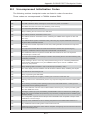
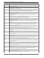
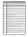
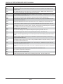
JF1 contains header pins for various front control panel connectors. See Figure 2-3
for the pin definitions of the various connectors. Refer to Section 2-8 for details.
Figure 2-3. JF1: Front Control Panel Header (JF1)
20
19
Ground
NMI
x (key)
x (key)
Power LED
3.3V
HDD LED
Vcc
NIC1 (Link) LED
NIC1 (Activity) LED
NIC2 (Link) LED
NIC2 (Activity) LED
OH/PWR Fail/Fan Fail/UID LED
Vcc
Power Fail LED
3.3V
Ground
Reset
Ground
Power
2
2-11
1