1
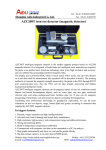
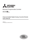
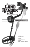
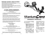
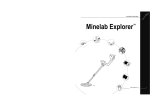
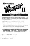
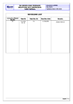
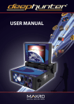
READ CAREFULLY BEFORE OPERATING THE DEVICE!
LEGAL DISCLAIMERS
Comply with the laws and regulations in force within the area while using the device.
Do not use the device in protected or archeological sites and military zones. Notify
any historical and cultural artifacts you find to the concerned authorities.
WARNINGS
RACER is a state-of-the-art electronic device. Do not assemble or operate the device
before reading the user manual.
Do not keep the device and search coil under extremely low and high temperatures
for extended periods. (Storage Temperature: - 20°C to 60°C / - 4°F to 140°F)
Do not immerse the device and its accessories (except for the search coil) in water or
keep them in excessively humid environments.
Protect the device against impacts that may occur during shipping in particular.
RACER may only be disassembled and repaired by authorized service centers.
Disassembling the device for any reason voids the warranty.
Table of Contents
Assembly .................................................................................................................................................................1
General Description of the Device ................................................................................ 2
Battery Details ................................................................................................................................................3
Display......................................................................................................................................................................... 4
Correct Use........................................................................................................................................................... 5
Quick Guide......................................................................................................................................................... 6
Menu........................................................................................................................................................................ 7-9
Modes.............................................................................................................................................................10-11
Ground Balance...............................................................................................................................12-15
Gain and Threshold..............................................................................................................................16
Target ID and ID Filtering.................................................................................................17-18
Pinpoint...................................................................................................................................................................19
Target Distance.......................................................................................................................................... 20
Swinging Speed and Target Identification.................................................... 20
Large or Near-Surface Targets........................................................................................... 20
False Signals and Reasons........................................................................................................ 20
Magnetic Mineralization Indicator............................................................................. 21
Rocks and Searching in Rocky Terrains..................................................... 21-22
Tracking and Effects of Rocks............................................................................................. 22
Metals Under Rocks................................................................................................................. 22-23
Searching in Shallow Water and Beach.............................................................. 23
Messages............................................................................................................................................................. 24
Bluetooth Headphones and Dongle............................................................ 24-25
Technical Specifications.............................................................................................................. 26
Assembly
Page_1
4
2
3
1
1
Insert the washers as shown on the telescopic shaft. Install the telescopic shaft to its location
on the search coil. Secure by tightening the screw and nut.
2
Loosen the twist lock before mounting the telescopic shaft to the upper rod. Press down the pin
and engage the pieces together and tighten the twist lock after the pin is clicked into the hole. Wind
the cable of the search coil on the telescopic shaft without stretching too much. Plug the connector
on the cable to the search coil input socket on the system box and secure by tightening the nut.
3
Loosen the twist lock of the telescopic shaft to extend or shorten it. Adjust the length of the
shaft by keeping the pin located on the rear pressed down and clicking the pin in any of the
holes. Secure by tightening the twist lock.
4
Insert the armrest band through its slot as shown in the figure. Loosen the screws and adjust
the armrest position to your comfort by sliding it down or up and secure by tightening the
screws.
General Description of the Device
Page_2
8
7
1
6
5
2
3
4
10
9
1
Display showing all settings and information
2
Bluetooth headphone module jack (Bluetooth headphone is sold separately)
3
Keypad for navigation among menu options and changing the device settings
4
Ground balance and pinpoint trigger
5
Speaker
6
Battery compartment cover
7
On /Off and volume adjustment button
8
Wired headphone jack
9
Search coil connector socket
10
LED flashlight
Battery Details
Page_3
The device is supplied with 4 pieces of AA Alkaline batteries.
To remove the battery compartment cover, press on the latch and pull out. Insert the batteries
observing correct polarity of + (plus) and - (minus).
The device can be used for approximately 25-30 hours when the batteries are fully charged.
Operating time of other brands and types of batteries available on the market may vary.
AA Alkaline batteries are recommended for the best performance. Good quality Ni-MH
rechargeable batteries can be used, too. Rechargeable batteries with high mAh (capacity)
ratings offer extended operating times than batteries with lower rating. We recommend use of
minimum 2500mAh batteries.
Low Battery Level
Battery icon on the display shows the battery life status. When the charge decreases, the bars
inside the battery icon decrease, too. "Lo" message appears on the display when the batteries
are depleted and the device shuts down after a short period.
Display
Page_4
2
4
5
3
6
1
7
8
9
10
1
Menu providing access to all settings of the device.
2
Target ID and color scale.
3
Cursor indicating the ID of the detected target and its position on the color
scale. It is displayed by itself when the target signal is weak and in a black
box when the signal is strong.
4
Search mode indicator.
5
Section which shows the Target ID during search, the ground balance value
during ground balance adjustment and the estimated target depth during
the pinpoint process. Also, the numeric value of any setting selected from
the menu is displayed in this field.
6
Section which shows the fine tuning value during ground balance
adjustment and current ground balance value during search.
7
Magnetic mineralization indicator.
8
Battery level indicator.
9
Tracking on / off status indicator.
10
Section which shows the warning messages.
Correct Use
Page_5
Incorrect Handling
Correct Handling
Incorrect Use
Correct Use
Incorrect Use
Correct Use
Quick Guide
Page_6
1
Assemble the device as per the instructions on page 1.
2
Insert the batteries by paying attention to +/- polarity.
3
Rotate the on/off switch located behind the device clockwise to turn on the
device. This switch also adjusts the volume.
4
When the device is turned on, it will start in the Two Tone mode. You can
change the mode based on the area that you are searching. For instance, if
your search will be performed on wet beach sand, select the Beach mode.
5
To ground balance, push and hold the trigger forward and pump the search
coil up and down 3cm (1.2'') above the ground until a “beep” sound is heard.
6
You can increase the GAIN if needed. Increasing the gain will offer you
greater depth. However, if the surroundings or the ground cause excessive
noise in the device, you need to lower the gain setting.
7
Testing with various metals is useful for getting familiar with the sounds
produced by the device.
8
Based on the IDs of the metals you don't want to detect, you can set the ID
FILTER and ignore those metals. For instance, if you don’t want to detect
ferrous metals with 20 ID, you can adjust the ID FILTER to 21.
9
You can now start searching.
10
Since your device operates with the motion principle, swing the search coil
right and left maintaining 5cm (2") distance above the ground. If the search
coil does not move, the device will not provide any warning tones even if
the coil is over a metal target.
11
When a target is detected, the ID of the target is displayed on the screen
and the cursor indicates its position in the ID and color scale. The device
also produces a warning tone based on the search mode selected.
12
Upon target detection, you can pinpoint the exact location of the target by
pulling and holding the trigger back.
Menu
Page_7
Select a setting from the menu by using the
up/down buttons. The value of the selected
setting is shown on the display. You can
change the value by using the + and buttons.
If up/down and +/- buttons are kept
pressed for a certain period, options and
values change more rapidly.
If no button is pressed for a while after
selecting a setting or changing its value, the
device automatically returns to MODE option.
Pulling the trigger enables to return to the
MODE option without waiting.
MODE
4 search modes adapted to different ground conditions and target types are offered by RACER.
Names of the search modes are defined as All Metal, Two Tone, Three Tone and Beach on the
menu screen. You can easily switch between the modes by using the direction keys during your
search. See MODES for more details (page 10-11).
GAIN
It is the depth setting of the device. It is also used to eliminate the ambient electromagnetic
signals from the surrounding environment and noise signals transmitted from ground.
Gain setting range is 01-99 and pre-defined for each mode. All modes start at default settings.
They can be manually modified when necessary. Gain adjustment applies to the selected mode;
the modified setting does not affect the gain setting of the other modes.
For more details, please read GAIN AND THRESHOLD on page 16.
THRESHOLD
This setting is used to adjust the humming sound, referred to as the threshold sound, which is
continuously heard in the background in the All Metal mode. It is used to increase the target
signal, in other words, the depth of the device. For more details, please refer to the section titled
GAIN AND THRESHOLD (page 16).
ID FILTER
TARGET ID is the number produced by the metal detector based on the conductivity of the
metals and gives an idea to the user about what the target may be. Target ID is shown with two
digits on the display and ranges between 01-99.
ID FILTER is the ability of the device to ignore unwanted metals. In other words, the detector will
not provide a warning tone or a target ID when such metals are detected. It provides ease of use
by rejecting mineralized rocks (hot rocks) and metals such as iron and foil.
Page_8
Menu
ID Filter cannot be used in the All Metal mode. It is pre-set for the Two Tone, Three Tone and
Beach modes. You can adjust the ID Filter manually according to your personal preferences. See
TARGET ID and ID FILTER section for further information (page 17-18).
TRACKING
When tracking is active (01 position), the device continuously tracks the changing ground
structures and automatically reconfigures the ground balance setting. The invisible changes in
ground affects the detection depth as well as the discrimination ability of the device so it is
possible to operate the device at higher performance using this feature under suitable ground
conditions. Please find further information on TRACKING on page 14.
FREQ.SHIFT
It is the setting which enables to change the operating frequency of the device. It is used to eliminate
the electromagnetic signals that the device receives from another detector which operates in the
same frequency range nearby or from the surroundings. If too much noise is received when the
search coil is lifted in the air, this may be caused by the surrounding electromagnetic signals or too
much gain. In this case, first reduce the GAIN. If the noise is not eliminated, you can choose to shift
the frequency. The device offers 5 different frequencies. Default setting is frequency 03.
IMPORTANT! Frequency shift may impair performance. Therefore, it is suggested that you do
not shift the frequency unless it is required and operate it with the default settings.
AUDIO TONE
It is the setting which allows you to change the target warning tones and the threshold sound in
the background according to your preference. There are 5 sound frequency options available from
a high tone to a low tone. Audio tone setting does not affect the iron tone. Functions in All Metal,
Two Tone and Beach modes; it is inactive in the Three Tone mode. It changes the background
threshold sound in the All Metal mode and gold/non-ferrous tone in Two Tone and Beach modes.
VIBRATION
This feature provides feedback to the user by producing a vibration effect when a target is
detected. It can be used independently or together with the warning tone. When warning tone
is disabled all feedbacks are provided to the user as vibration only during target detection.
Vibration setting is adjusted within the range of 00-05. When it is switched to 0, vibration feature
is completely disabled. If the vibration is at 01 level, the device provides long vibration signals
and at 05 it provides short vibration signals. The magnitude of the vibration effect can vary
according to the depth of the target and the swinging speed. Vibration setting is restored to the
final setting when the device is turned off and on again. This setting is common in all search
modes; change made in any mode also applies to the other modes.
Vibration is not felt in the All Metal mode with weak signals; it will be felt as the signal gets
stronger. In other words, vibration does not start at the depth that warning tones are heard but
at a lower depth. Therefore, if you perform search only with vibration and warning tones of the
device are off, you can miss weaker and deeper signals.
Vibration speed is constant in the pinpoint mode and cannot be adjusted. Vibration is off at 0
position. 01-05 values provide the same level of vibration in the pinpoint mode. When vibration
is used in the pinpoint mode, vibration speed increases as the target is approached and it
reaches the maximum level over the center of the target.
Menu
Page_9
BACKLIGHT
It enables you to adjust the keypad and display backlight level according to your personal
preferences. It ranges between 00-05. Backlight setting is restored to the final setting when the
device is turned off and on again. This setting is common in all modes; change made in any
mode also applies to the other modes.
Keypad and backlight is not lit when it is set to 00 level. When set between 01-05, it is lit when a
target is detected or while navigating the menu and then it goes off.
If you need the keypad and backlight to be lit continuously, after adjusting it to the desired
value, press the down button while keeping the trigger pulled back. Display and backlight will
be continuously on upon performing this action. Repeat the above procedure to cancel the
continuous operation.
LED Flashlight
It is the light used for lighting the scanned area while performing search at night or dark
locations. LED flashlight does not operate when the device is off. It is recommended to turn it on
when necessary since its operation consumes battery charge.
Keeping the trigger pulled back, press the up button once to activate the LED flashlight. Repeat
the same procedure to turn it off.
Page_10
MODES
All Metal
It is the deepest mode of the device. Different than the other modes, this mode features a
threshold tone which is continuously heard in the background.
The device does not discriminate targets while in the All Metal mode and detects all targets
(metal, mineralized rocks etc.). ID of the detected target is shown on the display (except for
negative hot rocks) and the same warning tone is provided for all targets. The warning tone
increases in pitch as the target is approached.
Gain and threshold settings in this mode are set to default values which provide the best
performance on different terrains. You can modify these settings based on ground conditions.
ID FILTER feature is not active in the All Metal mode. Therefore, ID FILTER feature cannot be
selected in the menu.
We recommend using the All Metal mode when discrimination is not important and not using it
in heavy trash areas or areas containing many hot rocks.
Discrimination Modes (Two Tone, Three Tone and Beach)
Different than the All Metal mode, these modes do not have a background sound. The device
only provides a warning tone when a target is detected. A crackling noise can be heard if gain is
not at the right level in these modes. Therefore, the gain adjustment in these modes should be
performed in a location without metals and when the device is silent.
Some of the features of the discrimination modes are similar, however, there are minor
behavioral differences between them. ID FILTER is a frequently used common feature in these
modes. ID FILTER value is preset by the factory for these modes. You can modify these settings if
you want according to the soil conditions where you are searching.
Two Tone Mode
It is the deepest mode among the discrimination modes. It produces good results particularly on
clean sites which do not contain waste metal. More depth can be obtained on sites which are
rocky or contain waste metals by using the ID FILTER feature and swinging the search coil more
slowly (one right/left pass per approximately 1 second). ID FILTER value is set to 10 as a default
value. You can modify this value according to the ID of the target you don’t want to detect.
In the Two Tone mode, the device produces a low tone for iron and for all other metals, it
produces a single tone just like in the All Metal Mode, which increases in pitch as the coil
approaches the target.
It is recommended that you perform tests with mineral rocks and different metals before using
the device in the field in order to get familiar with the warning tones of the device.
Three Tone Mode
In this mode, the device produces a low, grunt tone for iron, a low tone for metals such as gold
and foil, and a high tone for metals in "non-ferrous'' status such as silver, brass and copper. This
mode is ideal to use in fields with different types of metals enabling you to search faster with
audio discrimination. It produces good results for coin hunting in trashy areas.
MODES
Page_11
You can search without detecting unwanted targets in this mode by using the ID FILTER feature
as in the Two Tone mode. ID FILTER value is set to 10 as a default value. It is recommended to
modify this value according to the type of target.
Beach Mode
It is the special mode of RACER developed for conductive grounds (wet sand beach, grounds
with alkali soil etc.). The feature of this mode is its ability to ignore iron and similar targets in this
group and to perform ground balance on any type of ground. While the device performs ground
balance in the range of 40-90 automatically in the other discrimination modes, the device
ground balances in the range of 0-90 in this mode. This enables easier ground balancing on
conductive grounds where normally ground balance cannot be performed at all or performed
with difficulty.
As in the Two Tone mode, the device produces a low tone for iron and for all other metals, it
produces a single tone which increases in pitch as the coil approaches the target.
Different than the other modes, the ID FILTER value is set to 40 as a default value in this mode in
order to ignore ferrous metals or ground noise.
Salt water and alkali grounds are significantly conductive due to high ionization and cause
effects similar to that of iron in detectors. These effects may make it impossible to search for
metals with a standard detector. Existence of iron elimination feature in a detector can improve
the situation but may not be sufficient.
RACER’s Beach mode eliminates such effects and ground noise. Aspects to be taken into
consideration while searching on conductive grounds are explained in more detail in the section
titled Searching in Shallow Water and Beach (page 23).
Page_12
Ground Balance
Ground balance can be performed in three ways in RACER: Automatic, Manual and TRACKING.
If the trigger is pushed forward while performing automatic or manual ground balance, the
device will switch to the All Metal mode automatically on the background without any
indication to the user, regardless of the selected search mode.
Upon completion of ground balance, current ground balance value is shown in the GROUND
PHASE box on the right top corner of the display.
Automatic Ground Balance
Automatic ground balance is performed as follows in all search modes:
1. Find a spot where there is no metal.
2. Push the ground balance trigger forward (GROUND BALANCE value and “Pump the Coil”
warning message is shown on the display) and start pumping the search coil up and down from
about 15-20 cm (~6''- 8'') above the ground down to 3 cm (~1'') off the ground with smooth
movements and keeping it parallel to the ground.
3. Continue until a beep, indicating the completion of ground balance, is heard. Based on
ground conditions, it usually takes about 2-4 pumps for the ground balance to be completed.
4. Upon completion of the ground balance, ground balance value is shown on the display. The
device continues to ground balance and produce a beep sound as long as you keep the trigger
pushed forward and pump the coil. In order to ensure that the ground balance is proper, ground
balance at least 2-3 times and check the ground balance values on the display. In general, the
difference between the values shall not be higher than 1-2 numbers.
5. If you cannot ground balance, in other words, if no beep sound is produced, it means that
either the ground is too conductive or not mineralized or there is a target right below the search
coil. In such a case, retry ground balance at a different spot. Perform manual ground balance if it
still fails.
When the ground balance trigger is released, the device continues to operate in the All Metal
mode for a short period of time and ground balance value stays on the display. This makes it
possible to manually fine tune the automatic ground balance value. Refer to the following
Manual Ground Balance section for further information regarding this feature. If this is not
desired, pull and release the trigger once to return to the main screen.
Ground Balance
Page_13
Manual Ground Balance
Allows you to manually modify the ground balance value. It is not preferred mostly because it
takes time. However, it is the preferred option in cases where a successful ground balance cannot
be performed using other methods or minor corrections are required to the automatic balance.
RACER is designed to allow for automatic ground balancing conveniently on any type of ground.
Therefore, it is recommended to perform automatic ground balance upon start up. However, the
ground may not be suitable for automatic ground balancing in some cases and the device cannot
ground balance on such grounds (Except for the beach mode). For instance, wet beach sand, soils
containing alkali or salty water, lands with high waste metal content, ploughed fields, high
mineralized grounds and grounds with very low mineralization are not suitable for automatic
ground balance. We recommend manual ground balancing for making it easier to search in such
areas. Manual ground balance requires a skill which develops over time through practice.
For performing manual ground balance:
1. Find a spot without metals and switch the device to the All Metal mode.
2. You need to listen the sounds coming from the ground in order to perform manual ground
balance. Pump the search coil up and down from about 15-20 cm (~6''- 8'') above the ground
down to 3 cm (~1'') off the ground with smooth movements and keeping it parallel to the ground.
If the sound gets higher when lifting off the search coil above the ground, the ground balance value
is too low, in other words, the effect from the ground is negative and the ground balance value needs
to be increased by using the ( + ) button. On the other hand, if the sound gets higher when lowering
the search coil to the ground, the ground balance value is too high, in other words, the effect from
the ground is positive and the ground balance value needs to decreased by using the ( - ) button.
3. Push the ground balance trigger forward once and release it. The ground balance value will
be shown on the display and remain there for a moment. You can return to the ground balance
screen by pushing the ground balance trigger forward if the screen switches.
Manual ground balance functions within the range of 0-99.
However, each value covers 5 steps used for fine tuning
within itself and these steps are indicated as multiples of 20
in the Ground Phase indicator shown on the display. For
example, ground balance value shown on the side is 70.80.
Press ( + ) and ( - ) to increase and decrease the ground balance value, respectively. If the key is
pressed once at a time, the values count one by one and if kept pressed down, they change quickly.
4. Repeat the above procedure until the sound heard from the ground is eliminated.
The sound may not be eliminated completely in some areas. In these cases, listen to the sounds
produced when moving the search coil towards and away from the ground to check if the
ground balance is correct. If there is no difference between the two sounds then the ground
balance is set properly.
Page_14
Ground Balance
The device will return to the main screen automatically after a moment upon completion of
ground balance. To return immediately, just pull and release the trigger once.
IMPORTANT! Experienced detectorists adjust the ground balance setting to little positive
response (weak but audible sound is produced when moving the search coil closer to ground).
This method may produce favorable results for experienced users in certain fields where small
targets are searched for.
TRACKING
In this option, the user does not need to make any adjustments. TRACKING feature is activated
from the menu by switching it to 01 position. The word ''Tracking'' is displayed on the right
bottom corner of the screen. The device updates the ground balance automatically as long as
the search coil is swung over the ground and shows the ground balance value in the GROUND
PHASE window on the right top corner. It does not provide any feedback to the user (like ground
balance value or a beep sound in automatic ground balance).
While TRACKING is active, the device can initially produce a loud signal when it detects a
different ground structure (for instance a mineral rock) or a target. In this case, swing the search
coil over the spot where the device produces the signal . If the sound remains the same and the
device shows an ID, it is possibly a target. If the sound attenuates too much or is lost after a few
swings, it means that the device has produced a signal for the different ground structure or a
stone.
It is recommended that you use TRACKING in the All Metal mode and not in the discrimination
modes (Two Tone, Three Tone and Beach) for the best performance.
TRACKING is suitable for use in areas where different soil structures are present within the same
land or in fields where mineral rocks are scattered widely apart. If you use Ground Tracking in
areas where hot rocks are intensely present, the device may not be able to eliminate these high
mineralized rocks or you may miss the smaller or deeper metals.
IMPORTANT! Ensure that TRACKING is off during air tests. Otherwise, the device attempts to
perform ground balance on the target and the depth is reduced.
Ground Balance
Page_15
Ground Balance Value
Ground balance value provides information about the ground you are searching on. Some
typical ground types are as follows:
0-25
Wet salt water or wet alkali soils
25-50
Wet salt water and wet alkali soils covered with dry layers
50-70
Regular, low-quality soils
70-90
Highly magnetic soils, magnetite or maghemite and similar highly mineralized soils,
black sand
Important Details Concerning Ground Balance
1) Upon start up, the ground balance value is set as 90. The device can perform ground balance
automatically within the range of 40-90 in all modes and 0-90 in the Beach mode.
2) If the ground mineralization is too low, automatic ground balance may fail to work in other
modes except for the Beach mode. Try manual ground balance in such a case.
3) You can test the accuracy of the ground balance with the pinpoint mode. After ground
balancing, if you receive no sound or a weak one when you move the search coil closer to the
ground in the pinpoint mode, then the ground balance is successful. If the sound gets louder
when you move the search coil closer to the ground, then the ground balance is not successful.
In this case, simply change your location. If ground balance is not possible despite these efforts,
you should continue your search without performing ground balance.
In order to search without ground balancing, restart the device . If you hear a sound when you
swing the search coil over the ground, switch the device to Three Tone or Two Tone mode (also
adjust the gain) or if you are on a beach, switch to Beach mode. Continue searching after
increasing the ID FILTER value as much as required to eliminate the sound. Since the ID FILTER is
not active in the All Metal mode, you cannot perform a search if you can’t reduce the sound.
4) Once the ground balance is set, it will remain satisfactory for a long time in most areas..
However, if you encounter an excavated, backfilled or geologically composite soil structure, a
ground balance should be performed again to adapt to the varying soil structure.
Page_16
Gain and Threshold
Adjustment of these two settings is critical for a noise-free and high performance operation of
the device. It is possible to obtain an average performance with the default settings. However,
these settings need to be adjusted in order to perform deeper searches as ground and
surrounding conditions allow or to perform search under challenging conditions.
Gain and Threshold in All Metal Mode
In the All Metal mode, search is performed with a continuous humming sound in the
background, also referred to as the threshold sound. The loudness of this hum directly impacts
the detection depth of smaller and deeper targets and it is adjusted by the threshold setting. If
the threshold is set too high, the target signal may not be heard. On the contrary, if it is too low,
you give up the depth advantage this setting offers. In other words, weak signals of smaller or
deeper targets may be missed. Threshold setting comes with the default value at each startup
(not with the last adjusted value). It is recommended for average users to leave this setting at its
default value and for experienced users to adjust to the highest level where they can still hear
the weak target signals.
In the All Metal mode, although the gain setting seems like it is behaving similarly to the
threshold, it actually causes an increase or decrease in the popping sounds and false signals. It is
important to set the sensitivity setting to the highest level possible where no major popping
sounds are heard. For example; if the noise level is suitable for searching and is the same at
sensitivity levels 20 and 50, then 50 should be preferred. Using the factory default levels will be
a good starting point until you get familiar and experienced with the device.
If the device is stable but too noisy, the threshold setting should be decreased. However, if it
sounds erratic and there is too much popping, the gain setting should be lowered.
Gain in Discrimination Modes
Since the threshold setting is not available in the discrimination modes, you can increase the
depth of the device or ensure noise-free operation on different grounds only by using the gain
setting.
In order to adjust the gain in the discrimination modes, first ground balance while the gain is at
its default setting. After ground balance is completed, hold the search coil still or swing over the
ground at search height. Reduce the gain if device receives noise. If not (ensure that the ID
FILTER is also at its default settings when checking this), increase the gain gradually until there is
no popping sound. If the device starts to receive noise during searching, reduce the gain
gradually.
NOTE: The electronic gain of the RACER consists of 3 levels to eliminate the internal
electromagnetic noise and to adjust the saturation level. The electronic gain change points
correspond to levels 39 and 74 on the Gain setting. In case of saturation, you may raise your
search coil a bit or adjust the Gain to the lower electronic gain level. For example, in the All Metal
and Two Tone modes, if the Gain is set to 75 or above and if saturation occurs, adjusting the Gain
to 74 or 39 will minimize or eliminate the saturation. Similarly, if you experience saturation in the
Three Tone mode, adjusting the Gain to 39 will be sufficient. Reducing the gain will not cause a
dramatic decrease in depth.
Target ID and ID Filtering
Page_17
As explained before, target ID is a 2 digit number defining the target, produced by the metal
detector while the search coil goes over a target The number is shown on the display as TARGET ID.
In some cases, the device may produce multiple IDs for the same target. This may result from a
couple of factors. Target orientation, depth, purity of the metal, corrosion, mineralization level of
the soil etc. Direction of the search coil swing may even cause the device to generate multiple
IDs.
In some cases the device may fail to provide any ID. The device needs to receive a strong and a
clear signal from the target in order to provide an ID. Therefore, it may not be able to provide an
ID for targets which are too deep or too small even if the device detects them.
Keep in mind that target IDs are “probable”, in other words, estimated values and it would not be
possible to know the properties of a buried object exactly until it is dug out.
IDs of non-ferrous metals such as copper, silver, aluminum and lead are high. Target ID range of
gold is wide and may fall within the same range of metal wastes such as iron, foil, screw caps, and
pull tabs. Therefore, if you are looking for gold targets, digging out some trash metals is
expectable.
Some possible Target IDs and their ranges are indicated in the table below.
USA Modern Coins
USA 5 cent (nickel)...........................................: 56-58
USA 10 cent (dime) .........................................: 84-86
USA 25 cent (quarter) .................................: 88-92
European Modern Coins
Europe 10/20/50 Euro cent ............: 81-82
Europe 1 Euro .......................................................: 83-85
Europe 2 Euro .......................................................: 74-75
1 TL .......................................................................................: 81-82
Non-ferrous Metals
Gold and gold coins......................................: 54-89
Silver and lead ........................................................: 80-95
Brass and copper................................................: 90-97
Aluminum ....................................................................: 93-97
Waste Metals
Iron, screws, nuts, nails ..........................: 5-25
Foil .........................................................................................: 45-50
Pull-tabs .........................................................................: 55-60
Bottle caps .................................................................: 78-82
Rocks and Mineralized Soils
Magnetized rocks..............................................: 0-5 / 95-99
Iron rocks ........................................................................: 5-25
Salty and alkali soils.......................................: 25-35
Page_18
Target ID and ID Filtering
Brown Area (0-10) : Magnetized rocks
Blue Area (10-40) : Ferrous metals, iron rocks, salty and alkali soils
Yellow/Orange Area (40-70) : Gold, foil, soda can, pull-tabs, some coins etc.
Red Area (70-99) : Copper, brass, aluminum, silver, gold, some coins, pull-tabs, some
magnetized rocks etc.
Above data may vary according to the field conditions. Coins searched throughout the world are
made of different metals and in different sizes in different geographical locations and historical
eras. Therefore, in order to learn the Target IDs of the coins in a specific region, it is suggested to
perform a test with the samples of such coins, if possible.
It may take some time and experience to utilize the Target ID feature in your search area because
Target IDs as well as the depths the IDs are generated by different brands and models of
detectors are also different.
As indicated before, ID FILTER feature is the ability of the device to perform search without
producing warning tones for unwanted metals. ID FILTER feature is not active in the All Metal
mode. ID FILTER values of discrimination modes are preset. Users may modify the ID FILTER
values from the menu anytime.
In order to change the ID FILTER value, select the ID FILTER option from the menu and decrease
or increase the value using the + or - buttons. Please remember that you can miss certain metals,
other than the ones you want to ignore, or signals may become weaker when performing this
action.
For instance, when you set the ID FILTER to 40, the device will ignore all reflected signals with an
ID lower than 40 and will not provide a warning tone. In the case that the ID of a target under a
rock is reflected under 40, the device will not detect the target.
To give another example, in the case of receiving multiple IDs - let's say 35 and 55 - due to target
orientation or metal property, if you filter the IDs up to 40, 35 will fall in the filtered range so the
signal strength may diminish and depth may decrease.
Pinpoint
Page_19
Pinpoint is to find the center or the exact location of a detected target.
RACER is a motion detector, in other words, you are required to move the search coil over the
target or the target over the search coil in order for the device to detect the target. The pinpoint
mode is a non-motion mode. The device continues to give a signal when the search coil is kept
still over the target, too.
Ground balance shall be performed properly in order to ensure precision of pinpointing. It is
recommended to perform ground balance again before performing pinpoint operation on
changing ground structures.
In the pinpoint mode, estimated target distance information is shown on the display. In the
pinpoint mode, the signal tone increases in pitch and volume as the search coil approaches the
target. In this mode, the device does not discriminate or give target IDs. If the device is in the
vibration mode, the speed of vibration will increase as you get closer to the center of target.
To perform pinpoint
1. After a target is detected, move the search coil aside where there is no target response and
pull the trigger back.
2. Keep the trigger pulled and bring the search coil closer to the target slowly and parallel to the
ground.
3. Signal sound becomes stronger and changes in pitch while getting closer to the target center
and also the number indicating target distance on the display decreases.
4. Mark the position which provides the loudest sound using a tool or your foot.
5. Repeat the above procedure by changing your direction 90°. Actions to be performed from a
couple of different directions will narrow the target area and provide you with the most exact
details of the target position.
Page_20
Target Distance
The device provides an estimated target distance according to the signal strength. In the
pinpoint mode, estimated target distance is shown on the display in cms (or inches - please see
below for details) while getting closer to the target.
Distance detection is adjusted presuming that the target is a 2.5cm (1'') coin. Actual distance
varies according to the size of the target. For instance, it will indicate more distance for a target
smaller than a 2.5cm (1'') coin and less distance for a larger target. Pinpoint procedure is not
intended for depth determination but location determination. Therefore, it is recommended
that the distance indicator on the display is used for determining the proximity to the target.
IMPORTANT! If you want the target distance to be displayed in inches instead of cms please do
the following: While the device is off, press and hold the plus (+) and minus (-) buttons
simultaneously and turn the device on. ''US'' will be displayed. To switch back to cms, you need
to turn the device off and then repeat the above procedure. While the device is initializing, ''IS''
will be displayed.
Swinging Speed and Target Identification
RACER is a detector with very high detecting speed. When you detect a target with RACER, you
should make wider passes instead of narrowing the sweeps and making quick sweeps over the
target like in other metal detectors, in order to receive an accurate ID from the target. If your
swinging speed is not correct, the device may not detect the target accurately and the target ID
numbers may bounce. Also, do not tilt the coil up or down while swinging and keep it parallel
to the ground.
Large or Near-Surface Targets
Targets which are near the surface may give multiple different signals to the device. If you
suspect a target near the surface, lift the search coil and swing it more slowly until a single signal
is received. Also, if there is a large target near the surface it may cause an overload in the search
coil and the device starts to generate a continuous sound which resembles a siren. “Saturation”
message is shown on the display simultaneously. In such a case, lift the search coil up until the
message disappears.
False Signals and Reasons
Sometimes, the device may produce signals which are similar to a target signal although no
metal target is present. There are various reasons for the false signals received by the device. The
most known ones are ground mineralization or rocks with high mineral content, surrounding
electromagnetic signals, operation of another nearby detector, rusted or corroded iron or foil in
the soil, gain or threshold values set too high.
Surrounding electromagnetic signals can be eliminated by reducing the gain. If another
detector is operating nearby, you may attempt to change the frequency or perform your search
at a distance where no interference occurs. For ground mineralization or rocks with high mineral
content, and gain and threshold set too high, please read the related sections (Ground Balance,
Rocks and Searching in Rocky Terrains, Metals Under Rocks, Gain and Threshold).
Sayfa_21
Page_21
Magnetic Mineralization Indicator
The Magnetic Mineralization Indicator consists of 8 levels.
The indicator is shown empty at low mineral levels during
search and at start up. In areas where the magnetic mineral
level is high, the indicator level increases according to the
intensity. This measurement can be summarized as the level
of magnetic property and intensity of the ground. Simply, if
you are working in an area which contains intense and
magnetized minerals, the level will be high. If you are
working on a less intense ground, the level will be low.
This measurement is important from two aspects. First, on grounds with high magnetic
mineralization, search depth is low and users should be aware of this fact. Second, magnetic
mineralization is a property which is particularly seen with mineralized rocks and this
measurement plays an important role for the device to eliminate the false signals produced by
these rocks.
Rocks and Searching in Rocky Terrains
Challenging ground conditions arise especially when conductivity and magnetic properties of
the ground is too intense. Operation of the device over such ground is made possible by
selecting the best operating mode and using proper ground balance, gain and threshold
settings.
Stones and rocks or cavities inside the ground are as important as the ground itself in regards to
the search and target detection quality.
Soil and rocks have two different properties just like the targets you are searching for. One of
them is the intensity and the other one is the conductivity - magnetic permeability ratio and
these two properties are independent from each other. In this manual, the conductivity magnetic permeability ratio will be referred to as ID in short. High magnetic permeability, low
conductivity results in low ID. Soil or rocks can be highly permeable and have low or high IDs as
well. If the conductivity increases relatively to magnetic permeability then the ID will also
increase.
Hot rocks are classified as negative or positive based on their ID being low or high in comparison
to the ID of the soil they are in. One or both of the types may be present in a field. The negative
and positive effects mentioned here will only be valid if ground balancing is properly done on
the existing ground. Otherwise, soil itself will not act differently from hot rocks in terms of ID. In
''TRACKING'' however, conditions will differ. Therefore, the effects of rocks in ''TRACKING'' will be
discussed separately. Here we are referring to a proper ground balance without ''TRACKING''.
Positive rocks act just like metal and produce a metal sound. In the All Metal mode they produce
a “zip zip” sound when the search coil is moved over them. If the signal is strong enough, the
device may produce an ID for these rocks. Negative rocks in the All Metal mode, produce a long
“boing” sound when the search coil is moved over them. The device does not give an ID for
these rocks even if the signal is strong.
Page_22
Positive rocks provide a typical metal sound in discrimination modes. Negative rocks do not
provide a sound in discrimination modes (except for rare cases of false signals).
Therefore, you can make a decision by listening to the warning tones produced by the device in
the field. If you receive a metal sound, it means that you either detected a positive rock or a piece
of metal. If you receive a strong signal and a stable ID, you can distinguish if the detected target
is a rock or metal by checking the ID. However, remember that weak signals may produce
different IDs and metals under rocks may produce different metal signals. Therefore, the most
appropriate action is to dig up when a metal signal is received.
If you are operating with discrimination modes and you know the ID of the surrounding rocks,
you can use the ID filtering to eliminate the rocks. However, this may not be sufficient to avoid
all rock signals. The device may still receive signals from rocks because soil and rocks together
will form a combined effect and generate a different ID than those of rocks.
Tracking and Effects of Rocks
When the tracking is active, the device may give a warning tone and ID when it passes over a hot
rock because the effect of the rock will be different than the ground's. If you swing the search
coil over the rock, tracking will automatically adjust the setting and the warning tone/ID will
either disappear or diminish significantly. Because there is a slight delay in tracking, you may
hear a strong signal at the first one or two swings until the setting is adjusted. Then the sound
will get weaker and disappear. This will not happen with metal targets because metals will
prevent the device from ground balancing. Therefore, in tracking, if you are getting a constant
signal over a target after repeated swings, there is a high possibility that the target is a metal.
Moving from over a rock back to soil, the device may give signals to the ground for a few swings
until the ground balance setting is updated again. This is normal and should not mislead you.
Tracking is not recommended to eliminate rocks under normal conditions. It is recommended
for use in areas with changing soil types.
Metals Under Rocks
RACER increases the possibility of detecting metal targets under mineralized rocks through the
proper adjustment of your settings. The combined effect created by the rock and metal together
is lower than the effect that the metal creates by itself and the displayed ID will be different than
the metal's expected ID. The displayed ID is formed by the combination of rock and metal
together and gets closer to the ID of the rock if the size of the metal is smaller in relation to the
rock. Keep in mind that metals under hot rocks will never appear with their own metal ID. For
instance, a gold piece under a brick may produce an iron tone and ID.
Remember this very simple principle as it will save you lots of time: “If the target you detect is not
a stone, it can be metal”.
The key to detecting targets under mineralized rocks, particularly when positive rocks are in
question, is the knowledge of the maximum ID value produced by the surrounding positive
rocks. If you are performing a search in the All Metal mode, monitor the ID produced by the
device. If the ID provided by your device is close to the rock and iron zone, it is quite possible that
you detected a target under the rock. Since ID FILTER cannot be used in the All Metal mode, you
need to discriminate by taking the value on the display into consideration.
Page_23
If you filter off the rocks with a correctly adjusted ID FILTER setting in discrimination modes, you
can hear the signal of the target under the rock if the target signal has a slightly greater effect
than the filtered ID. The important thing here is that if you detect a target and dig out a rock, you
should note the ID you got before digging and use it as the ID Filter value the next time.
For instance; the hot rocks in your search field tend to give IDs around 3-4. In this case, you
should set the ID Filter to maximum 5. This way you can eliminate rocks and receive the signals
of metals underneath. If you set the ID Filter too high unnecessarily, you will lose metals along
with rocks.
If the hot rocks in your search area tend to give high IDs, then the chances of missing the signals
of small metals underneath will be high as well.
Searching in Shallow Water and Beach
All search coils of the RACER metal detector are waterproof. This provides convenient searching
in shallow water and on the beach. When searching around water, be careful not to get the
system box wet.
As explained before, salt water and alkali grounds are significantly conductive and cause effects
similar to iron in detectors. RACER’s Beach mode is specially designed for such conditions. You
can perform your search easily using the Beach mode without requiring any special settings.
Beach mode is ideal for wet beach sand. You can use the other modes while performing search
over dry beach sand.
You should consider the following while performing search over wet beach sand or water:
1) When you swing the search coil over the holes you dig in wet beach sand, you can receive
metal signals, this is a normal condition.
2) The search coil may give false signals when going into and coming out of the water so please
try to keep the coil either in or out of the water.
Messages
Page_24
Warning messages are shown on the bottom of the display during search. Messages that may
appear are as follows:
Saturation
It appears on the display simultaneously with the saturation alarm sounding like a siren. This
happens when the search coil encounters a near surface or a very large object. The device
reverts back to normal operation if you lift the coil up. If the alarm and the message continues
along a long line, you may be over a long metal such as a pipe.
Pump the coil
It appears when the trigger is pushed forward for ground balancing. Does not indicate any error
or problem. It only indicates what should be done.
Check Coil
It indicates an interruption in the search coil transmitter signal. The search coil connector may be
unattached, loose or disconnected. If you own another detector with the same coil connector,
please be sure that you have not attached the wrong coil by mistake. If none of the above exists,
the search coil or its cable may have a defect. If the issue continues when you change the search
coil, there may be an issue in the coil control circuit.
Bluetooth Headphones and Dongle
Instructions
These instructions explain the usage of the Philips SHB700 Bluetooth headphones with the
Bluetooth dongle used in the RACER metal detector. For more details on using the headphones
with other devices, charging and other features, please refer to the headphone’s original manual
included in the box.
Charging the BT Headphones (USB)
• Press and hold the play/pause
button for more than 1 second.
• If 1 short beep is heard and the LED starts flashing blue, it means that the charge is over 50%.
If LED starts flashing white, it means that the charge is below 50%.
• To charge the headphones, plug the headphones into a powered USB port using the USB
charging cable. LED turns white during charging and turns off when the headphones are fully
charged.
Pairing the Headphones with the Dongle
1. Make sure that the Bluetooth headphones and the device are turned off.
2. To initiate the pairing mode on the headphones, press and hold the play/pause
at least 4 seconds.
button for
3. The LED will start flashing blue. Keep on pressing the button. When the LED starts flashing
white and blue alternately, it means that the headphones are in pairing mode.
Page_25
4. The headphones will stay in the pairing mode for about 2 minutes. If it does not pair with the
dongle during this time, it will shut off automatically.
5. Make sure that the device is still off and insert the Bluetooth dongle in its slot
on the side of the system box as shown in the figure. If you insert the Bluetooth
module while the device is on, you need to turn the device off and on again.
6. Push forward and hold the RACER's ground balance/pinpoint trigger and press the down
button once. The letters ‘’bt’’ will appear on the screen and scanning for pairing will start.
Scanning will be indicated in the lower right corner in the magnetic mineralization
window. Scanning will last around 1 minute. To cancel, push the trigger back once and
release.
7. When the pairing is completed ‘’bt’’ will disappear on the RACER screen, the LED will stop
flashing white and the LED will start flashing blue every 6 seconds.
8. Upon pairing, the sounds of the device will automatically be heard through the BT
headphones.
Cancellation of Pairing and Turning off the BT Headphones
To stop using the BT headphones, press and hold the play/pause button. The LED will flash white
and the headphones will turn off. The letters ‘’bt’’ will appear and the sounds will be heard from
through the device.
If you remove the module while the Bluetooth is active, the sound will not be transmitted
through the device. In such a case, you need to turn the device off and on again.
NOTE:
• Once the BT headphones are paired with the dongle, you do not have to go through the pairing
process again, as long as the dongle stays inserted in the device. All you need to do is to turn the
headphones on. The headphones and the dongle will be paired within 10 seconds.
• If there are many Bluetooth devices around you, the pairing may fail and you may need to try a
few times.
Technical Specifications
Operating Principle
:
Operating Frequency :
VLF Induction Balance
14 kHz (+/- 100 Hz bandwidth)
Audio Frequencies
:
5
Search Modes
:
4 (All Metal/Two Tone/Three Tone/Beach)
Ground Balance
:
Automatic / Manual / Tracking
Pinpoint
:
Available
Frequency Shift
:
Available
Vibration
:
Available
Gain Setting
:
01-99
Target ID
:
01-99
Search Coil
:
29cm x 18.5cm (11" x 7") DD
Display
:
Custom LCD
Weight
:
1.4 kg (3 lbs.) including search coil and batteries
Length
:
120cm - 140cm (47" - 55 ") adjustable
Battery
:
4 x AA Alkaline
Warranty
:
2 years
Makro Detectors reserves the right to change the design, specifications
or accessories without notice and without any obligation or liability
whatsoever.
Page_26