1
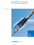
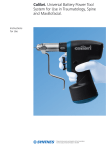
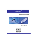
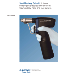
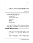
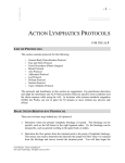
Electric Pen Drive. Compact system
for a wide range of applications.
User’s Manual
Synthes
Electric Pen
Drive System
Table of Contents
Introduction
Operating Instructions
Product Information
Indications
2
Specifications
3
Drive Unit
15
Hand Switch
17
Consoles
23
Foot Switch
32
Drilling Speed Attachments
38
Screw Insertion Attachments
41
K-Wire Attachment
42
Sawing Attachments
43
Burring Speed Attachments
48
Light Adaptor for Small Battery Drive
52
Sterilization
54
Troubleshooting
56
Set Lists
58
Cutting Tools
66
Synthes
Indications
The Electric Pen Drive is indicated for
screw insertion, pin and wire placement,
cutting of bone and metal, drilling,
decorticating, shaping and smoothing
of bones and teeth in a wide variety of
surgical procedures, including but not
limited to general orthopaedic trauma,
foot, hand, maxillofacial, neurosurgical,
oral, otolaryngological, reconstructive,
and spine surgery.
Drilling
K-wire insertion
2
Synthes Electric Pen Drive User’s Manual
Specifications — System
The device complies with the following standards:
IEC 60601-1/60601-1/60601-1-2/60601-1-4
IEC 61000-6-1/61000-6-2/61000-6-3/6000-6-4
Medical Electrical Equipment
UL 60601-1
With regard to electrical shock, fire, mechanical hazards,
only in accordance with UL 60601-1 and CAN/CSA C22.2
No. 601.1
Environmental conditions
Operation
Transportation
and storage
Temperature
10° – 40°C
50° – 104°F
–20° – 50°C
–4° – 122°F
Relative humidity
30%– 75%
10%– 75%
Atmospheric
pressure
500 – 1,060 hPA
0.5–1.06 bar
500 – 1,060 hPA
0.5–1.06 bar
Duty cycle
Intermittent operation
Xsec on
Ysec off
Cycles
Drill / Burr Attachments
30
30
unlimited
Reciprocating
Saw Attachment
30
60
5 cycles
Oscillating
Saw Attachment
25
60
5 cycles
Sagittal Saw Attachment
30
60
5 cycles
These recommendations for times of use for the attachments
for Electric Pen Drive have been determined under average
load with an ambient air temperature of 25°C (77°F).
Generally, electrical systems can heat up if in constant use.
For this reason, the duty cycle times listed above should be
followed to allow the Drive Unit and attachment to cool
down after constant use. If this is observed, the system will
avoid overheating and possibly harming the patient or user.
After the above indicated number of cycles, the respective
attachments must be allowed to cool down for 30 minutes.
The user is responsible for following the duty cycles indicated.
If longer periods of constant use are required, an additional
Drive Unit and / or attachment should be used.
Caution
– Carefully observe the above recommended duty cycles.
– Always use new cutting tools to prevent heating of the
system due to reduced cutting performance.
– For oral surgery, it is recommended to prevent any contact
of warm components with soft tissues as temperatures
even around 45°C may damage the lips and oral mucosa.
– Careful maintenance of the system will reduce heat
development in the Drive Unit and the attachments.
The use of the Synthes Maintenance Station (05.001.099)
is strongly recommended.
– The Electric Pen Drive should not be stored or operated in
an explosive atmosphere.
Synthes
3
Specifications — Standard Console with Irrigation (05.001.000)
Specifications
– Weight: 5.4 kg (12 lbs)
– Dimensions: 250 mm x 155 mm x 175 mm
(9.8 in x 6.1 in x 6.9 in)
– Operating voltage: 100 VAC–240 VAC, 50/60 Hz
– Degree of protection: IP X0
Slide control
For adjusting maximum speed for
Drive Unit 2
Selection switch
For torque limiting
Slide control
For adjusting
maximum speed
for Drive Unit 1
Selection switch
For irrigation
ON/OFF LED
Connector
For Light Adaptor
for Small Battery
Drive
Flow rate
adjustment knob
For irrigation
Connector
For Foot
Switch
Connector
For Drive
Unit 1
Irrigation
pump
Connector
For Drive
Unit 2
Additional instrument
05.001.001* Standard Console without irrigation
The standard console is also available without the pump
module.
4
Synthes Electric Pen Drive User’s Manual
* Also available
Specifications — Basic Console (05.001.002)
The Basic Console includes connectors for one Drive Unit,
a Foot Switch and the Light Adaptor for Small Battery Drive.
It includes speed control for the Drive Unit but does not offer
torque limiting or irrigation options.
Connector
For Drive Unit
ON/OFF LED
Connector
For Foot Switch
Connector
For Light Adaptor
for Small Battery
Drive
Synthes
5
Specifications — Electric Pen Drive, 60,000 rpm (05.001.010)
Specifications
– Weight: 183 g (6.45 oz)
– Length: 130 mm (5.1 in)
– Clockwise and counterclockwise rotation
– Continuously variable speed: 0 to 60,000 rpm
– Degree of protection: IP 54
– Removable variable-speed Hand Switch controls
rotational speed
– Attachment release ring facilitates one-handed
insertion/removal of attachments
– Mode switch turns Drive Unit to off / lock ( ) for safety
during Drive Unit and / or attachment exchange, selects
clockwise (
) or counterclockwise (
) rotation,
and allows cable insertion/removal ( ).
– Locking mechanism prevents inadvertent changes to
mode switch
Important:
– Do not lay the Drive Unit on magnetic sterile covers or in
the immediate vicinity of other magnetic objects. This could
activate the Drive Unit.
– When two 60,000 rpm Drive Units are connected and the
speed is controlled with the Foot Switch, one Drive Unit
must be switched to LOCK ( ). Otherwise, neither of the
Drive Units will function for safety reasons.
– In all other cases, the first speed control device to be activated functions. As long as this device is activated, all others
are deactivated (including the Small Battery Drive).
– When a 90,000 rpm Electric Pen Drive and a 60,000 rpm
Electric Pen Drive are connected simultaneously, the
90,000 rpm Electric Pen Drive only works if the 60,000 rpm
Electric Pen Drive is set to the LOCK ( ) position on the
mode switch. Otherwise the 60,000 rpm Electric Pen
Drive works.
6
Synthes Electric Pen Drive User’s Manual
Cable insertion
Locking mechanism for
mode switch
Forward (clockwise)
Reverse (counterclockwise)
Lock (Drive Unit off)
Cable insertion/removal
Specifications — Electric Pen Drive, 90,000 rpm (05.001.011)
Specifications
– Weight: 124 g (4.4 oz)
– Length: 102 mm (4 in)
– Clockwise and counterclockwise rotation
– Continuously variable speed: 0 to 90,000 rpm
– Degree of protection: IP 54
The 90,000 rpm Electric Pen Drive can only be operated with
a Foot Switch. The FWD/REV changeover must to be done with
the 2-pedal Foot Switch (05.001.017).
The cable is permanently fixed to the pen.
To use the 90,000 rpm Electric Pen Drive, you need a console
with the latest software. Those consoles are identifiable with
the following features:
Serial number:
– Higher than 00773 for the Standard Console with irrigation
(05.001.000)
– Higher than 01152 for the Standard Console without
irrigation (05.001.001)
– Higher than 0336 for the Basic Console (05.001.002)
– If a console has a lower serial number than mentioned
above, but has a round, green sticker on the bottom
plate label of the console, the console has already been
upgraded to the latest software version.
Consoles with a lower serial number and without a sticker
on the bottom plate, must be sent to Synthes customer
service for a software update, for use with the 90,000 rpm
Electric Pen Drive.
Important:
– Only the Burr Attachments are compatible with this Drive Unit.
– The Hand Switch cannot be used.
– It is not possible to use two 90,000 rpm Electric Pen Drives.
If two of them are plugged in, neither of them will work
for safety reasons.
– When a 90,000 rpm Electric Pen Drive and a 60,000 rpm
Electric Pen Drive are connected simultaneously, the
90,000 rpm Electric Pen Drive only works if the 60,000 rpm
Electric Pen Drive is set to the LOCK ( ) position on the
mode switch. Otherwise the 60,000 rpm Electric Pen
Drive works.
Synthes
7
Specifications — Hand Switch (05.001.012) and Foot Switches (05.001.016,
05.001.017)
Hand Switch
– May be removed without disconnecting the cable
from the Drive Unit
– Allows variable speed control of the Drive Unit
– Includes a safety switch and pull-out finger rest
Pull-out
finger rest
Safety switch
Positioning arrow
8
Synthes Electric Pen Drive User’s Manual
Foot Switch (05.001.016)
– Dimensions: 220 mm x 160 mm x 150.5 mm
(8.7 in x 6.3 in x 5.9 in) bar included
– Degree of protection: IP X8
– Allows variable speed control of the Drive Unit
– Includes an irrigation ON/OFF switch
Foot Switch, 2 pedals (05.001.017)
– Dimensions: 350 mm x 210 mm x 160 mm
(13.8 in x 8.3 in x 6.3 in) bar included
– Degree of protection: IP X8
– Allows variable speed and directional control of the
Drive Unit
– Includes an irrigation ON/OFF switch
Irrigation ON/OFF
switch
REV
FWD
Pedal
Irrigation ON/OFF
switch
Synthes
9
Specifications — Attachments for Electric Pen Drive
Drilling Attachments
The drilling speed attachments are geared to decrease the
maximum speed from 60,000 rpm to 1,800 rpm.
05.001.030
05.001.031
05.001.032
05.001.110
Drill Attachment, mini quick coupling
Drill Attachment, J-latch coupling
Drill Attachment, AO coupling
Drill Attachment, hex coupling
Function:
– Accept drill bits and burrs with mini quick, J-latch, hex,
and AO couplings
45° Drill Attachments
05.001.042
45° Drill Attachment, mini quick coupling
05.001.043
45° Drill Attachment, J-latch coupling
05.001.044
45° Drill Attachment, AO coupling
Function:
– Accept drill bits and burrs with mini quick, J-latch and
AO couplings
90° Drill Attachments
05.001.035
90° Drill Attachment, short, mini quick
coupling
05.001.036
90° Drill Attachment, long, mini quick
coupling
Functions:
– Improve visibility during operations with narrow access
– Accept drill bits and burrs with mini quick coupling
10
Synthes Electric Pen Drive User’s Manual
45° Drill Attachment, cannulated
05.001.120
Drill Attachment with Jacobs chuck
Speed:
– approx. 1,800 rpm
Function:
– 1.6 mm cannulation permits the use of this attachment
for drilling and reaming over K-wires (e.g. for cannulated
screws and for cup and cone technique)
45° Oscillating Drill Attachment
05.001.033
45° Oscillating Drill Attachment, mini quick
coupling
Frequency:
– 3,200 oscillations/minute
Functions:
– Accepts drill bits and burrs with mini quick coupling
– Prevents tissue and nerves from wrapping around the drill
bit or burr
Screw Insertion Attachments
05.001.028
Screw Attachment, AO coupling
05.001.029
Screw Attachment, hex coupling
05.001.034
Screw Attachment, mini quick coupling
Speed:
– 0 to 400 rpm
Function:
– Accept mini quick, hex and AO coupling screwdriver shafts
K-Wire Attachment
05.001.037
K-Wire Attachment
Speed:
– 0 to 2,700 rpm
Function:
– To insert/remove Kirschner wires 0.6 mm to 1.6 mm
(0.02 in. to 0.06 in.) in diameter, of any length
Synthes
11
Specifications — Attachments for Electric Pen Drive continued
Sawing Attachments
05.001.038
Oscillating Saw Attachment
Frequency:
– 22,000 oscillations/minute
Function:
– Accepts Synthes crescentic and mandibular saw blades
for Electric Pen Drive
05.001.039
Sagittal Saw Attachment
Frequency:
– 22,000 oscillations/minute
Function:
– Accepts Synthes sagittal saw blades for Electric Pen Drive
05.001.040
Reciprocating Saw Attachment
Frequency:
– 18,000 oscillations/minute
Function:
– Accepts Synthes reciprocating saw blades and
Synthes rasps for Electric Pen Drive
12
Synthes Electric Pen Drive User’s Manual
Burring Speed Attachments
The burring speed attachments transfer the speed of the
Drive Unit, with a maximum speed of 60,000 rpm (with
05.001.010) and 90,000 rpm (with 05.001.011).
Speed:
– 0 to 60,000 rpm and 0 to 90,000 rpm
Function:
– Accept Synthes short, medium and long burrs for
Electric Pen Drive
05.001.045
Burr Attachment, short
05.001.048
Burr Attachment, short, angled
05.001.046
Burr Attachment, medium
05.001.049
Burr Attachment, medium, angled
05.001.047
Burr Attachment, long
05.001.050
Burr Attachment, long, angled
Synthes
13
Specifications — Attachments for Electric Pen Drive continued
Burring Speed Attachments continued
05.001.063
Burr Attachment, XL, angled
05.001.055
Burr Attachment, XXL, angled
Light Adaptor for Small Battery Drive
05.001.108 Light Adaptor for Small Battery Drive
The Light Adaptor for Small Battery Drive allows the user to
power the Small Battery Drive through the console.
14
Synthes Electric Pen Drive User’s Manual
Operating Instructions — Drive Unit, 60,000 rpm (05.001.010)
Connecting the cable to the Drive Unit
The Electric Pen Drive System offers various length cables
to connect the Drive Unit to the console:
Instruments
05.001.020* 2 meter cable
05.001.025* 3 meter cable
05.001.021
4 meter cable
Always slide the lock in the direction of the arrows prior to
turning the mode switch. The lock will automatically return
to the locked position.
Ensure that the mode switch is in the cable insertion/removal
( ) position.
Align the groove on the plug with the notch on the mode
switch and insert the plug. Do not force the plug into the
mode switch as this may damage the plug and/or the
Drive Unit.
Turn the mode switch into the lock ( ) position. The cable is
now firmly locked in the Drive Unit and the Drive Unit is in
the OFF mode.
To remove the cable, return the mode switch to the cable
insertion / removal ( ) position and pull gently on the plug.
* Also available
Synthes
15
Operating Instructions — Drive Unit, 60,000 rpm (05.001.010) continued
Forward and reverse modes
The Electric Pen Drive can be used in clockwise or counterclockwise rotation. Changing the direction of rotation with
the mode switch will affect operations with both the Hand
Switch and the Foot Switch. Always slide the lock prior to
turning the mode switch.
For clockwise rotation, turn the mode switch to the
forward ( ) position.
For counterclockwise rotation, turn the mode switch to
the reverse (
) position.
For safety, always turn the mode switch to the lock (
position while changing attachments or tools.
16
Synthes Electric Pen Drive User’s Manual
)
Attaching the Hand Switch to the Drive Unit
Instrument
05.001.012
Hand Switch
Position the Hand Switch on the Drive Unit by aligning the
positioning arrows on the Hand Switch and the positioning
arrows on the Drive Unit, above the guide grooves.
Press down on the Hand Switch until it clicks into place on
the Drive Unit.
Synthes
17
Operating Instructions — Drive Unit, 60,000 rpm (05.001.010) continued
Attaching the Hand Switch to the Drive Unit continued
Correct position for the Hand Switch. The Synthes logo is
in the upright position with the Hand Switch facing up
(Figure 1).
Incorrect position for the Hand Switch (Figure 2).
Figure 1 – Correct position
Figure 2 – Incorrect position
18
Synthes Electric Pen Drive User’s Manual
Removing the Hand Switch from the Drive Unit
To remove the Hand Switch, grasp the lever and pull it away
from the Drive Unit.
Operating the Hand Switch
For safety, slide the switch to the LOCK position during
Drive Unit and/or attachment exchange.
Synthes
19
Operating Instructions — Drive Unit, 60,000 rpm (05.001.010) continued
Operating the Hand Switch continued
To operate the Drive Unit, slide the switch to the ON position.
The speed can be continuously adjusted by depressing the
Hand Switch.
Adjusting the Hand Switch
The pull-out finger rest can be adjusted by sliding it in and
out of the Hand Switch.
20
Synthes Electric Pen Drive User’s Manual
Operating Instructions — Drive Units (05.001.010 and 05.001.011)
Inserting attachments on the Drive Unit
Important: To prevent injuries, the mode switch on the
Drive Unit or the ON/LOCK switch on the Hand Switch
should be in the LOCK position when inserting or removing
attachments or instruments.
The attachments can be inserted in 8 different positions,
in 45° increments.
Turn the release ring clockwise until it locks in the open
position. The release ring will protrude slightly from the
main body of the Drive Unit.
Insert the attachment into the coupling, aligning the
positioning pins of the attachment with the grooves on
the release ring.
Press the attachment lightly against the Drive Unit; the
release ring will lock automatically. Pull lightly on the
attachment to confirm that it is secure.
Note: If the release ring closes before the attachment is fully
inserted, align the positioning pins of the attachment with
the grooves on the release ring and turn the attachment
clockwise while applying slight pressure against the Drive
Unit until the attachment engages. Pull lightly on the
attachment to confirm that it is secure.
Synthes
21
Operating Instructions — Drive Units (05.001.010 and 05.001.011) continued
Removing attachments from the Drive Unit
While holding the Drive Unit with the attachment facing
up, turn the release ring clockwise until it locks in the
open position (Figure 1).
Remove the attachment. The release ring should stay in
the open position, ready for the next attachment (Figure 2).
Figure 1
Figure 2
22
Synthes Electric Pen Drive User’s Manual
Operating Instructions — Standard Consoles (05.001.000 and 05.001.001)
and Basic Console (05.001.002)
Setup
Confirm that the power switch is in the OFF (o) position.
Connect the console to a power outlet using the supplied
electrical cord (Figure 1).
Turn on the console by setting the power switch to the
ON (I) position (Figure 2).
The LED marked ( ) on the front of the console will illuminate,
indicating that the console is under power (Figure 3). Refer
to the troubleshooting guide at the end of this manual if the
LED does not illuminate, or flashes.
Figure 1
Figure 2
Figure 3
Synthes
23
Operating Instructions — Standard Consoles (05.001.000 and 05.001.001)
and Basic Console (05.001.002) continued
Connecting cables to the console
To connect cables to the console, align the red dot on the
plug with the red dot on the connector and push the plug
into the connector. Note that the plugs are specific to the
device being connected. Do not force the plug into the
connector as this may damage the plug and/or the console.
(Figure 1).
To remove the cable, retract the release sleeve on the plug
and pull back (Figure 2).
Figure 1
Figure 2
24
Synthes Electric Pen Drive User’s Manual
The connectors are used to connect these devices:
Light Adaptor for Small Battery Drive
Pen 1
Electric Pen Drive
Pen 2
Electric Pen Drive
(not available on the Basic Console)
Foot Switch
Attention: To ensure adequate ventilation and prevent
overheating, do not place consoles directly against a wall.
Maintain a distance of at least 3 cm (1.2 in). Place consoles
on smooth surfaces only. Do not lay textiles or objects under
the console. These can interfere with ventilation. Do not
pull on the cable! Always remove the cable by retracting the
release sleeve.
Synthes
25
Operating Instructions — Standard Consoles (05.001.000 and 05.001.001)
and Basic Console (05.001.002) continued
Adjustment of the maximum speed for Drive Unit 1
and Drive Unit 2.
The maximum speed will vary depending on the attachment
(see Specifications, pages 10–14). In addition to controlling
the speed with the variable-speed-control Hand Switch or
Foot Switch, the maximum speed can be reduced in 25%
increments using the slide control. When using the highspeed burring attachments, the slide control should be set
to the maximum speed recommended by Synthes for each
burr. A letter code on each burr indicates the maximum
recommended speed. Foil stickers provided with the console
can be applied as a reference.
Slide control
For adjusting
maximum speed
for Drive Unit 1
Slide control
For adjusting
maximum speed
for Drive Unit 2
Markings for maximum speed
Marking
Code on Burr
Console Setting
(60,000 rpm
Drive Unit)
Console Setting
(90,000 rpm
Drive Unit)
A
100%
100%
B
100%
75%
C
75%
50%
D
50%
25%
E
25%
25%
Standard Console
Slide control
Basic Console
26
Synthes Electric Pen Drive User’s Manual
Operating Instructions — Standard Consoles (05.001.000 and 05.001.001)
Torque limiting function
The Electric Pen Drive System allows the surgeon to implant
and tighten screws under power. This function is particularly
helpful when using the Synthes locking compression plate
(LCP) systems, which require the screws to be locked into the
plate with a specific torque.
Torque calibration
Instruments
05.001.028
Screw Attachment, AO coupling
05.001.029
Screw Attachment, hex coupling
05.001.034
Screw Attachment, mini quick coupling
05.001.060* 0.4 Nm Torque Calibration Unit
05.001.061* 0.8 Nm Torque Calibration Unit
Connect the Drive Unit with a cable to connection (2)
(Figure 1).
Attach the Screw Attachment to the Drive Unit (Figure 2).
Figure 1
Figure 2
* Also available
Synthes
27
Operating Instructions — Standard Consoles (05.001.000 and 05.001.001)
continued
Torque calibration continued
Insert the Screw Attachment into the torque calibration unit
(Figure 3).
Set the Torque Limiting Switch to the calibration position
(Figure 4).
Press the Foot or Hand Switch to start the calibration process.
Do not release the switch until the process has been
completed and the Drive Unit stops. The Drive Unit can
now be removed from the torque calibration unit (Figure 5).
Figure 3
Figure 4
Figure 5
28
Synthes Electric Pen Drive User’s Manual
Set the Torque Limiting Switch to ON. The LED will light,
showing that the calibration has been successfully carried
out and that the system is ready.
Using torque limiting function
Insert an appropriate screwdriver blade in the screw
attachment and pick up the desired screw.
Synthes
29
Operating Instructions— Standard Consoles (05.001.000 and 05.001.001) continued
Using torque limiting function continued
Position the screw and fully depress the Foot or Hand Switch.
The speed will automatically increase progressively to help
guide the screw. When locking the head of the screw into
the plate, the Electric Pen Drive limits the torque to the
previously calibrated value and stops automatically.
Do not release the Foot or Hand Switch until the screw
is locked and the Drive Unit has stopped automatically
(Figure 1).
To then work without torque limitation, set the Torque
Limiting Switch to OFF. The calibrated value is stored and will
be reactivated when the Torque Limiting Switch is returned
to the ON position. The LED will light, indicating that the
system is ready.
Figure 1
To set a different torque limit, return the Torque Limiting
Switch to CAL and repeat the calibration steps described
previously.
The calibrated torque limit is stored until the calibration
is set to a new value, the Drive Unit is disconnected from
connection 2, or the console is switched off (Figure 2).
Attention: The torque must be recalibrated before each
operation. Do not release the calibration unit during the
calibration process. If the LED for torque limiting flashes,
consult the troubleshooting section on page 64.
Figure 2
30
Synthes Electric Pen Drive User’s Manual
Operating Instructions— Standard Console with Irrigation (05.001.000)
Irrigation
The Electric Pen Drive Standard Console with irrigation features an integrated irrigation system. Irrigation provides cooling of the cutting tools, to prevent necrosis due to excessive
heat. Irrigation can be used with either Drive Unit 1 or Drive
Unit 2.
When the irrigation switch is in the OFF position, the irrigation
pump will not activate.
When the irrigation switch is in the CON position, a constant
quantity of irrigation fluid will be supplied to Drive Unit 1 or
Drive Unit 2. This constant flow rate can be adjusted between
10 and 100 ml/min. (0.34 to 3.4 oz/min.) using the flow rate
adjustment knob.
Irrigation (OFF)
When the irrigation switch is in the VAR position, the quantity of irrigation fluid supplied to Drive Unit 1 or Drive Unit 2
will be directly proportional to the speed of the drill; the
faster the drill, the higher the irrigation flow. The maximum
flow rate can be set between 10 ml/min. and 100 ml/min.
(0.34 to 3.4 oz/min.) using the flow rate adjustment knob.
Constant irrigation (CON)
Variable irrigation (VAR)
Synthes
31
Operating Instructions — Standard Console with Irrigation (05.001.000) continued
Using the Foot Switch with irrigation
Instruments
05.001.016
Foot Switch, 1 pedal
05.001.017
Foot Switch, 2 pedals
Briefly pressing the irrigation switch turns the irrigation
ON or OFF. In the ON position, the setting defaults to the
irrigation setting selected on the console.
Continuously pressing the irrigation switch will activate
the irrigation pump without activating the Drive Unit. The
flow of irrigation is controlled by the flow rate adjustment
knob on the console and can be adjusted between 10 and
100 ml/min. (0.34 to 3.4 oz/min.).
32
Synthes Electric Pen Drive User’s Manual
Setting up irrigation
Instruments
05.001.069.01S* Irrigation Tubing Set, single pack, sterile
05.001.069.05S* Irrigation Tubing Set, sterile (5 / pkg.)
The Synthes Irrigation Tubing Set for Electric Pen Drive
should be used whenever irrigation is required to prevent
necrosis due to excessive heating. The Irrigation Tubing Set
requires the use of irrigation nozzles.
Remove the sterile irrigation tubing from the sterile package
(Figure 1).
For all attachments except the Sagittal Saw Attachment,
secure the irrigation nozzle on the attachment by pushing
the irrigation nozzle over the attachment from the front
(Figure 2).
Figure 1
Figure 2
* Also available
Synthes
33
Operating Instructions — Standard Console with Irrigation (05.001.000) continued
Setting up irrigation continued
For the Sagittal Saw Attachment, push the irrigation nozzle
from the coupling end of the attachment before attaching
the attachment to the Drive Unit (Figure 3).
Secure the end of the irrigation tubing onto the irrigation
nozzle (Figure 4).
Figure 3
Figure 4
34
Synthes Electric Pen Drive User’s Manual
Attach the irrigation tubing to the cable using the provided
clips (Figure 5).
Open the access lid of the irrigation pump by turning it
in the direction of the arrow (Figure 6).
Figure 5
Figure 6
Synthes
35
Operating Instructions — Standard Console with Irrigation (05.001.000) continued
Setting up irrigation continued
Insert the tubing into the pump in accordance with the
markings (Figure 7).
Close the access lid of the irrigation pump (Figure 8).
Figure 7
Figure 8
36
Synthes Electric Pen Drive User’s Manual
Remove the protective cap from the cannula and connect
the cannula to the irrigation bag, taking care not to contact
the connection spike.
Synthes
37
Operating Instructions — Drilling Speed Attachments
Inserting an instrument
Instruments
05.001.030
Drill Attachment, mini quick coupling
05.001.031
Drill Attachment, J-latch coupling
05.001.032
Drill Attachment, AO coupling
05.001.033
45° Oscillating Drill Attachment, mini quick
coupling
05.001.042
45° Drill Attachment, mini quick coupling
05.001.043
45° Drill Attachment, J-latch coupling
05.001.044
45° Drill Attachment, AO coupling
05.001.110
Drill Attachment, hex coupling
For operating instructions to insert attachments in the Drive
Unit, please refer to the operating instructions for the Drive
Unit on page 21.
Important: To prevent injuries, the mode switch on the
Drive Unit or the ON/LOCK switch on the Hand Switch
should be in the LOCK position when inserting or removing
attachments or instruments.
Pull back the collar of the attachment and insert the
instrument, turning it slightly to align the keyway.
Release the collar of the attachment and pull lightly on
the instrument to confirm that it is secure.
38
Synthes Electric Pen Drive User’s Manual
Removing an instrument
Pull back the collar of the attachment and remove the
instrument.
Inserting an instrument in 90° Drill Attachment
Instruments
05.001.035
90° Drill Attachment, short, mini quick
coupling
05.001.036
90° Drill Attachment, long, mini quick
coupling
Move the locking lever of the attachment to the side as
indicated by the arrow on the attachment.
Important: To prevent injuries, the mode switch on the
Drive Unit or the ON/LOCK switch on the Hand Switch
should be in the LOCK position when inserting or removing
attachments or instruments.
Synthes
39
Operating Instructions — Drilling Speed Attachments continued
Inserting an instrument in 90° Drill Attachment continued
Insert the instrument, turning it slightly to align the keyway
(Figure 1).
Lock the instrument in place by pushing the locking lever
back. Pull lightly on the instrument to confirm that it is
secure (Figure 2).
Figure 1
Figure 2
Removing an instrument
Move the locking lever of the attachment to the side as
indicated by the arrow on the attachment and remove
the instrument.
40
Synthes Electric Pen Drive User’s Manual
Operating Instructions — Screw Insertion Attachments
Inserting an instrument
Instruments
05.001.028
Screw Attachment, AO coupling
05.001.029
Screw Attachment, hex coupling
05.001.034
Screw Attachment, mini quick coupling
Pull back the collar of the attachment and insert the
instrument, turning it slightly to align the keyway.
Release the collar of the attachment and pull lightly on the
instrument to confirm that it is secure.
Important: To prevent injuries, the mode switch on the
Drive Unit or the ON/LOCK switch on the Hand Switch
should be in the LOCK position when inserting or removing
attachments or instruments.
Removing an instrument
Pull back the collar of the attachment and remove the
instrument.
Synthes
41
Operating Instructions — K-Wire Attachment
Inserting a K-wire
Instrument
05.001.037
K-Wire Attachment
Press the tensioning lever and insert a Kirschner wire into
the attachment. The tensioning lever can be rotated 300°
for surgeon preference.
Release the tensioning lever to grip the wire. The wire
can now be inserted into the bone.
Important: To prevent injuries, the mode switch on the
Drive Unit or the ON/LOCK switch on the Hand Switch
should be in the LOCK position when inserting or removing
attachments or instruments.
Repositioning or removing a K-wire
To reposition the wire in the attachment, press the tensioning
lever and pull back the unit along the Kirschner wire. Release
the tensioning lever once the wire is repositioned.
42
Synthes Electric Pen Drive User’s Manual
Operating Instructions — Sawing Attachments
Inserting a saw blade or rasp
Instruments
05.001.040
Reciprocating Saw Attachment
05.001.074
Handhold for Tool Change
Reciprocating saw blades are shown on page 74.
The variable speed on the Electric Pen Drive allows control
of the cutting frequency from 0 to 18,000 osc/minute. The
Reciprocating Saw Attachment is designed for Synthes
reciprocating saw blades and rasps. Ensure the Drive Unit
is running prior to contacting the bone.
Synthes recommends using a new saw blade for each surgery,
as used saw blades may increase the risk of necrosis and
increase the cutting time. All reciprocating saw blades are
sold sterile.
Important: To prevent injuries, the mode switch on the
Drive Unit or the ON/LOCK switch on the Hand Switch
should be in the LOCK position when inserting or removing
attachments or instruments.
Turn the release ring on the attachment clockwise until it
locks in place.
Insert a saw blade or rasp into the coupling, turning it
slightly to align the keyway. The instrument will automatically
lock in place. Pull lightly on the instrument to confirm that
it is secure.
Removing a saw blade or rasp
Turn the release ring of the attachment clockwise until it
locks in place. Remove the instrument.
Attention: Saw blades cannot be resharpened. Use only
Synthes saw blades. The use of other saw blades voids the
device warranty. For easier exchange of cutting tools, the
attachment should be attached to the Drive Unit, or the
Handhold for Tool Change should be used.
Synthes
43
Operating Instructions — Sawing Attachments continued
Inserting a saw blade in Sagittal Saw Attachment
Instruments
05.001.039
Sagittal Saw Attachment
05.001.074
Handhold for Tool Change
Sagittal saw blades are shown on page 72.
The variable speed on the Electric Pen Drive allows control of
the cutting frequency from 0 to 22,000 osc/min. Ensure the
Drive Unit is running prior to contacting the bone. Optimal
cutting performance is achieved by gently moving back and
forth in the plane of the saw blade. Imprecise cuts indicate a
worn-out saw blade, excessive pressure, or jamming of the
saw blade.
Synthes recommends using a new saw blade for each surgery,
as used saw blades may increase the risk of necrosis and
increase the cutting time. All sagittal saw blades are sold
sterile.
Important: To prevent injuries, the mode switch on the
Drive Unit or the ON/LOCK switch on the Hand Switch should
be in the LOCK position when inserting or removing attachments or instruments.
Press the clamping button on the attachment.
Insert a sagittal saw blade into the saw blade coupling and
move it into the desired position (variable in 45° increments).
Release the clamping button. Pull lightly on the saw blade
to confirm that it is secure.
44
Synthes Electric Pen Drive User’s Manual
Removing a saw blade
Press the clamping button on the attachment, lift the saw
blade and remove it.
Attention: Saw blades cannot be resharpened. Use only
Synthes saw blades. The use of other saw blades voids the
device warranty. For easier exchange of cutting tools, the
attachment should be attached to the Drive Unit or the
Handhold for Tool Change should be used.
Synthes
45
Operating Instructions — Sawing Attachments continued
Inserting a saw blade in Oscillating Saw attachment
Instruments
05.001.038
Oscillating Saw Attachment
05.001.074
Handhold for Tool Change
Oscillating and intraoral saw blades are shown on page 73.
The variable speed on the Electric Pen Drive allows control
of the cutting frequency from 0 to 22,000 osc / min. The
Oscillating Saw Attachment is designed for crescentic and
mandibular saw blades. Ensure the Drive Unit is running prior
to contacting the bone.
Synthes recommends using a new saw blade for each
surgery, as used saw blades may increase the risk of necrosis
and increase the cutting time. All oscillating and intraoral
saw blades are sold sterile.
Important: To prevent injuries, the mode switch on the
Drive Unit or the ON/LOCK switch on the Hand Switch
should be in the LOCK position when inserting or removing
attachments or instruments.
Pull back the collar of the attachment.
Insert a saw blade into the saw blade coupling and move
it into the desired position.
Release the collar. Pull lightly on the saw blade to confirm
that it is secure.
46
Synthes Electric Pen Drive User’s Manual
Removing a saw blade
Pull back on the collar of the attachment, and remove the
saw blade.
Attention: Saw blades cannot be resharpened. Use only
Synthes saw blades. The use of other saw blades voids the
device warranty. For easier exchange of cutting tools, the
attachment should be attached to the Drive Unit, or the
Handhold for Tool Change should be used.
Attaching and removing the Guide for Kirschner Wires
Instrument
05.001.121
Guide for K-Wires
Secure the optional Guide for Kirschner Wires on the
Oscillating Saw Attachment by pushing the guide as far
as possible over the attachment from the front. Attach
the attachment on the Drive Unit.
Synthes
47
Operating Instructions— Burring Speed Attachments
For operating instructions to insert attachments in the Drive
Unit, refer to page 21.
Synthes recommends using a new burr for each surgery, as
used burrs may increase the risk of necrosis and increase the
cutting time. All burrs are sold sterile.
Important: To prevent injuries, the mode switch on the
Drive Unit or the ON/LOCK switch on the Hand Switch
should be in the LOCK position when inserting or removing
attachments or instruments.
Burrs should only be used with the attachment for which
they were intended. The S,M and L markings on the burr
and attachments should be matched. Use only Synthes burrs.
The use of other cutting tools voids the device warranty.
Attention: Burrs must be cooled with irrigation liquid to
prevent necrosis. The integrated irrigation pump and tubing
or manual irrigation should be used. For easier exchange
of cutting tools, the attachment should be connected to the
Drive Unit or the Handhold for Tool Change should be used.
Synthes recommends wearing protective goggles when
working with burrs.
Inserting a burr
Instruments
05.001.045
Burr Attachment, short
05.001.046
Burr Attachment, medium
05.001.047
Burr Attachment, long
05.001.048
Burr Attachment, short, angled
05.001.049
Burr Attachment, medium, angled
05.001.050
Burr Attachment, long, angled
05.001.055* Burr Attachment, XXL, angled
05.001.063* Burr Attachment, XL, angled
05.001.074
Handhold for Tool Change
Burrs are shown on pages 66–71.
* Also available
48
Synthes Electric Pen Drive User’s Manual
Attach the burring attachment to the Drive Unit or insert it
in the Handhold for Tool Change (Figure 1).
Turn the release ring of the burring attachment to the
UNLOCK position (Figure 2).
Figure 1
Figure 2
Synthes
49
Operating Instructions — Burring Speed Attachments continued
Inserting a burr continued
Insert the burr as far as possible, turning it slightly to align
the keyway. The burr is fully inserted when the S, M or L
mark on the burr shank is no longer visible (Figure 3).
Turn the release ring of the attachment to the LOCK position
and pull lightly on the instrument to confirm that it is secure
(Figure 4).
Figure 3
Figure 4
50
Synthes Electric Pen Drive User’s Manual
Correct and incorrect insertion of the burr.
Correct
Incorrect
Removing a burr
Turn the release ring of the Burr Attachment to the
UNLOCK position. Remove the burr.
Synthes
51
Operating Instruction — Light Adaptor for Small Battery Drive
Inserting Light Adaptor into Small Battery Drive
Instruments
05.001.108
Light Adaptor for Small Battery Drive
532.010*
Small Battery Drive
The Light Adaptor for Small Battery Drive allows the user to
power the Drive Unit with the Electric Pen Drive Console.
Insert the adaptor into the Drive Unit, confirming the
contacts on the adaptor align with the contacts in the
recess of the Drive Unit. Press firmly to ensure the adaptor
is engaged correctly, and check by pulling lightly downward
on the adaptor. For safety, the adaptor can be inserted fully
only when in the correct orientation.
Removing Light Adaptor for Small Battery Drive
Press both release buttons simultaneously on the Drive Unit
to remove the Light Adaptor.
*Also available
52
Synthes Electric Pen Drive User’s Manual
Connecting Light Adaptor for Small Battery Drive
to console
To connect the adaptor cable to the console, align the
red dot on the plug with the red dot on the connector for
the Small Battery Drive ( ) and push the plug into the
connector. Do not force the plug into the connector as
this may damage the plug and/or the console.
To remove the cable, retract the release sleeve on the plug
and pull back.
Synthes
53
Sterilization
Electric Pen Drive
Caution:
Do not sterilize the consoles! Consoles will no longer function!
Do not sterilize the Foot Switch! Foot Switch will no longer
function!
Disassemble the Seal Nipple for Cable from the ends of the
cable before sterilization!
Important:
All items must be cleaned and lubricated before sterilization.
Please refer to the Maintenance and Cleaning Chart for
cleaning and lubrication instructions.
The Electric Pen Drive Set should be steam sterilized
in the Graphic Case (690.580) in accordance with the
following guidelines:
– Ensure all accessories, attachments and cables are disassembled from the Drive Unit.
– All items must be cleaned before sterilization
– Position the components in the correct orientation in the
Graphic Case.
– Ensure the Graphic Case is used to sterilize the set by the
following parameters.
54
Synthes Electric Pen Drive User’s Manual
Method
Cycle
Minimum
Temperature
Minimum
Exposure Time
Minimum
Dry Time
Steam
Prevacuum
(Wrapped)
132°C
(270°F)
4 minutes
20 minutes*
These parameters are validated to sterilize only these devices.
The autoclave manufacturer’s operating instructions and
recommended guidelines for maximum sterilization load
should be followed. The autoclave must be properly installed,
maintained, and calibrated. Only legally marketed, FDA
cleared sterilization wrap/pouches should be used by the
end-user for packaging terminally sterilized devices.
* Synthes recommends a minimum dry time of 20 minutes
for this device when sterilized using the recommended parameters. However, because dry time can be influenced by
various factors such as autoclave performance, sterilization
load, sterilization wrap/package materials, steam quality,
varying cool-down time, and environmental conditions,
adequate drying of this device should be verified by visual
inspection.
Important:
Times represent exposure times only, and not total cycle times.
Do not accelerate the cooling process. A thermal overload
circuit prevents operation of the Drive Unit when hot. This
safety feature requires the unit to have cooled sufficiently
following sterilization before use. This also switches the unit
off if it begins to overheat during operation. The unit becomes
operational when it has cooled sufficiently.
Hot air, ethylene oxide, plasma and formaldehyde sterilization
are not recommended.
Synthes
55
Troubleshooting
Problem
Possible Causes
Remedy
Drive Unit does not start up.
Console is not switched on or connected.
Connect and/or switch on console.
Drive Unit is not connected to console.
Connect Drive Unit to console.
Mode switch on Drive Unit is set to
LOCK position.
Set mode switch to FWD or REV
position.
Release sleeve for burr on Burr
Attachment set to UNLOCK position.
Set release sleeve on Burr Attachment
to LOCK position.
Two Drive Units and one Foot Switch
are connected and mode switches of
both Drive Units are set to FWD/REV.
With Foot Switch connected, mode
switch of one Drive Unit must be
switched to LOCK.
Machine has not cooled down sufficiently following sterilization (thermal
overload protection is activated).
Wait until machine has cooled down.
Hand Switch turned by 180°.
Turn Hand Switch by 180° and fit as
described in the Hand Switch section
on page 17.
Safety switch on Hand Switch is in
LOCK position.
Set safety switch to ON position.
System suddenly stops.
System is overheated
(thermal overload protection is activated).
Wait until system has cooled down.
Attachments cannot be coupled
to unit.
Attachment coupling is blocked by
deposits.
Remove solid objects with a pair of
tweezers.
Attention: When removing objects,
set unit to off (LOCK).
Cutting tool (saw blade, drill bit,
burr, etc.) cannot be coupled or
can only be coupled with difficulty.
Shaft geometry of cutting tool
damaged.
Replace cutting tool or send to the
Synthes Service Department.
Bones and cutting tool heat up
during working process.
Cutting edges of cutting tool are dull.
Replace cutting tool.
56
Synthes Electric Pen Drive User’s Manual
Problem
Possible Causes
Remedy
Irrigation fluid does not flow to
Drive Unit when pump is operating
Irrigation tube inserted in wrong
direction.
Insert irrigation tube as described on
page 33.
Hand Switch does not function.
Hand Switch has been dropped on floor.
Magnet is demagnetized.
Send Hand Switch to the Synthes
Service Department.
LED (
Console defective.
Send console to the Synthes Service
Department.
) on console flashes.
LED for torque limiting ON is flashing,
when selection switch for torque
limiting is set to CAL and Drive Unit
is plugged into connector
2.
Drive Unit is plugged
into connector
2, switch for
torque limiting is in the ON position
and LED for torque limiting is flashing.
Drive Unit is not set to (
).
For calibration, set Drive Unit to (
position.
)
Calibration cannot be repeated.
Set the selection switch to OFF and
then follow the instructions on page 27.
Torque is not calibrated correctly.
Calibrate torque as described on
page 27.
Torque calibration has failed.
Repeat calibration.
Calibration unit is out of calibration.
Send calibration unit to the Synthes
Service Department for recalibration.
If the suggested solutions are
unsuccessful, please contact the
Synthes Service Department at
1 (800) 288-6698.
Synthes recommends an annual
preventive maintenance service
by qualified Synthes personnel.
Synthes
57
Electric Pen Drive Set (01.001.580)
Graphic Case
690.580
Graphic Case, for Electric Pen Drive
Instruments
05.001.000
05.001.010
05.001.012
05.001.016
05.001.021
05.001.022
05.001.027
05.001.028
05.001.029
Standard Console with irrigation
Drive Unit, 60,000 rpm
Hand Switch
Foot Switch, 1 pedal
Cable, Drive Unit to Console, 4 m
Cable, Foot Switch to Console
Seal Nipple for Cables
Screw Attachment, AO coupling
Screw Attachment, hex coupling
05.001.030
05.001.031
05.001.032
Drill Attachments
Mini quick coupling
J-latch coupling
AO coupling
05.001.033
05.001.034
05.001.035
05.001.036
05.001.037
45° Oscillating Drill Attachment, mini quick
coupling
Screw Attachment, mini quick coupling
90° Drill Attachment, short, mini quick coupling
90° Drill Attachment, long, mini quick coupling
K-Wire Attachment
05.001.038
05.001.039
05.001.040
Saw Attachments
Oscillating
Sagittal
Reciprocating
05.001.042
05.001.043
05.001.044
45° Drill Attachments
Mini quick coupling
J-latch coupling
AO coupling
58
Synthes Electric Pen Drive User’s Manual
Instruments continued
Burr Attachments
05.001.045
Short
05.001.046
Medium
05.001.047
Long
05.001.048
Short, angled
05.001.049
Medium, angled
05.001.050
Long, angled
05.001.066
05.001.067
05.001.068
05.001.070
05.001.071
05.001.111
Irrigation Nozzles
Short
Medium
Long
For Sagittal Saw Attachment
For Reciprocating Saw Attachment
For Hex Drilling Attachment
05.001.074
05.001.099
05.001.104
05.001.105
05.001.108
05.001.110
05.001.120
05.001.121
Handhold for Tool Change for Attachments
Maintenance Station
Pheumatic Connection, DISS coupling for 05.001.099
Pheumatic Connection, Schrader coupling for 05.01.099
Light Adaptor for Small Battery Drive
Drill Attachment, hex coupling
Drill Attachment, with Jacobs chuck
Guide for K-wires for Oscillating Saw Attachment
Synthes
59
Electric Pen Drive Hand and Foot Set (01.001.581)
Graphic Case
690.580
Graphic Case, for Electric Pen Drive
Instruments
05.001.000
05.001.010
05.001.012
05.001.016
05.001.021
05.001.022
05.001.027
05.001.028
Standard Console with irrigation
Drive Unit, 60,000 rpm
Hand Switch
Foot Switch, 1 pedal
Cable, Drive Unit to Console, 4 m
Cable, Foot Switch to Console
Seal Nipple for Cables
Screw Attachment, AO coupling
05.001.030
05.001.031
05.001.032
Drill Attachments
Mini quick coupling
J-latch coupling
AO coupling
05.001.034
05.001.037
Screw Attachment, mini quick
coupling
K-Wire Attachment
05.001.038
05.001.039
05.001.040
Saw Attachments
Oscillating
Sagittal
Reciprocating
05.001.045
05.001.046
Burr Attachments
Short
Medium
05.001.074
05.001.099
Handhold for Tool Change for Attachments
Maintenance Station
Note: All parts are also available to CMF customers.
Add .98 to part number when ordering.
60
Synthes Electric Pen Drive User’s Manual
Electric Pen Drive Craniomaxillofacial Set (01.001.582)
Graphic Case
690.580.98
Graphic Case, for Electric Pen Drive
Instruments
05.001.000.98
05.001.010.98
05.001.012.98
05.001.016.98
05.001.021.98
05.001.022.98
05.001.027.98
05.001.028.98
05.001.029.98
Standard Console with irrigation
Drive Unit, 60,000 rpm
Hand Switch
Foot Switch, 1 pedal
Cable, Drive Unit to Console, 4 m
Cable, Foot Switch to Console
Seal Nipple for Cables
Screw Attachment, AO coupling
Screw Attachment, hex coupling
05.001.030.98
05.001.031.98
05.001.032.98
Drill Attachments
Mini quick coupling
J-latch coupling
AO coupling
05.001.033.98
05.001.034.98
05.001.035.98
05.001.036.98
05.001.037.98
45° Oscillating Drill Attachment, mini quick coupling
Screw Attachment, mini quick coupling
90° Drill Attachment, short, mini quick coupling
90° Drill Attachment, long, mini quick coupling
K-Wire Attachment
05.001.038.98
05.001.039.98
05.001.040.98
Saw Attachments
Oscillating
Sagittal
Reciprocating
05.001.046.98
05.001.047.98
05.001.049.98
05.001.050.98
Burr Attachments
Medium
Long
Medium, angled
Long, angled
05.001.074.98
05.001.099.98
05.001.110.98
Handhold for Tool Change for Attachments
Maintenance Station
Drill Attachment, hex coupling
Also Available
01.001.580.98 Electric Pen Drive Set
(same contents as set 01.001.580)
Synthes
61
90,000 rpm Electric Pen Drive Set (01.001.593)
Graphic Case and Insert Tray
690.594
Insert Tray for 90,000 RPM Pen
690.596
Single Level Modular Graphic Case
Instruments
05.001.000
05.001.011
05.001.017
Standard Console with irrigation,
for Electric Pen Drive
Electric Pen Drive, 90,000 RPM
Foot Switch, 2 pedals, for Electric Pen Drive
Note: All parts are also available to CMF customers.
Add .98 to part number when ordering.
62
Synthes Electric Pen Drive User’s Manual
60,000 rpm Electric Pen Drive Set – Also Available
Instruments
05.001.027
05.001.020
05.001.025
05.001.060
05.001.061
Seal Nipple for Cables, for Electric Pen
Drive
Cable, Drive Unit to Console, 2 m
Cable, Drive Unit to Console, 3 m
0.4 Nm Torque Calibration Unit
0.8 Nm Torque Calibration Unit
Note: All parts are also available to CMF customers.
Add .98 to part number when ordering.
Synthes
63
60,000 rpm and 90,000 rpm Electric Pen Drive Set – Also Available
Instruments
05.001.001
05.001.002
05.001.026
Standard Console without irrigation
Basic Console
Cable, Foot Switch to Foot Switch, 2 m
05.001.045
05.001.046
05.001.047
05.001.048
05.001.049
05.001.050
05.001.063
05.001.055
Burr Attachments, for Electric Pen Drive
S
M
L
S, angled
M, angled
L, angled
XL, 20°
XXL, 20°
05.001.066
05.001.067
05.001.068
05.001.065
Irrigation Nozzles, for Electric Pen Drive
Short, for 05.001.045 and 05.001.048
Medium, for 05.001.046 and 05.001.049
Long, for 05.001.047 and 05.001.050
for 05.001.063
05.001.069.01S
05.001.069.05S
05.001.075
05.001.094
05.001.095
05.001.098
05.001.101
05.001.102
05.001.104
05.001.105
05.001.122
Irrigation Tubing Set, single pack, sterile
Irrigation Tubing Set, 5 pack, sterile
Cleaning Brush for K-wire Attachments
Maintenance Kit for Maintenance Station
Oil Dispenser with Synthes oil, 50 ml
Maintenance Spray
Adaptor for Maintenance Spray, for Drive
Unit
Adaptor for Maintenance Spray, for
Attachments
Pneumatic Connection, DISS coupling,
for Maintenance Station 05.001.099
Pneumatic Connection, Schrader coupling,
for Maintenance Station 05.001.099
Irrigation Nozzle, Extra long
Note: All parts are also available to CMF customers.
Add .98 to part number when ordering.
64
Synthes Electric Pen Drive User’s Manual
Graphic Cases
690.586
690.596
690.597
Three Level Modular Graphic Case
(includes lid)
Single Level Modular Graphic Case
(includes lid)
Two Level Modular Graphic Case
(includes lid)
Graphic Case Accessories and Replacement Parts
306.763
Label Sheet for Electric Pen Drive Module
68.000.007
Support for Cutting Tools
690.578
Module Insert, 4 Compartments
(includes dividers and screws)
690.578.04
Divider Kit for Module Insert
(for extra divider inserts and screws)
690.579
Module Insert, 2 Compartments
(includes dividers and screws)
690.581
Lid, for Graphic Case
690.582
Attachment Rack, for Graphic Case
690.585
Graphic Case Base
690.587
Insert Tray for 60,000 rpm Drive Unit
690.588
Attachment Tray Assembly
690.589
Lid for Modular Graphic Case
690.594
Insert Tray for 90,000 rpm Drive Unit
Extended Warranty and Service Programs
W1.01.001.581 One-year Extended Warranty and Annual
Service Program for Electric Pen Drive Set,
Trauma (for 01.001.580 and 01.001.581)
W3.01.001.581 Three-year Extended Warranty and Annual
Service Program for Electric Pen Drive Set,
Trauma (for 01.001.580 and 01.001.581)
W1.01.001.582 One-year Extended Warranty and Annual
Service Program for Electric Pen Drive Set,
Craniomaxillofacial (for 01.001.580.98
and 01.001.582)
W3.01.001.582 Three-year Extended Warranty and Annual
Service Program for Electric Pen Drive Set,
Craniomaxillofacial (for 01.001.580.98
and 01.001.582)
Note: All parts are also available to CMF customers.
Add .98 to part number when ordering.
Synthes
65
Cutting Tools
Burrs for burring speed attachments
For use with the following burr attachments:
05.001.045 Short
05.001.046 Medium
05.001.047 Long
05.001.048 Short, angled
05.001.049 Medium, angled
05.001.050 Long, angled
05.001.055 XXL, angled*
05.001.063 XL, angled*
05.001.074
Handhold for Tool Change for Attachments
The burrs with an EPD coupling are available short, medium
and long. Refer to the table for the last three digits of the
product number. All burrs are provided sterile-packed.
Notes:
Short (S) = 45 mm burr length
Medium (M) = 70 mm burr length
Long (L) = 95 mm burr length
Exposed distance:
The exposed distance between the beginning of the burr
head and the end of the attachment of the same type
(S, M, or L) is always 10 mm. When using a longer burr than
attachment (i.e. a medium burr and short attachment or a
long burr and medium attachment), the distance is 35 mm.
Round burrs
03.000.XXXS
Diameter
(mm)
Attachment
Type S
Attachment
Type M
Attachment
Type L
1.0
1.5
2.0
2.5
3.0
4.0
5.0
6.5
8.0
000
003
230
006
009
012
015
018
021
001
004
231
007
010
013
016
019
022
002
005
232
008
011
014
017
020
023
* XL and XXL, angled attachments use the same burrs as the Long
and Long, angled attachments (type L)
66
Synthes Electric Pen Drive User’s Manual
Round burrs, diamond-coated
03.000.XXXS
Acorn-shaped burrs
03.000.XXXS
Egg-shaped burrs
03.000.XXXS
Pear-shaped burrs
03.000.XXXS
Diameter
(mm)
Attachment
Type S
Attachment
Type M
Attachment
Type L
1.0
1.5
2.0
2.5
3.0
3.5
4.0
5.0
6.0
030
033
036
039
042
045
048
051
054
031
034
037
040
043
046
049
052
055
032
035
038
041
044
047
050
053
056
Diameter
(mm)
Head
Length
(mm)
Attachment Attachment
Type S
Type M
Attachment
Type L
5.0
6.0
7.5
9.0
6.7
8.0
9.5
11.4
233
060
063
066
235
062
065
068
Diameter
(mm)
Head
Length
(mm)
Attachment Attachment
Type S
Type M
Attachment
Type L
4.0
5.5
8.0
10.0
070
073
072
075
Diameter
(mm)
Head
Length
(mm)
Attachment Attachment
Type S
Type M
Attachment
Type L
236
076
079
238
078
081
4.0
5.0
6.0
Barrel-shaped burrs
03.000.XXXS
6.9
8.3
9.7
234
061
064
067
071
074
237
077
080
Diameter
(mm)
Head
Length
(mm)
Attachment Attachment
Type S
Type M
Attachment
Type L
4.0
5.0
6.0
9.0
10.0
11.0
239
082
242
241
084
244
240
083
243
Synthes
67
Cutting Tools continued
Burrs for burring speed attachments continued
Fissure burrs, tapered
carbide
03.000.XXXS
Fissure burrs, cylindrical
carbide
03.000.XXXS
Inverted cone burrs
03.000.XXXS
Drum burrs
03.000.XXXS
Circular burrs
diamond-coated
03.000.XXXS
Lindemann burrs
03.000.XXXS
68
Diameter
(mm)
Head
Length
(mm)
Attachment Attachment
Type S
Type M
Attachment
Type L
1.0 –1.6
1.6 –2.3
2.1–2.6
4.5
5.2
6.8
085
088
091
087
090
093
Diameter
(mm)
Head
Length
(mm)
Attachment Attachment
Type S
Type M
Attachment
Type L
1.6
3.0
4.3
16.0
094
097
096
099
Diameter
(mm)
Head
Length
(mm)
Attachment Attachment
Type S
Type M
Attachment
Type L
6.5
6.1
100
102
Diameter
(mm)
Head
Length
(mm)
Attachment Attachment
Type S
Type M
Attachment
Type L
4.7
6.0
9.1
7.9
7.9
7.9
245
103
106
247
105
108
Diameter
(mm)
Head
Length
(mm)
Attachment Attachment
Type S
Type M
Attachment
Type L
25.0
0.7
109
111
Diameter
(mm)
Head
Length
(mm)
Attachment Attachment
Type S
Type M
Attachment
Type L
1.8–2.3
20.2
112
114
Synthes Electric Pen Drive User’s Manual
086
089
092
095
098
101
246
104
107
110
113
Swanson burrs
03.000.XXXS
Pin-shaped burrs
03.000.XXXS
Neuro burrs
03.000.XXXS
Drill bits
03.000.XXXS
Wire pass drill bits
03.000.XXXS
Diameter
(mm)
Head
Length
(mm)
Attachment Attachment
Type S
Type M
Attachment
Type L
2.0
3.0
4.0
5.0
6.3
9.7
12.7
15.8
115
118
121
160
117
120
123
162
Diameter
(mm)
Head
Length
(mm)
Attachment Attachment
Type S
Type M
Attachment
Type L
1.1–1.4
1.5–2.1
3.0
6.0
12.0
19.5
127
130
248
129
132
250
Maximum
Diameter
(mm)
Head
Length
(mm)
Attachment Attachment
Type S
Type M
Attachment
Type L
1.7
2.2
2.9
2.3
3.7
3.8
133
136
139
135
138
141
116
119
122
161
128
131
249
134
137
140
Maximum
Diameter
(mm)
Attachment Attachment
Type S
Type M
1.0
1.1
1.3
1.5
2.0
2.5
142
144
146
148
150
152
143
145
147
149
151
153
Maximum
Diameter
(mm)
Head
Length
(mm)
Attachment Attachment
Type S
Type M
1.1
1.5
2.0
5.0
7.0
7.0
154
156
158
155
157
159
Synthes
69
Cutting Tools continued
Burrs with mini quick and J-latch couplings
Note: Refer to the table for the last three digits of the
product number. All burrs are provided sterile-packed.
Round burrs
03.000.XXXS
Maximum
Diameter
(mm)
Overall
Length
28 mm
Overall
Length
45 mm
3.0
170
200
171
201
172
202
5.0
Egg-shaped burrs
03.000.XXXS
Pear-shaped burrs
03.000.XXXS
Conical burrs
03.000.XXXS
70
Maximum
Diameter
(mm)
Head
Length
(mm)
Overall
Length
28 mm
Overall
Length
45 mm
7.0
11.0
8.0
4.8
173
203
175
205
174
204
176
206
Overall
Length
28 mm
Overall
Length
45 mm
184
214
187
217
185
215
188
218
Overall
Length
28 mm
Overall
Length
45 mm
178
208
179
209
Overall
Length
28 mm
Overall
Length
45 mm
181
211
182
212
Maximum
Diameter
(mm)
Head
Length
(mm)
Overall
Length
23 mm
5.0
8.3
6.0
9.7
183
213
186
216
Maximum
Diameter
(mm)
Head
Length
(mm)
5.0
8.3
Maximum
Diameter
(mm)
Head
Length
(mm)
6.0
9.7
Synthes Electric Pen Drive User’s Manual
Overall
Length
23 mm
177
207
Overall
Length
24 mm
180
210
Mini quick
J-latch
Mini quick
J-latch
Mini quick
J-latch
Mini quick
J-latch
Mini quick
J-latch
Mini quick
J-latch
Mini quick
J-latch
Mini quick
J-latch
Fissure burrs, tapered
03.000.XXXS
Circular burrs
03.000.XXXS
Maximum
Diameter
(mm)
Head
Length
(mm)
Overall
Length
31 mm
Overall
Length
45 mm
1.0–2.1
11.3
1.6–3.2
12.0
189
219
191
221
190
220
192
222
Maximum
Diameter
(mm)
Overall
Length
28 mm
8.0
193
223
194
224
195
225
196
226
10.0
12.0
15.0
Lindemann burrs
03.000.XXXS
Mini quick
J-latch
Mini quick
J-latch
Diameter
(mm)
Head
Length
(mm)
Overall
Length
45 mm
2.0–2.3
35
197
227
Mini quick
J-latch
Mini quick
J-latch
Mini quick
J-latch
Mini quick
J-latch
Mini quick
J-latch
Synthes
71
Cutting Tools continued
Saw Blades for Sagittal Saw Attachment (05.001.039)
All saw blades are sterile-packed unless indicated.
Usable
Length (mm)
Cut Thickness
(mm)
03.000.314S
18.0
2.5
0.38
03.000.300S
18.0
4.0
0.38
03.000.301S
15.0
6.0
0.38
03.000.302S
31.0
6.0
0.38
03.000.303S
03.000.317*
22.0
22.0
8.0
8.0
0.38
0.40
03.000.304S
15.0
10.0
0.38
03.000.305S
31.0
10.0
0.38
03.000.306S
22.0
12.0
0.38
03.000.307S
15.0
16.0
0.38
03.000.308S
27.0
6.0
0.60
03.000.309S
27.0
10.0
0.60
03.000.310S
27.0
14.0
0.60
03.000.315S
43
20.0
0.60
* Not available sterile
72
Blade Width
(mm)
Synthes Electric Pen Drive User’s Manual
Saw Blades for Oscillating Saw Attachment (05.001.038)
All saw blades are sterile-packed.
Crescent Blades
for halux valgus
Usable
Length (mm)
Blade Width Cut Thickness
(mm)
(mm)
Diameter
(mm)
03.000.311S
26.5
13.3
0.6
18.0
03.000.312S
25.0
16.3
0.6
18.0
03.000.313S
30.0
17.9
0.6
22.0
03.000.316S
30.0
21.9
0.6
22.0
Usable
Length (mm)
Blade Width Cut Thickness
(mm)
(mm)
Saw Blades, 105° angled
for intraoral
Shank Length
(mm)
03.000.343S
12.0
4.5
0.4
70.0
03.000.342S
12.0
9.5
0.4
70.0
03.000.341S
12.0
11.5
0.4
70.0
03.000.340S
7.0
12.0
0.4
70.0
Synthes
73
Cutting Tools continued
Saw Blades for Reciprocating Saw Attachment (05.001.040)
All saw blades are sterile-packed.
74
Cutting Edge
Length
(mm)
Blade
Height
(mm)
Cut
Thickness
(mm)
03.000.320S
13.0
6.4/2.9
0.6
03.000.321S
20.0
6.4/2.9
0.6
03.000.322S
7.0
4.0
0.6
03.000.323S
14.0
6.4
0.6
03.000.324S
14.5
4.0
0.6
03.000.325S
25.0
5.5
0.6
03.000.326S
27.0
6.4
0.6
03.000.327S
27.0
6.4/2.9
0.6
03.000.328S
33.5
6.4
0.6
03.000.329S
35.0
5.0/2.5
0.6
Crescent-shaped
for vertical osteotomy
03.000.330S
33.5
6.4
0.6
Downward offset
03.000.331S
33.5
6.4
0.6
Right offset
03.000.332S
33.5
6.4
0.6
Left offset
03.000.334S
20.0
6.4/2.9
0.6
Elongated, LeFort I
osteotomy, rhinoplasty
03.000.335S
27.0
6.4/2.9
0.6
Elongated, LeFort I
osteotomy, rhinoplasty
Synthes Electric Pen Drive User’s Manual
Design,
Special Application
For rhinoplasty
Cutting Edge
Length
(mm)
Blade
Height
(mm)
Cut
Thickness
(mm)
Design,
Special Application
03.000.336S
13.0
3.20
0.4
Thin, intradental
03.000.337S
20.0
3.16
0.4
Thin, intradental
I.B.O Saw Blades for Reciprocating Saw Attachment (05.001.040)
Cutting Edge
Length
(mm)
Blade
Height
(mm)
Cut
Thickness
(mm)
Design,
Special Application
03.000.338S
9.20
7.40
0.50
Left–BSSO
03.000.339S
9.20
7.40
0.50
Right–BSSO
Synthes
75
Cutting Tools continued
Rasps for Reciprocating Saw Attachment (05.001.040)
All rasps are sterile-packed.
76
Usable
Length
(mm)
Blade
Height
(mm)
03.000.360S
11.0
5.0
Cross-grinding
for rhinoplasty
03.000.361S
14.0
7.0
Cross-grinding
for rhinoplasty
03.000.362S
11.0
5.0
Straight-grinding
for rhinoplasty
03.000.363S
14.0
7.0
Straight-grinding
for rhinoplasty
03.000.364S
19.0
4.5
4.5
Interphalangeal joint
replacement, proximal
03.000.365S
19.0
6.0
6.0
Interphalangeal joint
replacement, distal
Synthes Electric Pen Drive User’s Manual
Cut
Thickness
(mm)
Design,
Special Application
Synthes (USA)
1302 Wrights Lane East
West Chester, PA 19380
Telephone: (610) 719-5000
To order: (800) 523-0322
Fax: (610) 251-9056
© 2006 Synthes, Inc. or its affiliates. All rights reserved.
Synthes (Canada) Ltd.
2566 Meadowpine Boulevard
Mississauga, Ontario L5N 6P9
Telephone: (905) 567-0440
To order: (800) 668-1119
Fax: (905) 567-3185
LCP and Synthes are trademarks of Synthes, Inc. or its affiliates.
www.synthes.com
Printed in U.S.A. 6/10 J6374-B