1
Consumed During a Field Service Visit
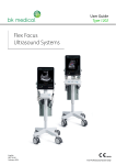
B/A and UBM Ophthalmic Ultrasound
User Manual
U.S. Federal Law requires that this device be used
only by or under the supervision of a physician.
621 W 20th Street, Hialeah, FL, 33010
Phone: 508-787-1400
Toll Free: 888-268-6756
UMN-000002 Rev. 2
Regulatory Notices
U.S. Federal Law requires that this device be used only by or under the supervision of a physician.
This device has been found to operate within the limits for a Class A digital device, and is not
intended for use in a residential environment.
This is a Class IIa medical device.
Electrical Safety: Class II Type B
Manufacturer:
Optos Hialeah
621 W. 20th Street, Hialeah, FL 33010, USA
Toll Free: 888-268-6756
Direct Line: 508-787-1400 (International)
Fax: 508-486-9310
Worldwide Corporate Office:
Optos Plc
Queensferry House
Carnegie Campus
Enterprise Way
Dunfermline
Scotland, UK
KY11 8GR
Tel: +44 (0)1383 843300
Fax: +44 (0)1383 843333
Optos North America Headquarters
Optos North America
67 Forest Street
Marlborough, MA 01752
USA
Call Toll-free (US & Canada): 1-800-854-3039
Outside of the US: +1 508 787 1400
2
UMN-000002 Rev. 2
Warranty Information
OPTOS warrants its products are free of defects of labor and material for two years for electronics, 1
year for probes. Associated computer systems carry a 1-year manufacturer’s warranty; extended
warranties are optionally available.
The following items are not covered:
•
•
•
•
•
Physical damage to the unit or probes due to misuse or shock
Damage or data loss due to power failures or fluctuations. The use of a lineinteractive UPS is recommended to avoid these types of failures.
Loss or corruption of data or software due to user error or the installation or
use of any third-party hardware or software.
Damage to transducers caused by autoclaving or exposure to excessive heat.
Repairs not covered by warranty will be invoiced on the basis of parts and
labour. At OPTOS’ discretion, the damaged component may be exchanged at
a flat rate.
Networking
OPTOS does not provide support for the operation of its products in a network environment.
Connection to and operation on any network is entirely the responsibility of the user. Where
installation or use of any network hardware or software interferes with the normal operation of the
OPTOS product, that product must be returned to normal operation at the user’s expense. When the
connection of an OPTOS product to or installation of OPTOS-supplied software on, a network
interferes with the operation of the network, the product must be removed from the network;
alternatively, the problem may be resolved by the user in cooperation with the network owner, at
their expense.
Third-Party Software
OPTOS does not provide support for the use or installation of any software obtained from a third
party on its products, including, but not limited to, operating system upgrades and device drivers.
When software not supplied by OPTOS interferes with the operation of the system, the product will
be returned to its original condition at the user’s expense.
OPTOS may occasionally furnish to users software not directly related to the functioning of its
products. Such software is supplied as is, without warranty of any kind, and the availability of support
for such software is at OPTOS’ sole discretion.
3
UMN-000002 Rev. 2
Standards and Regulations
•
FDA Approved # K092837
•
This device is a Class IIa medical device as defined by the European Medical Device
Directive (MDD)
•
The device complies with the EC Medical Device Directive 93/42/EEC
Warnings and Cautions
Warning:
Switching on a cold instrument near 0° Celsius will permanently damage it. Let the instrument reach a
normal room temperature for half a day to allow the internal elements to warm up and to avoid any
thermal shock hazards when switched on. The cover will quickly reach room temperature, but not the
internal circuitry.
Warning:
Unit is approved for operation only with the included power supply.
Warning:
Disconnect AC POWER before cleaning the case.
Warning:
Data will be saved under the same patient name until another has been selected.
Warning:
The transducers are fragile. Dropping or striking any probe can cause it to malfunction; handle all
probes with care. If a probe should be dropped, inspect it carefully for chips and cracks, and make a
test scan on a known object.
Warning:
This device is not intended for foetal use.
Caution
The console must not be disconnected from the computer while the system is running.
Caution:
The probe must be connected or disconnected only when the unit is switched OFF.
4
UMN-000002 Rev. 2
Warning:
Never autoclave a transducer or expose it to high heat.
Caution:
Follow the instructions included in this manual for disinfecting the transducer after each use.
Caution:
Applying excessive pressure to the probe will cause discomfort for the patient and distort the eye,
resulting in incorrect measurements.
Caution: Choosing the wrong vitreous material will create serious errors in the axial length and
calculation result in Biometry mode.
5
UMN-000002 Rev. 2
Introduction
This User’s Manual describes the OTI Scan 3000 B, A and UBM system hardware and software. This
page is a brief outline of the entire system. The functions described will not be available on every
system: the selection depends on the system configuration.
The software uses a tabbed interface: the user can select any of the primary functional modules at
any time by clicking on the tab for that function at the top of the screen. When there are several
major components in a function, these are presented as tabs below the principal tab bar.
The opening screen is generally the Patient Data screen. The operator is not required to identify the
patient before starting the examination; this can be done at any time during the exam, and, if no
patient has been selected when "Save" is clicked, the operator is automatically taken into the
database to select the appropriate patient record or create a new one. Warning: the same patient
will be used for all saves until another has been selected.
The patient information screen has been organised to display full information and a list of saved
examinations for the selected patient, summary information about the images is displayed, including
any notes on probe orientation that were recorded at the time the image was captured and saved.
When an exam is selected, a simplified view is presented, so that the user can review it. It is possible
to copy and delete saved examinations one at a time.
The printing system has been designed to use the default printer and provide access to the control
functions available from the printer drivers. Curves are printed in black on white, reducing ink
consumption.
6
UMN-000002 Rev. 2
Chapter 1
Characteristics
1
Description
The OTI Scan 3000 modular ultrasound system is an ultrasonic diagnostic system intended to be used
for ophthalmic applications.
Scans can be made in Immersion Mode or by placing the probe directly on the eye. UBM scans require
the use of an immersion cup.
The OTI Scan 3000 software runs on Windows, and uses the features of the Windows interface to
direct the operation of the system and maintain patient records, permitting a user-friendly
environment for clinical applications.
2
System Components
Depending on the configuration of the system, the OTI Scan 3000 system consists of the B-Scan
ultrasound unit, which contains the UBM/B-Scan ultrasonic pulsar/receiver and scan converter,
and/or an A-Scan ultrasound unit, which contains the A-Scan ultrasonic pulsar/receiver and scan
converter. The system may include a focussed B-scan probe operating at 10MHz, focussed biometry
probe operating at 13 MHz, diagnostic A-scan, and/or focussed 35 or 50MHz high frequency UBM
probes.
3
Application
To make a measurement, the operator first displays the acquisition screen, and follows the
instructions for its various controls. The probe is applied to the patient’s eye directly or using an
immersion cup. For biometry, there are two modes of operation, automatic and manual. In automatic
mode the system identifies the critical structures in the eye and makes the measurements. In manual
operation the operator must freeze an image and then select the points for the measurements. There
are optional settings for particular cases such as dense cataracts or silicone-filled eyes.
7
UMN-000002 Rev. 2
4
Specifications
a.
Dimensions
i. Console
1. 195 mm (l) x 116 mm (d) x 44 mm (h)
2. Weight: 0.6 kg
b. Power Supply
i. Console
1. Medical Grade Power Supply
2. Input Voltage range: 100-240V AC
3. Output Voltage: 12V DC
4. Frequency: 50/60Hz
5. AC power consumption: 18VA @ 120V
6. DC power consumption: 13W
c.
Operating conditions
i. Temperature:
1. Operating = 19 degrees to 35 degrees C (32 to 95 F)
2. Storage= -40 to 65 C (-40 to 149 F)
ii. Relative humidity:
1. Operating = 10% to 90% (non-condensing)
2. Storage: 5% to 95% (non-condensing)
8
UMN-000002 Rev. 2
d. Probes
i. Biometry
1. Reference: US-PRO-A
2. Frequency: 13MHz
3. Focal Length: 23mm
4. Operating mode: Pulsed
5. PRF: 10Hz
6. Active diameter: 3.5mm
7. Active surface: 9.6mm2
8. Axial resolution: 0.12mm
9. Minimum distance measured: 12mm
10. Maximum distance measured: 37mm
11. Acquisition
i. Horizontal resolution: 1020 points
ii. Vertical resolution: 256 points
iii. Linear resolution: 0.052mm
ii. B Scan
1. Reference: US-PRO-10
2. Frequency: 10MHz
3. Focal Length: 23mm
4. Operating mode: Pulsed
5. PRF: 3840 Hz
9
UMN-000002 Rev. 2
6. Active diameter: 7mm
7. Active surface: 154mm2
8. Axial resolution: 0.15mm
iii. Hi-Res B Scan
1. Reference: US-PRO-20
2. Frequency: 20MHz
3. Focal Length: mm
4. Operating mode: Pulsed
5. PRF: 3840 Hz
6. Active diameter: 7mm
7. Active surface: 154mm2
8. Axial resolution: 0.09mm
iv. High Frequency
1. Reference: US-PRO-35, US-PRO-50
2. Frequency: 35 or 50MHz
3. Focal Length: 13mm
4. Operating mode: Pulsed
5. PRF: 3072 Hz
6. Active diameter: 7mm
7. Active surface: 154mm2
8. Axial resolution: 0.0219 or 0.0153mm
9. Scan depth: 15mm
10
UMN-000002 Rev. 2
e. Acquisition
i. Vertical resolution: 1020 points
ii. Horizontal resolution: 256 lines
iii. Linear resolution: up to 14.6µm
f. Accuracy
i. Measurement accuracy depends on the probe frequency and the technique
employed. Maximum accuracy equals the axial resolution, assuming no errors
in technique
ii. IOL powers are displayed in increments of .25D, with refractive errors
estimated to .01D. For SRK II, a .2mm error in axial length yields a .5D error in
calculated refraction; for other formulas, a .5D error corresponds to a .15mm
error in the axial length.
11
UMN-000002 Rev. 2
5
ALARA Section and Emissions
Probe: Material: PZT
Nominal Center Frequency 13 MHz
Pulse repetition frequency: Hz
Type: A-scan, Energy emitted in bursts. Measurement must be repeated for new burst.
Ultrasonic Intensities in tissue: *
ISPTA, 0.0285mW/cm2.
ISPPA, 6.76W/cm2.
Mechanical Index
0.13
Ultrasonic power: 2.75µW
* At measured transducer focus (0.5 centimeters from probe tip)
The energy will always be attenuated by the tissue between the transducer and the focus when used
as recommended. The values presented here are the values at the focal point, the point of maximum
intensity.
It is not possible to vary the output energy of the transducer. However, to minimize exposure,
measurements should be kept as short as possible.
If more accuracy is desired, the intensity in the body at any transducer point may be calculated
according to the formula recommended by the FDA:
It = Iwexp (-0.069fz),
where It = is the estimated in situ intensity, Iw is the measured intensity in water at the focus of the
transducer (indicated in the above chart), f is the ultrasonic frequency in megahertz, and z is the
distance from the face of the probe to the transducer focus in centimeters, which is the point of
measurement. For this device, f = 12 and z = .500. This formula was also used to calculate the derated
values shown above.
12
UMN-000002 Rev. 2
Transducer parameters show considerable variation from transducer to transducer. The
measured and calculated values shown above were those for an actual transducer, whose values
deviated slightly from the values in the specification given, and whose values are likely to be different
from the transducer with your system. However, the values in the specification should give results
that are accurate enough for any practical purpose, since the intensities are very low.
One should always minimize exposure by limiting the ultrasonic transmission to as short
periods as possible.
Velocity of sound used by system: (values for different eyes)
Aqueous
1532
Vitreous
1532
Silicone Oil
990
Natural lens 1641
Silicone IOL 980
13
PMMA IOL
2718
Acrylic IOL
2120
UMN-000002 Rev. 2
A -Probe
14
UMN-000002 Rev. 2
10 MHz Transducer:
15
UMN-000002 Rev. 2
20 MHz Transducer:
16
UMN-000002 Rev. 2
35 MHz Transducer:
17
UMN-000002 Rev. 2
50 MHz Transducer:
18
UMN-000002 Rev. 2
STANDARD SYMBOLS
Attention, consult accompanying documents.
Dangerous voltage
Symbol type B equipment
Classe 1
Accessible conductive parts are connected to earth
Equipotential point
19
UMN-000002 Rev. 2
6
DESCRIPTION and CONNECTIONS
A. Front Panel A-Scan
Multi-function
control
A Probe
B. Rear Panel A-Scan
On/Off
Power In
20
USB port
Footswitch
UMN-000002 Rev. 2
C. Front Panel B-Scan
B or UBM Probe 2
B or UBM Probe 3
B or UBM Probe 1
B or UBM Probe 4
D. Rear Panel B-Scan
Power In
1394 Firewire
1394 Firewire
21
UMN-000002 Rev. 2
E. Probes and Accessories
10MHz & 20MHz B-Probe
A/Biometry Probe
22
UMN-000002 Rev. 2
35 and 50 MHz UBM Probes
The transducer is
removable for storage
and cleaning.
Do not store the probe
with the transducer
attached.
Power Supply
23
UMN-000002 Rev. 2
B Probe Cable
Probe Holder
24
UMN-000002 Rev. 2
A-Scan Footswitch
B-Scan/UBM or Combo Footswitch
25
UMN-000002 Rev. 2
Chapter 2
Set-up and Maintenance
1.
Setup
INSTALLATION
A.
a. Place OTI-Scan and computer on a flat surface. Position the system to ensure
that the operator will be comfortable during use
b. Before connecting consoles, ensure that software is properly installed. See OTI-Scan
3000 Software Installation Instructions.
c. Connect power supply to OTI-Scan and AC power. Connect computer to
AC power
d. Connect Firewire cable to OTI-Scan and computer
e. Connect all probes
f. Switch on the OTI-Scan, then switch on the computer
g. Install and connect printer in accordance with manufacturer’s instructions
B.
VENTILATION
Like other electronic equipment, the OTI-Scan 3000 produces heat, which must be
exhausted for correct system operation. Keep the unit away from walls to allow air
circulation and never cover the unit even partially (with protective cover, files etc.) during
use. It is particularly easy for laptop computers to overheat when used in confined spaces.
C.
PRINTERS
The OTI Scan 3000 is designed to use standard printers (the printer must be Windows
compatible). Print speed and quality will depend on the printer chosen. An inkjet printer will
provide better image quality; laser printers are faster and more economical to operate. In
general, the printer is not supplied. OPTOS can only offer limited assistance with the
installation of printers.
Printer Installation
All printers should be installed according to the directions in the user’s manual supplied with
the printer, using the correct Windows drivers. Drivers and driver installers for a limited
selection of printers may be pre-installed on the OTI Scan 3000.
26
UMN-000002 Rev. 2
2.
Maintenance
Cleaning
Clean the case with a damp cloth. Use appropriate products to clean the computer,
keyboard and monitor. Cables may be cleaned with a soft cloth and alcohol.
The probe holder should be washed with warm water and a mild detergent to prevent buildup of gel.
Probe handle and transducer:
The user must use the following procedures to clean the transducer and probe end daily.
Material:
Distilled water
Soft facial tissue
Photographic lens cleaning paper
Procedure:
Keep the transducer and probe connected, rinse the transducer and probe end
thoroughly with distilled water.
Wet a piece of soft facial tissue; absorb water remaining on the transducer surface and
probe end by without rubbing
Inspect carefully for salt build up on surfaces
If there are any salt crystals, wet lens cleaning paper with distilled water, and then very
lightly wipe clean any salt build up on the transducer surface.
If there is salt built up around the connector, remove the transducer from the probe,
and use lens cleaning paper remove the build up. Then reconnect the transducer and
hand tighten.
Rinse the transducer and probe top end with distilled water
Leave the transducer and probe to air dry.
27
UMN-000002 Rev. 2
Note:
This maintenance procedure is not intended for disinfection of the transducer and probe.
Disinfection must still be performed between patient exams, following the procedures
outlined below. Daily cleaning of the transducer and probe must be done at the end of the
working day, when no further exams are expected. If an emergency examination must be
performed outside normal working hours, the probe and transducer must be disinfected and
completely cleaned immediately afterwards.
Disinfection
The probe must be cleaned and disinfected between patients to prevent the transmission of
infections. It is the user’s responsibility to ensure that the relevant standards are maintained
and that the products and procedures are effective and appropriate for ophthalmic
applications. The following information is provided for the guidance of users, and specific
products are mentioned for illustration only; OPTOS does not endorse the use of these or
any other product. Products must be used in accordance with the manufacturer’s
instructions.
FOR U.S.A. ONLY
How to prevent patient-to-patient transfer of infection
The probe must be cleaned between two patients to prevent
patient-to-patient transfer of infection.
The probe may be cleaned using Cidex liquid disinfectant, usually
found in hospitals. Other FDA-cleared disinfectants may also be used.
Probes and cables can be immersed up to the connector.
Do not immerse the connectors.
Do not autoclave the probe or the cable.
After cleaning, rinse the end of the probe thoroughly with clean water
to remove all traces of the liquid used.
Follow the instructions on the label of the disinfectants.
The surfaces should then be dried with a lint-free cloth.
28
UMN-000002 Rev. 2
FOR EUROPE
PRECAUTIONS TO BE TAKEN TO AVOID THE SPREAD OF INFECTIOUS DISEASES,
PARTICULARLY CREUTZFELD-JACOB DISEASE, WHEN USING OPHTHALMIC ULTRASOUND
PROBES.
PREAMBLE
– The standard protocol must be used to ensure satisfactory decontamination –
predisinfection and disinfection of the probe after use.
– The risky patient protocol must be used to ensure satisfactory decontamination –
predisinfection and disinfection of the probe after use on a patient where there is a risk of
transmission of Creutzfeld-Jacob disease.
OPERATOR'S CLOTHING
– Single use overall.
– Disposable gloves, sterile for disinfection.
– Glasses and anti-projection masks.
EQUIPMENT
– Soft silk brush (surgical nail brush).
– 3 x 500 ml stainless steel (or plastic), autoclavable-soaking trays.
– Single use hand cloths (e.g. Kimwipes ®).
– Demineralized or distilled water.
PRODUCTS
– Cleaning/pre-disinfectant: Aniosyme ® P.L.A. (Company: ANIOS),
or pre-disinfectant: Alkazyme ® alcalin (Company: ALKAPHARM).
The products must be diluted at 0.5% with warm water (25°C - 30°C) from
the tap or distilled water. The contents of the tray must be changed every day.
– Disinfectant type Alkacide ® (Company ALKAPHARM).
The product must be diluted at 5% with distilled water.
The solution must be changed every day.
– 6 Chlorometric degree solution of sodium hypochloride at 20°C.
The contents of the tray must be changed after each use.
– Demineralized or distilled water.
REMINDERS
– Disconnect the probes from the machines.
Machines MUST BE TURNED OFF before disconnecting probes.
Warning: Avoid splashing liquids onto probe connectors (end of the cable
which is connected to the machine).
29
UMN-000002 Rev. 2
PREPARATION OF DECONTAMINATION AGENTS
A) DECONTAMINATION • PREDISINFECTION AGENTS
- Proteolytic enzyme based agents (2 possibilities)
1 - 0.5% ALKAZYME solution in water (20g packet).
Prepare according to manufacturers instructions. The Alkazyme solution can be used for 8
days if kept in a sealed flask. The solution can also be made up in a 4 L recipient using
distilled water and fill up the soaking tray from there.
OR:
2 - 0.5% ANIOZYME solution in water (25g packet).
Prepare according to manufacturers’ instructions. The Aniozyme solution lasts 1 day in a
sealed flask.
B) DISINFECTION AGENT
1 - 5% ALKACIDE solution in water
Prepare according to manufacturers’ instructions
The Alkacide solution will keep for 8 days in a sealed flask.
Fill soaking tray (500ml) when disinfection is necessary.
C) RENEWING CONTENTS OF SOAKING TRAYS
For frequent use, the contents of the trays should be replaced at the beginning of the
morning and at the beginning of the afternoon. Wait 10 minutes after the last
decontamination before emptying out the Alkazyme or Aniozyme solutions.
30
UMN-000002 Rev. 2
Standard Protocol
31
1.
Immerse the probe and the cable (except for the connector) in a solution of either
ALKAZYME or ANIOZYME for 5 to 15 minutes depending on the perceived level of risk.
2.
Clean the probe and the cable in the chosen solution for 1 minute using the brush.
3.
Rinse the probe and the cable in de-mineralized or distilled water. Do not wet the
connectors.
4.
Dip the probe and the cable in the Alkacide solution for 5 to 20 minutes depending on the
estimated level of risk. Do not wet the connectors.
5.
Rinse the probe and cable with de-mineralized or distilled water. Keep the connectors dry.
6.
Dry with a sterile compress or a single use dry wipe if the rinsing water was sterile.
7.
The probe is ready for use.
UMN-000002 Rev. 2
Protocol for High-Risk Patients:
Reminder:
Disconnect the probes from the machines. Machines must be turned off first. Avoid any contact
between liquids and the electrical connectors at the ends of the probes.
Decontamination – Pre-disinfection: Immerse the probe and the cable (except for the connector) in a
solution of either ALKAZYME or ANIOZYME for 5 to 15 minutes depending on the perceived level of
risk.
Clean the probe and the cable in the chosen solution for 1 minute using the brush. Do not splash the
connectors
Rinse the probe and the cable in de-mineralized or distilled water. Do not wet the connectors.
Immerse the probe and the cable (except for the connector) in a 6 chlorometric degree solution of
sodium hypochloride for 60 min at 20°C ensuring the connectors are kept dry.
Rinse the probe and cable with de-mineralized or distilled water.
Immerse the probe and the cable (except for the connector) in the ALKACIDE solution for 15 minutes
Rinse the end of the probe with de-mineralized or distilled water. Keep the connectors dry.
Dry with a sterile compress or a single use dry wipe if the rinsing water was sterile.
Reminder:
The contents of the trays should be allowed to stand 10 minutes after disinfection is complete before
replacement.
32
UMN-000002 Rev. 2
Chapter 3
Operation: Basic Functions
The operation of the OTI Scan 3000 revolves around the computer and monitor. All functions are
controlled through the screen and the computer and all results are displayed on the monitor screen.
The system includes a holder and calibration block for the probes.
At the start of an examination, the operator sees the Patient List, which allows selection of
examination mode or access to patient files. The scan being taken appears on the acquisition screen.
The scan can be frozen or unfrozen on this screen by using the mouse or foot switch. "Buttons" on the
screen permit storage of the scan, freezing, printing, and measurements. Moving markers to various
anatomical points makes measurements. The distances between these markers are then indicated on
the screen. In biometry, the measurement may also be taken automatically, by choosing automatic
freeze on the Acquisition screen.
When a function is not available, the corresponding control is greyed out, and doesn’t respond.
This panel, in the upper right corner of each screen,
shows the current patient, the date and time, and
the current assignment of the footswitch pedals. In
this case, pressing the left pedal saves the current
scan and pressing the right pedal will start a new
scan – clicking on them will have the same effect as
pressing the pedal does.
33
UMN-000002 Rev. 2
The General Controls panel contains functions that are common to multiple scanning and viewing
modules:
Print Screen sends the current scan to the printer, providing quick output
where a full report is not desired.
Generate Report copies the current view to the Report module, where
observations, comments and diagnostic evaluation can be added.
Additional images can be inserted from the clipboard when it is enabled.
Copy to Clipboard and Snapshot options are available
The measurement mode and scan mode lists will offer the options that
are available in the current scanning module.
Zoom zooms the image 4x
Color Display generates a false-colour image.
Many functions require information
about the eye that was scanned. If this
has not been entered, starting these
operations will open a dialog requesting
that the eye be specified. This can be
done by clicking on the button or
pressing the corresponding footswitch
pedal.
34
UMN-000002 Rev. 2
Footswitches
A-Scan Footswitch
B-Scan and UBM Footswitch
For all B and UBM systems, the USB
footswitch shown to the left is supplied.
The left and right pedals have the
functions displayed on the footswitch
icon. The centre pedal acts like clicking
“OK” in a dialogue box, or it moves the
focus between any of the 4 slider controls
that are visible: Gain, Contrast, TGC and
the Frame Counter (See Page 38)
35
UMN-000002 Rev. 2
1. B Scan
Before starting a scan, transducers must be cleaned and disinfected. (See Pages 26-31)
The B scan module shows the image with a simultaneous A scan
profile. Start recording by clicking Live, or pressing the right footswitch;
end by pressing the right footswitch or pressing Stop. The recording
can be played back using the controls below the Frame Counter bar.
Particular frames are selected using the Left and Right buttons or
dragging the cursor along the bar. A specific section of the recording
can be selected for playback by placing the green Start and red Stop
markers inside the Frame bar. These are the frames that will be saved
to the patient’s folder if this option is available. The slider on the bar
indicates the position of the current frame in the recording, and can be
used to move through the sequence by clicking and dragging.
The A-Scan Vector/Profile cursor is the green and red line running through the B Scan image. The
Vector/Profile displays the intensity of the echoes in the image as a classic A-Scan curve. Clicking and
dragging its left end changes the
vertical position of the cursor. Clicking and dragging the right
end changes the angle.
The profile is displayed in the window below the image; linear
measurements
are
made by dragging the vertical cursors to the appropriate points on the
profile. The red section of the Profile cursor shows the interval being measured.
36
UMN-000002 Rev. 2
Change Velocity
To ensure accurate length measurements, the tissue velocity must be set to an
appropriate value for the eye being examined. Where there has been a
vitrectomy with silicone oil replacement, or the measurement range includes
other structures where the velocity differs from the normal 1532m/s, the
correct value can be entered by clicking Change Velocity, and entering the new
value in the dialog box. In complex cases, it may be necessary to make the
measurement in segments, entering a value for each segment. In this situation,
the Clipboard can be used to store each segment for inclusion in the report.
Caution: The velocity will be set at the new value until it is changed again or the
program terminates.
37
UMN-000002 Rev. 2
Select Probe Frequency
Transducer frequency and
sweep angle are selected
from the Probe list.
The probe may be applied directly to the eye or used with an immersion cup. To start a scan, place gel
on the probe and place the probe on the eye (or place the cup on the eye and fill with sterile saline),
and click on to start the transducer moving. Place the probe in the cup and move it towards the eye
until the cornea appears at the bottom of the image.
Caution! Applying excessive pressure to the probe will cause discomfort for the patient and distort
the eye.
Select Scanning Zone/Depth
Orbit mode: The normal scan depth is 37mm from the face of
the probe. Selecting Orbit improves visualization of deep
structures; the field of view is then 8-45mm
38
UMN-000002 Rev. 2
Image Adjustments
These three sliders control the TGC, brightness and contrast of
the image. When the image is live, they are set either by clicking
and dragging the slider with the mouse, or turning the control
knob on the console. The highlighted slider is currently being
controlled by the knob; it may be changed either by clicking
with the mouse, or by pressing & releasing the knob. These
controls must be adjusted to obtain the best image while
scanning; while they have the same visual effects on a frozen
image, it is important to remember that they are acting on
stored data. If the data is not captured when the image is made,
the detail cannot be created later by adjusting these controls.
Time Gain Compensation (TGC) corrects the image for the
natural attenuation of ultrasound in tissue. Less sound reaches
deep tissues, and the echoes are correspondingly weaker. This
is seen on the screen as a fainter echo, even when the tissue
has, in fact, the same reflectivity as one nearer the probe. The
TGC system compensates by applying more gain to late echoes
than early ones – ideally, it matches the extra attenuation
exactly. The degree of correction is set using the TGC slider. The
system will automatically set the end of the first zone at the
surface of the retina.
39
UMN-000002 Rev. 2
Measure B-Scan and UBM
Selecting Calipers replaces the Vector cursor
with a pair of linear cursors that allow linear
measurements of the image. The cursors are
placed by clicking on each end and dragging it
to the required point. They will move
independently, and there is no fixed relation
between them. In this mode the Profile
window is frozen.
Zoom and Color
Clicking on Color creates a false-color
rendering of the image. In B mode the color
table is fixed.
Clicking on Zoom displays ¼ of the original
image, magnified 2:1. The original image is
shown in the lower part of the screen, with a
box outlining the magnified area. Clicking
and dragging inside the box will slide it
over the image to select the area to be
magnified.
40
UMN-000002 Rev. 2
Select Probe Position / Scan Orientation
The Description field accepts a brief
description of the pathology and
identifies the eye that was scanned.
This information will be attached to
the file when Save Movie is clicked.
Position Marks
Indicate the probe position by
selecting the view, then clicking
on the correct location to show
the probe orientation.
Markers are provided for
transverse, longitudinal and axial
views.
41
UMN-000002 Rev. 2
2. High-Frequency B Scan (UBM)
Before starting a scan, transducers must be cleaned and disinfected. (See Pages 26-31)
To enter the UBM module, click on the UBM tab. Aside from the probe selection and measurement
functions, it is identical in operation to the B scan module.
Scans can be made using the 35 or 50MHz transducer the system offers an image sector of 18° as well
as the standard 34°, with twice the frame rate for the narrower sector. Click on Probe to select the
correct value for the connected probe:
The probes must be used with an immersion cup.
DANGER!
CONTACT BETWEEN THE MOVING TRANSDUCER AND THE EYE CAN CAUSE SEVERE INJURY. THE
USER MUST TAKE EVERY PRECAUTION TO PREVENT THE TRANSDUCER TOUCHING THE EYE.
42
UMN-000002 Rev. 2
To start
a scan, place the immersion cup on the eye and fill with sterile saline.
Click on
to start the transducer moving. Place the probe in the cup and
move it towards the eye until the cornea appears at the bottom of the image. Proceed with the
examination.
The UBM module shows the image with a simultaneous A scan profile.
Start recording by clicking Live, or pressing the right footswitch; end
by pressing the right footswitch or pressing Stop. The recording can
be played back using the controls below the Frame Counter bar.
Particular frames are selected using the Left and Right buttons or
dragging the cursor along the bar. A specific section of the recording
can be selected for playback by placing the green Start and red Stop
markers inside the Frame bar. These are the frames that will be saved
to the patient’s folder if this option is available.
Image Adjustment
These sliders control the contrast and brightness of the image. They
are set by clicking and dragging them with the mouse, or by pressing
the knob on the console to select the slider, and rotating the knob.
The highlighted slider is currently being controlled. These controls
must be adjusted to obtain the best image while scanning; while they
have the same visual effects on a frozen image, it is important to
remember that they are acting on stored data. If the data is not
captured when the image is made, the detail cannot be created later
by adjusting these controls.
When Show focus is checked, lines are projected on the image
indicating the focal zone of the transducer. This is the area where the
image resolution is best. As far as possible, the structure of interest
should be kept in this zone.
43
UMN-000002 Rev. 2
Zoom
Clicking on Zoom displays ¼ of the
original image, magnified 2:1. The
original image is shown in the
lower part of the screen, with a
box outlining the magnified area.
Clicking and dragging inside the
box will slide it over the image to
select the area to be magnified.
44
UMN-000002 Rev. 2
Measurements
There are five measurement modes in the HF
module: Vector 1550 is a cross-vector
measurement; Calipers gives two simultaneous
linear measurements on the image; Angle
measure, intended for measuring the anterior
chamber angle, displays the angle defined by
the cursors; Biometry measures distance along
the optic axis, using the correct sound velocity
for each segment; Chord measure is a special
biometry mode intended for certain types of
ocular implant.
Vector 1550
This is the default measurement mode. The
cursor is the green and red line running
through the image. Clicking and dragging its
upper end changes the horizontal position of
the cursor. Clicking and dragging the lower
end changes the angle. The profile is displayed
in the window below the image; linear
measurements, assuming an average tissue
velocity of 1550m/s, are made by dragging the
vertical gates to the proper points on the
profile. The red section of the Profile cursor
covers the interval being measured.
45
UMN-000002 Rev. 2
Calipers
Clicking on H-W measure replaces the Profile
cursor with a pair of linear cursors that allow
linear measurements of the image using a tissue
velocity of 1550m/s. The cursors are placed by
clicking on each end and dragging it to the
required point. They will move independently,
and there is no fixed relation between them. The
profile window is frozen in this mode.
For this image Color Display has been checked,
creating a false-color rendering of the image,
using a fixed color table.
Angle Measure
To measure the angle between two surfaces, such
as the anterior chamber angle shown above, check
the Angle Measure box.
The apex of the angle and the end points of the
sides are placed by clicking on them and dragging
to the correct location. The sides can be any
convenient length, but for the greatest accuracy
they should be as long as possible. With the
“lever” effect of a long arm, it is easier to make
small changes in the included angle. The
measurement is displayed below the apex.
46
UMN-000002 Rev. 2
Biometry
The Biometry module is intended
to provide accurate distance
measurements in the anterior
segment, particularly along the
optical axis. The components are
recognized automatically, and the
correct tissue velocities for each
component are used: 1641m/s
for the cornea and lens, and
1532m/s for the aqueous.
To make a measurement, use
Vector mode to place the cursor
on the axis, then click on the
measurement mode list and select
Biometry. The system will identify
the anterior and posterior surfaces
of the cornea and lens, and display
the gates on the curve. The gates
can be moved by clicking on them,
and dragging them to the desired
location.
47
UMN-000002 Rev. 2
Chord Measure
Anterior
lens marker
Chord Measure determines the
chord length from the center of
the corneal face to the sclera at
a level marking 1/3 of the
thickness of the lens.
Making a measurement requires
an image that clearly shows the
cornea, the anterior and posterior
lens, and the sclera. Position the
Profile cursor to trace the axis of
the cornea and lens. This should
give a profile similar to the one to
the left. If any of the peaks are
low, use another image.
Click on Chord Measure to display
the
cursors.
Ensure
that the marker is correctly
positioned on the anterior surface
of the lens. Drag the ends of the
upper horizontal line to place it on
the outer edges and parallel to the
iris. The ends of the lower line are
placed on the sclera. Verify that
the upper and lower ends of the
red vertical segment are on the
anterior face of the cornea and the
posterior face of the lens.
The chord lengths are displayed
beside the chords.
ATTENTION:
The scans and readings displayed are presented for purposes of illustration only.
They are not intended to represent “correct” or “normal” readings.
48
UMN-000002 Rev. 2
Description
The Description field accepts a
brief description of the
pathology and identifies the
eye that was scanned. This
information will be attached to
the file when Save Movie is
clicked
Scan Probe Orientation
Markers are provided for
longitudinal,
transverse
and axial views.
Indicate the probe position by
selecting the view, then clicking
on the correct location to show
the probe orientation.
49
UMN-000002 Rev. 2
3. Biometry
Before starting a scan, transducers must be cleaned and disinfected. See Pages 26-31.
The system should be calibrated regularly (See Page 50).
NOTE: It is the operator’s responsibility to place the probe properly, capture good scans and verify
proper positioning of the gates.
50
UMN-000002 Rev. 2
Calibration
The system should be calibrated at regular intervals.
Click
to open the Calibration window:
To calibrate the system, place the probe on the rear of the calibration block and click on Calibrate.
The system will measure the block ten times, and compare the average length
with the stored value. If the calibration succeeds, the window will display Calibrated and may be
closed. If the calibration fails, contact OPTOS immediately. The blue rectangle beside
the Calibrate button will turn green when the system is properly calibrated, or red if calibration fails.
Note: The test block will expand and contract with changes in ambient temperature.
If the unit is operated outside the specified temperature range, calibration may fail.
51
UMN-000002 Rev. 2
A-Scan Examination
1. In A mode, pressing the right footswitch will Start/Stop a scan. Pressing the left pedal will create a
Report.
Report
Live
2. Enter the Description and select the eye.
3. Click the corresponding tab to scan the other eye.
52
UMN-000002 Rev. 2
Select the lens/IOL type in the eye:
Default
If there are problems obtaining adequate scans because of a very mature cataract, click on Dense
Cataract.
NOTE: “Dense” mode offers a compromise between Log Amplification and Linear
Amplification. It provides higher echoes from main structures in the eye, such as
Anterior Lens (AL) and Posterior Lens (PL), as well as Retinal echoes, while lower echoes
are suppressed. In Biometry, it offers easier acquisition and display for patients with
dense cataract and/or a shallow anterior chamber. It also provides a better ratio
between the AL and PL echoes and the retinal echo.
•
•
•
•
53
Three options are offered for correcting for velocity variations in pseudo-phakic patients:
Ultrasound, Central Thickness and correction factor.
Ultrasound sets the tissue velocity for the lens to the correct value for the material and makes
the measurement by identifying peaks as in a normal eye.
To use Central Thickness, the user enters the thickness of the lens, as supplied by the
manufacturer, in the dialog, and this value is used to calculate the axial length.
If a fixed correction factor in diopters is entered, the correction will be applied to the calculated
refraction.
UMN-000002 Rev. 2
4. If the patient is a high myope, checking High Myopia will modify system presets and the scan
evaluation to improve ease of capture:
5. Select the desired scan technique:
Default
6. If the patient has had a total vitrectomy with silicone oil replacement, select the correct option in
the Vitreous box. This sets sound velocity in the vitreous to the proper value for the oil used.
Viscosity 1000cp
Viscosity 5000cp
Caution: Choosing the wrong vitreous material will create serious errors in the axial length and
calculation result.
54
UMN-000002 Rev. 2
7. Place the probe on the cornea, or in the immersion cup. When Live is clicked or the left footswitch
pressed, the system will start recording scans, keeping the best 9 that have been recorded. The height
of the scan is adjusted using the Gain slider, or with the knob on the console.
Caution! Applying excessive pressure to the probe will cause discomfort for the patient and distort
the eye, resulting in incorrect measurements.
The axial length is
displayed for each
scan, with its 3
components: the
anterior chamber, lens
and vitreous lengths.
The system records the data during scanning. For manual evaluation and capture of scans, this
recording can be played back using the standard controls: Start, Stop, Left, Right, Beginning and End.
A frame can also be found by dragging the cursor on the Frame Bar.
Next Capture will move to the next scan that the software identifies as acceptable.
The axial length is
displayed for each
scan, with its three
components: the
anterior chamber,
lens and vitreous.
The measurement cursors are positioned on the scan by clicking on them and dragging to the desired
point. Click on Add (see next page) to add the scan to the list. The yellow and blue horizontal bars on
the scale show the zones that are searched for the lens surfaces and retina. If the eye is unusually
small or large, the zones can be changed by dragging the ends to the left or right.
55
UMN-000002 Rev. 2
8. When the scans are acquired, they must be reviewed to ensure that they are of good quality.
Clicking on the length in the Axial Length window selects the scan and displays
it in the Axial Length Table Display window.
If Use Avg is checked, the average length will be used in the calculation. The average length and
standard deviation are shown at the bottom of the panel. Clicking on Remove will delete the scan.
Add includes the scan shown in the Recording View window. If more scans are needed, click on Live to
start scanning and acquire more.
The measurement on a scan shown in this window can be edited, in the same way as in Recording
View. The entry in the Axial Length table is updated automatically.
56
UMN-000002 Rev. 2
When a cursor is being
placed, the scan is
automatically zoomed
to that part of the
curve. This allows
accurate placement of
the cursor on the scan
Miniature views of
all the stored scans
a displayed in a 3x3
table.
Doubleclicking on a scan
will
switch
to
“selected
table
entry view” with
the selected scan
displayed in that
window.
57
UMN-000002 Rev. 2
9. Once a sufficient number of good scans have been acquired, the patient data must be entered. If
the axial length is already known, it can be entered directly.
AXL is the axial length of
the best scan or the average
of the acquired scans
10. Select the correct IOL and formula for the patient.
Clicking the Edit… button opens the Implants & Formulas window, where IOL constants and
formula/IOL combinations are set up. (See Page 59)
11. Click on Generate Report to create and open the report for editing (see page 65). This button will
not be active until all required information is entered. If both eyes have been scanned, data must be
entered for both, even if a calculation is only required for the second eye.
58
UMN-000002 Rev. 2
This button opens the TGC editor:
The values shown
generally give the
best results. As the
sliders are moved,
the
red
curve
displays the effects
of the changes
G
A
I
N
TIME/DEPTH
Time Gain Compensation (TGC) corrects the image for the natural attenuation of ultrasound in tissue.
Less sound reaches deep tissues, and the echoes are correspondingly weaker. This is seen on the
screen as a fainter echo, even when the tissue has, in fact, the same reflectivity as one nearer the
probe. The TGC system compensates by applying more gain to late echoes than early ones – ideally, it
matches the extra attenuation exactly. The gain levels for the anterior and posterior sections of the
scan are set by adjusting the zone boundaries and the gain in each zone for the best view of each
tissue. The initial and final gain values are set with Low Gain & High Gain; the position and width of
the transition between them are set using Transition Begin & Transition End. The settings will be
memorized. The sketch shows a typical TGC curve, with the sliders linked to the corresponding parts
of the curve.
59
UMN-000002 Rev. 2
IOLs and Formulas
The software includes a list of
available IOLs, with data provided
by the manufacturers. To select an
IOL,
double-click
on
the
manufacturer’s name to open a list
of IOL models, and highlight the
selected lens.
To alter the default IOL selections,
or add one not in the list, simply
enter the manufacturer, model,
type
(Anterior
or
Posterior
chamber), and the constants
obtained from the manufacturer,
then click on Update for an existing
lens, or Add for a new lens. Remove
deletes a selected IOL from the list.
Specific combinations of formulas
and IOLs are created by selecting
each from the individual lists, then
clicking Add. A combination is
deleted by selecting it from the
Implant+Formula list, then clicking
Remove.
60
UMN-000002 Rev. 2
4. Diagnostic A Scan
Click the Diagnostic A-Scan tab to enter A-Scan mode.
To record a scan, click on Live and placing the probe on the eye. Gain can be adjusted by turning the
knob on the console, or moving the Gain cursor with the mouse or footswitch. The scan data is
recorded in memory in a continuous loop, 10 seconds long. The moving cursor on the frame bar
shows which frame is being recorded.
To freeze, press the left footswitch, or click the mouse. The recording can be played back using the
controls below the Frame bar. Particular frames are selected using the Left and Right buttons or
dragging the cursor along the bar. To make a measurement, click on each calliper and drag it to the
required location.
The Description and General Controls are the same as in other modes: Print sends the displayed curve
to the printer; Generate creates a report, and Save stores the data in the patient’s folder.
61
UMN-000002 Rev. 2
Change Velocity
To ensure accurate length measurements, the tissue velocity must be set to an
appropriate value for the eye being examined. Where there has been a
vitrectomy with silicone oil replacement, or the measurement range includes
other structures where the velocity differs from the normal 1532m/s, the
correct value can be entered by clicking Change Velocity, and entering the new
value in the dialog box. In complex cases, it may be necessary to make the
measurement in segments, entering a value for each segment. In this situation,
the Clipboard can be used to store each segment for inclusion in the report.
Caution: The velocity will be set at the new value until it is changed again or the
program terminates.
62
UMN-000002 Rev. 2
5. Utilities
The Utilities module contains a number of functions that are opened by clicking their tabs.
The Preferences page has controls for editing the header and footer of the report pages and
controlling the display of various features in the software:
63
UMN-000002 Rev. 2
Selecting storage locations: Several functions offer the choice of selecting or changing the location
where a file will be stored. They will all open the same Windows dialog boxes, which are used to scroll
through the file system, open folders, and create new folders.
Folders are marked by a folder icon; data files are
usually marked with the icon of the program that
created them.
Click Save to save the file in the location listed in the
Save In: box.
The Export/Folders tab holds dialogs for changing the patient data folder and the file types used to
export data.
64
UMN-000002 Rev. 2
The Version Info tab
gives the current
software
version,
and provides the
serial number of the
console.
The Patient Log lists
the examinations
performed
each
day for the last
week. If required,
the list can be
printed.
65
UMN-000002 Rev. 2
Chapter 4
Reports
When the user clicks “Generate Report” in any mode, a properly formatted report will be created and
the Report module will be opened to edit and print it. The basic report is automatically saved to the
patient’s folder. Text can be added at any point in the document by clicking and typing; existing text is
changed by selecting it, and typing the new text. Clicking Save will save the changes to the file.
New creates a blank generic report, Delete erases the current report, Export saves the report as a
PDF file in the export folder (See Page 68), and Print sends it to the printer.
The basic editing functions are shown on the next page. The Insert buttons insert the selected image
or the entire contents of the clipboard into the current report. Three sample reports are included at
the end of the section. In the B scan report; a second image was copied from the Clipboard.
66
UMN-000002 Rev. 2
Clicking on any of the five tabs above the
report window opens editing controls
identical to those found in any basic text
editor. The user has complete control over
the appearance of the report.
Set font size
Set the style of the text
Set text
alignment
Choose the font
67
UMN-000002 Rev. 2
OTI-Scan Report
Patient Name:
Date:
Description:
Retinal Tear, Vitreous Hem
May 21, 2003
DEMO
Patient ID: 03007
OS
Comments: hemorrhage not clearly visible in all views
68
UMN-000002 Rev. 2
OTI-Scan Report
Patient Name:
Date of Image:
Description:
Intraocular, Lens
Jun 7, 2005
Patient ID: HF0005
OS
Axial Length: 26.59(mm)
Target Ametropia:0
Contact
Vac = 1532.00
Average: 27.11
K1: 43.2(D) K2: 42.9(D)
Phakic
Vl = 1641.00
StdDev: 0.27
Vv = 1532.00
AP961L* Allergan/Ioptex
Formula: SRK-T
A: 114.5
IPP601350 EUROCRYSTAL
Formula: SRK-II
A: 118.3
IOL (D)
7.50
8.00
8.50
9.00
9.50
10.00
10.50
11.00
11.50
Comments:
IOL (D)
10.50
11.00
11.50
12.00
12.50
13.00
13.50
14.00
14.50
69
REF (D)
1.72
1.34
0.96
0.57
0.18
-0.22
-0.62
-1.03
-1.44
REF (D)
2.08
1.58
1.08
0.58
0.08
-0.42
-0.92
-1.42
-1.92
UMN-000002 Rev. 2
OTI-Scan Report
Patient Name:
Date of Image:
Description:
Intraocular, Lens
Jun 7, 2005
Patient ID: HF0005
OS
Axial Length: 26.59(mm)
Target Ametropia:0
Contact
Vac = 1532.00
Average: 27.11
K1: 43.2(D) K2: 42.9(D)
Phakic
Vl = 1641.00
StdDev: 0.27
Vv = 1532.00
AP961L* Allergan/Ioptex
Formula: SRK-T
A: 114.5
IPP601350 EUROCRYSTAL
Formula: SRK-II
A: 118.3
IOL (D)
7.50
8.00
8.50
9.00
9.50
10.00
10.50
11.00
11.50
Comments:
IOL (D)
10.50
11.00
11.50
12.00
12.50
13.00
13.50
14.00
14.50
70
REF (D)
1.72
1.34
0.96
0.57
0.18
-0.22
-0.62
-1.03
-1.44
REF (D)
2.08
1.58
1.08
0.58
0.08
-0.42
-0.92
-1.42
-1.92
UMN-000002 Rev. 2
Chapter 5
Operation: Advanced Functions
1. Patient Management
The software will start showing the Patient List, with functions for the management of patient files.
To select a patient, click on the name to highlight it. The buttons on the left side of the
screen open the different file-management dialogs. To view the patient’s files, click on the File tab, or
on Open. Patient information and the case notes can be updated at any time by typing the new data
in the appropriate field and clicking Update.
71
UMN-000002 Rev. 2
Click New to open the dialog for creating a new patient folder:
The first three lines are required information. A Patient ID is automatically generated when the dialog
is opened: it should be replaced with the ID normally used in the practice.
Pathology
Pathology can be entered
directly in the field, or a
standard description
selected from the dropdown list.
72
UMN-000002 Rev. 2
Referring Physician
The name of the referring physician can be selected from the dropdown list. New names must be added through the Add Physician
dialog, which is opened by clicking Add. Edit opens the same dialog to
edit the e-mail entry.
Add Physician
The physician name and e-mail address are entered. Once entered, the
name cannot be edited. The e-mail address can be used to automatically email reports to the physician
73
UMN-000002 Rev. 2
Search for Patient
The first characters of the Patient ID or last name are entered in the search field.
ID searches are case-sensitive: strings must be entered as they appear in the
patient record. Clicking Search will list the patients matching the search
parameter in the Results: box; results can be sorted by clicking on the column
headers. Clicking on a patient, then Select, will open the patient entry.
If the patient isn’t found, clicking New will open the New Patient dialog so that a
new entry can be created.
To find a patient’s file, click Search to open the Search dialog. Enter the
search parameter in the correct box, and click Search to search the patient
list. It is possible to search for a particular patient, for all patients with a
particular pathology, for patients seen in a particular range of dates, for a
particular type of saved file or for all patients with a given text saved in
their exam results.
74
UMN-000002 Rev. 2
Search By Pathology
Text in the Pathology
field or Notes field can be
searched by entering the
search string in the
appropriate box.
Pathologies can also be
selected from the dropdown list. Clicking Search
will list the patients
matching the search
parameter in the Results:
box; results can be sorted
by clicking on the column
headers. Clicking on a
patient, then Select, will
open the patient entry.
Search by Last Exam Date
Search by Last Exam Date finds patients last seen in a particular period by entering the
start and end dates in either of the indicated formats. Clicking Search will list the
patients matching the search parameter in the Results: box; results can be sorted by
clicking on the column headers. Clicking on a patient, then Select, will open the patient
entry.
75
UMN-000002 Rev. 2
Search by File Type
Search by File Type finds all patients with particular files in their folders. Clicking
Search will list the patients matching the search parameter in the Results Box.
Results can be sorted by clicking on the column headers. Clicking on a patient,
then Select, will open the patient entry.
Search Reports
Any text string in a saved report can be entered in the search field. Searches in
this section are not case-sensitive. Clicking Search will list the patients matching
the search parameter in the Results: box; results can be sorted by clicking on the
column headers. Clicking on a patient, then Select, will open the patient entry.
76
UMN-000002 Rev. 2
Clicking Delete will delete the selected patient,
if the user clicks Yes in the confirmation dialog:
77
UMN-000002 Rev. 2
1. Files
When a Patient folder is opened, a list of the files saved for that patient is displayed.
When an image file has been selected in a
Patient Folder, a preview window opens with
basic information and controls. The image can
be reviewed to ensure the correct file is
selected. (See Page 81 for more information on
the Snapshot controls)
78
UMN-000002 Rev. 2
The controls beside the list will open, export, preview
or delete the selected file. When the clipboard is
enabled, Copy to Clipboard will copy the current frame
to the clipboard for use in a report.
Selecting Delete will open the
confirmation dialog.
Selecting Export will open
the dialog for selecting a
destination for the exported
file. Any volume mounted
by the Windows file system
may be used.
Once the desired location is
highlighted, clicking Save
will copy the file.
79
UMN-000002 Rev. 2
2. The Clipboard
The clipboard is used to store
individual B scan frames, A scan
curves and images recovered
from Snapshot files, for inclusion
in a report. The data can come
from alternative views of the
same patient, for a longitudinal
study or to gather all available
data on a complex case, or, from
different patients, for lateral
studies.
Images are saved on the
clipboard by clicking Copy to
Clipboard when the button is
visible. Clear will erase the
contents of the clipboard.
An image is selected by clicking
on it. Double-clicking will open
the annotation editor.
80
UMN-000002 Rev. 2
The clipboard image editor can be used to insert
markers in an image before it is included in a report.
Four pointers can be placed and arbitrary outlines
drawn. The image can also be zoomed 2X.
81
UMN-000002 Rev. 2
3. Snapshots
Snapshots are the only files that are edited directly in the Files view.
Once a snapshot has been marked up, it can be exported as an image file,
printed, used to generate a report or copied to the clipboard for inclusion
in another report.
The mark-up information will not be saved automatically. Click on Save As
New to save the changes to a new file.
Clicking on Reset Snapshot clears the changes.
82
UMN-000002 Rev. 2
To enlarge the image,
To highlight a
click Zoom. Clicking
region of interest,
on the image and
click on Draw.
dragging the mouse
Place the cursor on
will outline a
the image, then
rectangular area that
click on the mouse
will be enlarged. The
and
drag
the
enlargement depends
cursor to trace the
on path.
the area selected,
but scaling the image
too much will not give
a usable enlargement.
Clicking on A, B, C or D
creates a pointer that
can be positioned by
clicking and dragging on
the arrowhead or letter
83
UMN-000002 Rev. 2
The
Caliper
functions in the
same way as
the calipers in B
scan
(This image was
zoomed before
84
UMN-000002 Rev. 2
5. Archiving Data
Data must be archived to
ensure that it is not lost in the
event of a system failure.
Removing
infrequently
viewed files from the disk will
also improve performance
and free space. B mode
movies can be very large, and
the user can run out of disk
space
unexpectedly
if
archiving is not kept up to
date. The user can select the
period that files can be left
unused before being marked
for archiving.
The normal medium for
archives is CD-R, but any
external drive recognized by
Windows may be used.
Refresh Drive List can be used to locate a drive that is not recognized automatically, and add it to the list
of Archive drives.
The user determines how long files may be left unused by selecting the period from the Archive files: pick
list. If more than one drive is available for archiving, a similar list can be opened beside Archive Drive:
The system can be left to complete the archive operation and shut itself off if the Shutdown… box is
checked. Note: the files to be archived must fit on one disk for the operation to complete.
When all the options are selected, click on Archive to start the process.
85
UMN-000002 Rev. 2
Chapter 6
Background, Theory and Formulas
1. AXIAL LENGTH MEASUREMENTS
Steps for Accurate Biometry
IOL Power Calculations
BIOMETRY-AXIAL LENGTH MEASUREMENTS:
− Scan Capture: Capture at least 6-10 measurements (scans); review each of the captured images.
Select only the scans with a good echo pattern and delete the rest. At least 3–4 good scans with
an Axial Length standard deviation (SDAL) of 0.1 or lower should be saved and used for IOL
calculations. (The variation of the axial length, from the highest to the lowest, of the scans should
be
not
more
than
0.1-0.2mm.)
The software also indicates the anterior chamber depth standard deviation (SDac). This
information indicates to the user the degree of variation in the anterior chamber depth (AC)
measurements. Large variations in AC measurements indicate compression of the cornea and/or
off-axis positioning of the probe.
− Selecting the Best Scans: review each scan; verify the position of the 4 markers. Each marker
should be placed at the top of the echo. Observe the Retinal echo; it should be sharp (90 degree
from the baseline) with minimum amplitude height of 70% of the corneal echo.
The Anterior Lens and Posterior Lens echoes should also have a height of at least 70% of the
corneal echo. Note: in cases of dense cataract, the posterior lens echo will be lower than the
Anterior Lens echo due to absorption of sound by the opaque lens.
Pay attention to the Anterior Chamber Depth (ACD). The operator should save the measurements
with longest ACD. These are usually the measurements where there was minimum corneal
compression. (An off-axis probe position may also produce a longer ACD, however in this case the
retinal echo will be of poor quality).
− Dense Cataracts: In a dense cataract, additional low echoes might appear between the Anterior
Lens and the Posterior Lens echoes. Some reverberations of the Anterior and/or posterior Lens
echoes might be present in the vitreous when the cataract is very dense especially when higher
Gain is needed in order to capture the retinal echo. Note: make sure that the markers are
positioned on the principal Anterior and Posterior lens echoes and not on the repetitions in order
to avoid error in measurements. In a very dense cataract the user may need to increase the gain
setting in order to achieve good retinal echo. This is due to the higher absorption of sound in the
dense lens.
−
86
Silicone Oil-filled eye: In the case a of silicone oil-filled eye, the tissue velocity must be corrected.
UMN-000002 Rev. 2
If oil was placed in the vitreous and the posterior capsule is intact, replace the Vitreous Tissue
velocity (1532 m/sec) with 980 m/s in the User Screen in the Biometry X-Mode. If the lens was
also removed, you must replace the lens tissue velocity of 1641 m/s with the velocity in silicone oil
(980 m/sec.). If the Anterior chamber is also filled with oil, the correct velocity must be typed in
place of 1532 m/s, which is the tissue velocity in the Aqueous.
− Pseudo-phakic eyes: when measuring eyes that have previously undergone cataract surgery, the
tissue velocity must be corrected for the implanted IOL. The tissue velocity for PMMA IOL is 2718
m/s, for Acrylic IOL is 2120 m/s and for Silicon IOL its 1049 m/s. Please note that these values are
averaged between different IOL manufacturers. Small variations of IOL tissue velocity between
different manufacturers will not effect the reading substantially. If the user is not sure what kind
of IOL was implanted, an observation of the retinal echo distance may help.
C
AL
PL
R
Good scan,
markers
placed at the
peak of each
echo
Poor scan: off-axis
scan, AL echo too
low, retina echo
too low, front of
retina not
perpendicular to
the base line,
retinal marker off
to the right.
If either the AL or Retinal echo is too low, it is an indication that the probe is off the visual axis. The
axial length may be either too short or too long.
Note: The first marker (Cornea) will be to the right of the initial peak, which is the front of the
transducer. The tip of the probe will be to the right of this.
87
UMN-000002 Rev. 2
IOL Formulas
VARIABLES USED:
Variables in any formula:
AL:
Axial length.
K:
Averaged dioptric power of the cornea = (K1 + K2 / 2)
R:
Corneal curvature in mm = 337.5 / K (K in Dioptres)
ACD:
Post-Operative Anterior Chamber Depth,
S.R.K.- T:
Retinal thickness: Rethick = 0.65696 - 0.02029 x AL
Lc = AL except if AL > 24.2, Lc = -3.446 + (1.716 × AL) - (0.0237 × AL2)
K = 337.5 / R
R = 337.5 / K
C1 =-5.40948 + 0.58412 ×Lc + 0.098 × K
Rc=[R2 -(C1)2/4]
If Rc < 0 then Rc = 0
C 2 = R − Rc
ACD = 0.62467 × A - 68.74709, where A= SRK Constant
ACDE = C2 + ACD - 3.3357
n1 =1.336
n2 = 0.3333
LO = AL + Rethick = 0.97971 × AL + 0.65696
S1 = LO-ACDE
S2 = n1x Kd - n2 × ACDE
S3 = n1 x Kd - n2 x× LO
S4 =12x83 + LO×Kd
S5=12xS2 + ACDE ×Kd
REF _ X =
1336 × S 3 − IOL × S1× S 2
1.336 × S 4 − 0.001IOL × S1× S 5
IOL _ FOR _ TGT =
88
1336( S 3 − 0.001REFt × S 4)
1.336S 4 − .0001REFt × S 5
UMN-000002 Rev. 2
S.R.K.-II :
EMMETROPIC POWER:
P = A - 2.5AL - 0.9K + C
C = Correction to the first S.R.K. formula where C=0.
If AL < 20 mm
then
C=+3
If 20 <= AL < 21
then
C=+2
If 21 <= AL < 22
then
C=+1
If 22 <= AL < 24.5
then
If AL >= 24.5
then
C= 0
C = - 0.5
SRK-II: AMETROPIC POWERS :
with: P = Emmetropic power
I = Desired implant power
Rt = Target Refraction
Rf = Refraction factor.
Refraction = Vs (I) :
Rt=(P-l)/Rf , where
Rf=1.25
if P> 14
Rf=1
if P ≤ 14
Implant = Vs (Rt):
I = P - (Rt×Rf), where Rf = 1.25
Rf=1
89
if P > 14
if P ≤ 14
UMN-000002 Rev. 2
BINKHORST II:
VARIABLES
LB : AXIAL LENGTH CORRECTED FOR BINKHORST II.
Lb= LA+0.1984 mm
ACD-B : ANTERIOR CHAMBER CORRECTED FOR POSTERIOR CHAMBER LENSES
If Lb < 26 then ACD-b = ACD x (LA / 23.45)
If Lb >= 26 then ACD-b = ACD x (26 / 23.45), or ACD-b =1.1087 x ACD
R: Cornea curvature in mm = 337.5 / K (K in Diopters)
Ref: Target Refraction
Lb: Corrected Axial length.
AC: POST OPERATIVE ANTERIOR CHAMBER
AC = ACD for Anterior Chamber lOLs
AC = ACD-b for Posterior Chamber lOLs.
FORMULA GIVING THE IMPLANT VALUE VERSUS THE DESIRED REFRACTION : REF
IOL = Vs (Ref) if Ref =0 IOL= IOLem (emmetropia)
IOL =
1336 [1.336R - 0.3333Lb - 0.001 Ref (16.032R - 4Lb + Lb × R) ]
(L - AC) [1.336R - 0.3333AC - 0.001 Ref (16.032R - 4AC + AC × R)])
1336 [ 1.336R - 0.3333Lb - 0.001 Ref (16,032R - 4Lb + Lb.R) ]
FORMULA GIVING THE REFRACTION VERSUS THE DESIRED IMPLANT IOLAM
Ref = Vs (IOL)
Ref =
90
1336[1.336 R − 0.33L] − IOL[ Lb − AC ][1.336 R − 0.3333 AC ]
1.336[16.032 R − 4 L + L × R ] − 0.001IOL[ Lb − AC ][16.032 R − 4 AC − AC × R ]
UMN-000002 Rev. 2
HOLLADAY:
VARIABLES :
R: Cornea curvature in mm = 337.5 / K (K in Diopters)
Ref: Target Refraction
LH - AXIAL LENGTH CORRECTED FOR HOLLADAY.
Lh = AL + 0.200 mm
SF - SURGEON FACTOR: SPECIFIC FOR HOLLADAY FORMULA.
SF = (A x 0.5663) - 65.60 where A is the SRK Constant
ACH - ANTERIOR CHAMBER CORRECTED FOR HOLLADAY.
Rag = R, except that if R < 7mm then Rag = 7 mm
AG = (12.5 / 23.45) AL , except that if AG > 13.5 then AG = 13.5 mm
ACD = 0.56 + Rag − Rag 2 − AG 2 / 4
ACh = ACD + SF
FORMULA GIVING THE IMPLANT VALUE VERSUS THE
DESIRED REFRACTION (OR AMETROPIA): REF
IOLam = Vs (Ref)
if Ref =0 IOLam = IOLem (emmetropia)
IOLam =
1336 [1.336R - 0.3333L h - 0.001 R ef (16.032R - 4L h + L h × R) ]
(L h - A Ch ) [1.336R - 0.3333A Ch - 0.001 R ef (16.032R - 4A Ch + A Ch × R)])
FORMULA GIVING THE REFRACTION VERSUS THE DESIRED IMPLANT: IOLam
Ref = Vs (IOLam)
R ef =
91
1336[1.336 R − 0.33Lh ] − IOLam[ Lh − ACh ][1.336 R − 0.3333 ACh ]
1.336[16.032 R − 4 Lh + Lh × R] − 0.001IOLam[ Lh − ACh ][16.032 R − 4 ACh + ACh × R]
UMN-000002 Rev. 2
HOFFER-Q:
VARIABLES :
P:
Implant POWER (D)
R:
Refractive error at corneal plane (D).
Rx:
Desired ametropia : Refractive error at spectacle (D).
K:
Average Keratometry (D)
CD:
Corrected Chamber Depth (mm).
ACD: Anterior chamber depth from the personalized IOL User file.
AL:
Axial Length (mm)
CORRECTED CHAMBER DEPTH :
If AL<=23, M=+1 and G=28
If AL>23, M=-1 and G=23.5
If AL>31, AL=31
If AL<18.5, AL=18.5
CD = ACD + 0.3( AL − 23.5) + tan 2 K + 0.1M ( 23.5 − AL) 2 × tan[0.1(G − AL) 2 ] − 0.99166
EMMETROPIA POWER :
R=Rx/(1-0.012Rx)
P = [1336 / (AL - CD - 0.05)] - {1.336 / [(1.336 / (K + R)) - ((CD + 0.05) / 1000)]}
FORMULA GIVING THE REFRACTION (RX) VERSUS THE DESIRED IMPLANT: IOLAM
Rx = vs (IOLam)
R=
1.336
1.336
CD + 0.05
+
1336 /( AL − CD − 0.05) − IOLam
1000
−K
Rx=R/(1 +0.012R)
92
UMN-000002 Rev. 2
SPECIAL CONSIDERATIONS FOR UNUSUAL CASES
by: H. John Shammas, M.D.
Clinical Professor of Ophthalmology
U.S.C. School of Medicine, Los Angeles, CA.
Concurrent Astigmatic Keratectomy:
− Subtract 0.25D from the pre-op Ks for every diopter of the astigmatism to be corrected.
After Refractive Keratectomy:
− Refractive History Method:
Subtract the change at the corneal plane induced by the refractive surgery from the average corneal
power measured before the Keratectomy.
− Contact Lens Method
− Adjustment Method:
subtract 0.25D from the Ks for every diopter of myopia corrected.
PIGGYBACK IMPLANTS:
Error (+)
(+) Refractive Error = 0.03 (138.3-A) -0.5
Error (-)
(-) Refractive Error = 0.04 (138.3-A) -0.5
93
UMN-000002 Rev. 2