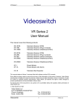
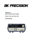
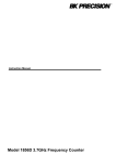
1
Model: 1657
AC Power Source
USER MANUAL
Safety Summary
The following safety precautions apply to both operating and maintenance personnel and must be
observed during all phases of operation, service, and repair of this instrument. Before applying power,
follow the installation instructions and become familiar with the operating instructions for this
instrument.
If this device is damaged or something is missing, contact the place of purchase immediately.
This manual contains information and warnings that must be followed to ensure safe operation as well
as maintain the meter in a safe condition.
GROUND THE INSTRUMENT
To minimize shock hazard, the instrument chassis and cabinet must be connected to an electrical
ground. This instrument is grounded through the ground conductor of the supplied, three-conductor ac
power cable. The power cable must be plugged into an approved three-conductor electrical outlet. Do
not alter the ground connection. Without the protective ground connection, all accessible conductive
parts (including control knobs) can render an electric shock. The power jack and mating plug of the
power cable meet IEC safety standards.
DO NOT OPERATE IN AN EXPLOSIVE ATMOSPHERE
Do not operate the instrument in the presence of flammable gases or fumes. Operation of any electrical
instrument in such an environment constitutes a definite safety hazard.
KEEP AWAY FROM LIVE CIRCUITS
Instrument covers must not be removed by operating personnel. Component replacement and internal
adjustments must be made by qualified maintenance personnel. Disconnect the power cord before
removing the instrument covers and replacing components. Under certain conditions, even with the
power cable removed, dangerous voltages may exist. To avoid injuries, always disconnect power and
discharge circuits before touching them.
DO NOT SERVICE OR ADJUST ALONE
Do not attempt any internal service or adjustment unless another person, capable of rendering first aid
and resuscitation, is present.
DO NOT SUBSTITUTE PARTS OR MODIFY THE INSTRUMENT
Do not install substitute parts or perform any unauthorized modifications to this instrument. Return the
instrument to B&K Precision for service and repair to ensure that safety features are maintained.
WARNINGS AND CAUTIONS
WARNING and CAUTION statements, such as the following examples, denote a hazard and appear
throughout this manual. Follow all instructions contained in these statements.
A WARNING statement calls attention to an operating procedure, practice, or condition, which, if not
followed correctly, could result in injury or death to personnel.
A CAUTION statement calls attention to an operating procedure, practice, or condition, which, if not
followed correctly, could result in damage to or destruction of part or all of the product.
WARNING: Do not alter the ground connection. Without the protective ground connection, all
accessible conductive parts (including control knobs) can render an electric shock. The
power jack and mating plug of the power cable meet IEC safety standards.
WARNING: To avoid electrical shock hazard, disconnect power cord before removing covers. Refer
servicing to qualified personnel.
CAUTION: Before connecting the line cord to the AC mains, check the rear panel AC line voltage
indicator. Applying a line voltage other than the indicated voltage can destroy the AC line
fuses. For continued fire protection, replace fuses only with those of the specified voltage
and current ratings.
CAUTION: This product uses components which can be damaged by electro-static discharge (ESD).
To avoid damage, be sure to follow proper procedures for handling, storing and
transporting parts and subassemblies which contain ESD-sensitive components.
WARNING
HAZARDOUS VOLTAGES IN EXCESS OF 230 Vrms, 400 V peak MAY BE PRESENT WHEN
COVERS ARE REMOVED.QUALIFIED PERSONNEL MUST USE EXTREME CAUTION WHEN
SERVICING THIS EQUIPMENT. CIRCUIT BOARDS, TEST POINTS, AND OUTPUT VOLTAGES
MAY ALSO BE FLOATING ABOVE (BELOW) CHASSIS GROUND.
CAUTION:
Before applying power verify that the product is set to match with the line voltage. Ensure that the AC
power line ground is properly connected to the AC Source input connector. Similarly, other power
ground lines including those to application and maintenance equipment MUST be properly grounded for
both personnel and equipment safety.
Always ensure that AC input power is de-energized prior to connecting or disconnecting the power
cable. Similarly, the AC Source mains switch must be switched OFF prior to connecting or
disconnecting LOADS.
In normal operation, the operator does not have access to hazardous voltages within the chassis.
However, depending on the application configuration, HIGH VOLTAGES HAZARDOUS TO HUMAN
SAFETY may be normally available on the output terminals if it is connected to a load. The User must
ensure that the Source Output lines are properly labeled as to the SAFETY HAZARDS and any that
inadvertent contact with hazardous voltages is eliminated.
For authorized service technicians only: Guard against risks of electrical shock during open cover
checks by NOT TOUCHING any portion of the electrical circuits. Even when power is OFF, capacitors are
well known to retain an electrical charge. Please allow sufficient time for discharge of storage elements
before opening the cover. Use SAFETY GLASSES during open cover checks to avoid personal injury by
any sudden component failure.
Always replace the fuse with the appropriate rating only. Do not operate the instrument in the presence
of flammable gases or fumes.
2
TABLE OF CONTENTS
Safety Summary ..................................................................................................................................................... 1
CHAPTER
1 ................................................................................................................................................ 4
1.1
INTRODUCTION ................................................................................................................................ 5
1.2
FEATURES .......................................................................................................................................... 5
1.3
SPECIFICATIONS ............................................................................................................................... 5
CHAPTER
2 ................................................................................................................................................ 7
2.1
INTRODUCTION ................................................................................................................................ 8
2.2
UNPACKING ....................................................................................................................................... 8
2.3
INPUT POWER REQUIREMENTS .................................................................................................... 8
2.4
INSTALLATION.................................................................................................................................. 9
2.5
TEST EQUIPMENT REQUIREMENTS ........................................................................................... 10
2.6
PACKAGE CONTENTS .................................................................................................................... 10
CHAPTER
3 .............................................................................................................................................. 11
3.1
FRONT PANEL DESCRIPTION ....................................................................................................... 12
3.2
REAR PANEL DESCRIPTION ......................................................................................................... 12
3.3
INITIAL CHECK ............................................................................................................................... 13
3.3.1
Default Settings .............................................................................................................................. 13
3.3.2
Initial Display ................................................................................................................................. 13
3.4
OPERATING INSTRUCTIONS IN LOCAL MODE ........................................................................ 14
3.4.1
Setting Voltage and Frequency ....................................................................................................... 14
3.4.2
Local Mode setting. ........................................................................................................................ 16
3.4.3
Range Selection .............................................................................................................................. 16
3.4.4
Alarm .............................................................................................................................................. 16
CHAPTER
4 .............................................................................................................................................. 17
4.1
RS232C INTERFACE ........................................................................................................................ 18
4.2
CONNECTION DETAILS ................................................................................................................. 18
4.3
REMOTE PROTOCOLS .................................................................................................................... 19
CHAPTER
5 .............................................................................................................................................. 28
5.1
MAINTENANCE ............................................................................................................................... 29
5.2
TROUBLESHOOT GUIDE................................................................................................................ 29
SERVICE INFORMATION ................................................................................................................................. 31
LIMITED ONE-YEAR WARRANTY ................................................................................................................ 31
CHAPTER
1
General Information
1.1 INTRODUCTION
1.2 FEATURES
1.3 SPECIFICATIONS
1.1
INTRODUCTION
The 1657 is an AC power source that provides high conversion efficiency and
low distortion output. It has a universal line output terminal and has a built in
PFC to provide an input power factor of 0.99 at full load. The output AC provides
up to 1500 VA and can be set to two voltage ranges, 135 V and 270 V. Front
panel buttons and control knob is available for quick voltage and frequency set.
A RS232 interface port is provided in the rear panel for remote programmability.
1.2
FEATURES
•
•
•
•
•
•
•
•
•
1.3
Low distortion sine-wave output with programmable frequency and
voltage.
Selectable two output voltage ranges: 135VAC or 270VAC
Settable frequency from 45Hz to 450 Hz.
Built-in torroidal isolation transformer.
Automatic protection against overload, short circuit and over
temperature.
Bright VFD display
Remote Programming through RS 232 serial interface.
Built in PFC provides 0.99 input power factor.
Conforms to EN 55022, class A, safety standard EN 60950.
SPECIFICATIONS
The operation specifications are listed below. All specifications are tested at the
output terminal, with temperature at 25 °C ± 5°C, nominal input of 120V
AC/230V AC and output of 250VAC/125VAC, and at 50Hz/60Hz with a resistive
load.
Model
Voltage
Frequency
Current
Power factor
Efficiency
Output Power
Maximum Power
Accuracy
Resolution
Output Voltage
1657
INPUT
90 – 264 VAC single phase
100 – 264 VAC for continuous full load operation
47 – 63 Hz
20A Max.
0.99 typical. @115 VAC 60 Hz, Full Load
> 85% at full load & nominal line input
OUTPUT
1500 VA
+/- 2% of F.S.
1W
5
Low Range
High Range
Accuracy
Resolution
Distortion
0 - 135 Vrms
0 - 270 Vrms
+/- 1% of F.S.
0.1 V
< 2% @ 220 VAC, 50 Hz Full Load
Worse case: < 5% @ 270VAC, 450 Hz, Full Load
+/- 0.1% of F.S.
+/- 1% of F.S.
0.05% per °C from 25 °C
Line Regulation
Load Regulation
Temp Coefficient
Output Current
Low Range (135 V)
12 Arms (Limited to 1500 VA)
High Range (270 V) 6 Arms (Limited to 1500 VA)
Accuracy
+/- 1% of F.S.
Resolution
0.01 A
Crest Factor
3
Power Factor
0.8 Lag to 0.8 Lead
Output Frequency
Range
45 – 450 Hz
Accuracy
0.2% of F.S.
Resolution
0.01 Hz
Supplemental Characteristics
Protections
Output Trip with Alarm indication for OL, SC,
OTP
Output Connection
Universal socket
Cooling
Internal force cooling
Note: Provide sufficient space around air inlets
and outlets for proper cooling
Approx. 24 kg (53 lbs)
Weight Approx.
Dimensions
88.0 mm (H) x 482.6 mm (W) x 500.0 mm (D)
3.46” (H) x 19” (W) x 19.7” (D)
Safety & EMC
EN 60950 & EN55022 Class A
Environmental Conditions
Operating
0 – 45 ° C
Temperature
Storage
-20 to +60° C
Temperature
Humidity
< 90% non-condensing
6
CHAPTER
2
Installation
2.1
2.2
2.3
2.4
2.5
2.6
INTRODUCTION
UNPACKING
INPUT POWER REQUIREMENTS
INSTALLATION
TEST EQUIPMENT REQUIREMENTS
PACKAGE CONTENTS
7
2.1
INTRODUCTION
The 1657 is configured, calibrated and tested prior to shipment.
This
instrument is therefore ready for immediate use upon receipt. The initial
physical inspections should be made to ensure that no damage has been
sustained during shipment.
2.2
UNPACKING
Inspect the shipping container before accepting it from the carrier. If damage
to the container is evident, remove the instrument from the container and
visually inspect it for damage to the instrument case and parts.
If damage to the instrument is evident, a description of the damage should be
noted on the carrier's receipt and signed by the driver or carrier agent. Save all
shipping containers and material for inspection. Forward a report of any
damage to the factory or the agent through which the unit is procured.
Retain the original packing container if subsequent repackaging for return to
the factory were required. Repackaging is straightforward and is essentially
the reverse of the unpacking.
Should only a sub-assembly need to be
repackaged for re-shipment, use the original containers.
Remove the Source module from its shipping container and inspect for any
damage to the front panel switches and display module. Check the rear of the
instrument for damage to Sockets, Fuse Holders and Terminals etc. Also check
for any optional parts, which have been ordered by you. If any of the part is
damaged or broken then DO NOT switch-ON the instrument.
Next, you MUST become familiar with the unit configuration.
2.3
INPUT POWER REQUIREMENTS
The Model 1657 is configured at the factory to operate from 90 to 264 VAC, 1 Ф
(phase), 47-63 Hz power line. The AC line input connector is type IEC320-C19.
CAUTION:
THE AC SOURCE WILL BE DAMAGED IF IT IS OPERATED
AT AN INPUT VOLTAGE THAT IS OUTSIDE ITS CONFIGURED INPUT
RANGE.
FUSE
The AC power source uses a Type F 20 A fuse that is located in the fuse holder
at the rear panel of the unit. Please check the fuse before powering on the
instrument.
8
2.4
1.
INSTALLATION
AC Input Power Connection
Connect the provided power cord into the input socket on the rear panel.
Before connecting to an electrical outlet, ensure the following:
a) The available line supply is compatible to your unit, meaning the voltage
and frequency must meet within the input specification operating range.
b) The available line supply is capable of supplying the maximum peak
current and power of the power supply.
WARNING:
TO PROTECT THE OPERATORS, THE WIRE CONNECTED
TO THE GROUND TERMINAL MUST BE CONNECTED TO THE EARTH
GROUND. UNDER NO CIRCUMSTANCES SHOULD THIS AC SOURCE BE
OPERATED WITHOUT AN ADEQUATE GROUND CONNECTION.
2.
Load Connections
A universal socket is provided on the rear panel for the output load
connections. Selection of Input Power and Load connection cabling should
follow good practice specific to the application. An output cable should be able
to handle the full load current and maximum voltage and power under worstcase conditions of temperature, humidity, mechanical abuse, and effects of
long-term aging.
3.
Turn-On
WARNING:
PROTECTIVE
CONNECTED
PROTECTIVE
PROTECTIVE
HAZARD.
a)
b)
c)
d)
BEFORE TURNING ON THE INSTRUMENT, ALL
EARTH TERMINALS, EXTENSION CORDS AND DEVICES
TO THE INSTRUMENT MUST BE CONNECTED TO A
EARTH
GROUND.
ANY
INTERRUPTION
OF
THE
EARTH GROUNDING WILL CAUSE A POTENTIAL SHOCK
Monitor the output voltage with a true RMS multimeter. Keep the
output ON/OFF switch to OFF position.
Turn the input power on through the input rocker switch. This will light
the front panel display. The display will show the model No. software
version No. , last set values of parameters, and the actual output
parameters.
There is a small delay between the time the last set values are
displayed until they are available on the output (Approx. 3 to 5
Seconds). After the output voltage has stabilized, set the voltage & the
frequency to the desired value & turn the output ON.
Load the output with a resistive load. If the output current exceeds the
maximum specified current limit, the alarm LED will turn on and output
will turn off (Overload trip) after some delay. This can be reset by
pressing the RESET button on the front panel.
9
NOTE: Allow sufficient OFF time once the output is TRIP’ed by abnormal
condition (Over temperature and/or Over load) before operating again.
e)
2.5
Select the 135V range by using the front panel range button. Repeat
the above procedure, and check that all output parameters are correct.
If all the above parameters are correct, the unit is ready for operation.
TEST EQUIPMENT REQUIREMENTS
The following instruments will be required to test the complete installation of
the unit.
1) A 4.5 digit or better true RMS digital multimeter for verifying the input
and the output voltage and frequency of the unit.
2) Current meter for measurement up to at least 15 A or a standard current
transformer with the suitable burden with a four and half digit or better
digital multi-meter with true RMS measurement.
3) Power meter with suitable rating for input & output parameter testing.
4) A load to test and verify the operation on full load.
2.6
PACKAGE CONTENTS
The AC source is shipped with the following contents:
• 1657 AC Power Source
• User Manual
• AC Power Cord (type IEC320-C19)
Please locate each item from the original packaging and contact B&K Precision
immediately if something is missing.
10
CHAPTER
3
Operating Instructions
3.1
3.2
3.3
3.4
FRONT PANEL DESCRIPTION
REAR PANEL DESCRIPTION
INITIAL CHECK
OPERATING INSTRUCTIONS IN LOCAL MODE
11
3.1
FRONT PANEL DESCRIPTION
5
2
3
6
4
7
1
1.
2.
3.
4.
5.
6.
7.
8.
9.
10.
11.
11 10
9
8
Power ON/OFF switch
VFD display
Adjustment knob
V-SET button
FREQ-SET button
LOCAL button
RANGE button
Output ON/OFF button
RESET button
Alarm LED indicator
Output On/Off LED indicator
3.2
REAR PANEL DESCRIPTION
1
3
2
1.
2.
3.
4.
5.
RS232 DB-9 serial port
Universal socket AC output (1500 VA Max.)
Earth ground terminal
Fuse holder (20 A type F)
AC Line input (type IEC320-C19)
12
4
5
3.3
INITIAL CHECK
WARNING:
BEFORE TURNING ON THE INSTRUMENT, ALL PROTECTIVE EARTH
TERMINALS, EXTENSION CORDS AND DEVICES CONNECTED TO THE INSTRUMENT MUST
BE CONNECTED TO A PROTECTIVE EARTH GROUND. ANY INTERRUPTION OF THE
PROTECTIVE EARTH GROUND WILL CAUSE A POTENTIAL SHOCK HAZARD.
3.3.1
Default Settings
The default factory setting for the output parameters are as follows:
VOLTAGE
FREQUENCY
RANGE
OUTPUT STATUS
OPERATION MODE
10 V
50 Hz
270 V
OFF
LOC
NOTE: Whenever range is changed between 135 V and 270 V, output
will automatically switch to OFF for safety.
3.3.2
Initial Display
Flip the power switch to turn on the power, and the front panel display will turn
on. It will first show the model number, then firmware version, then output
status, and then the actual output parameters after one second.
V
A
RANGE
B&K PRECISION
ACS1657
Hz
W
REM/LOC
After 1 second
V
Hz
A
RANGE
Vx.xxxxx
W
13
REM/LOC
V
10.0
A
60.0
Hz
RANGE
HI
LOC
W
REM/LOC
After 1 second
V
0.0
A
0.00
60.0
0.00
Hz
W
RANGE
LOW
LOC
REM/LOC
There is a small delay that follows to set the output voltage to the last set value
(Approx. 3 to 5 Seconds). After the output voltage gets stabilized, users can then
set the voltage and/or frequency to their desired values.
NOTE: Allow sufficient OFF time (Minimum 2 Minutes) before turning ON
again if the output is TRIP’ed by abnormal condition (Over temperature
and Over load).
3.4
OPERATING INSTRUCTIONS IN LOCAL MODE
3.4.1
Setting Voltage and Frequency
Setting Output Voltage
To set the voltage for the output, follow the steps below:
1. Press V-SET button on the front panel to go into Voltage Set mode. The
display should look like the figure below.
14
V
10.0
A
RANGE
0.05
HI
50.0
Hz
1
W
LOC
REM/LOC
2. Use the rotary knob to adjust the digit selected by the cursor, which by
default will appear under the least significant digit of the voltage parameter
on display.
3. To change cursor position, press the rotary knob. This only works while the
unit is in Voltage Set mode and cursor is shown on the display.
4. Once you set to the voltage you want, press V-SET button again to exit
Voltage Set mode or leave the unit idle for 10 seconds and it will
automatically exit out of Voltage Set mode.
Setting Output Frequency
To set the frequency for the output, follow the steps below:
1. Press FREQ-SET button on the front panel to go into Frequency Set mode.
The display should look like the figure below.
V
10.0
A
RANGE
0.05
HI
50.00
Hz
1
W
LOC
REM/LOC
2. Use the rotary knob to adjust the digit selected by the cursor, which by
default will appear under the least significant digit of the voltage parameter
on display.
3. To change cursor position, press the rotary knob. This only works while the
unit is in Frequency Set mode and cursor is shown on the display.
4. Once you set to the voltage you want, press FREQ-SET button again to
exit Frequency Set mode or leave the unit idle for 10 seconds and it will
automatically exit out of Frequency Set mode.
15
3.4.2
Local Mode setting.
The operation mode of the unit is clearly indicated in the VFD display above
REM/LOC, in which REM indicates remote mode and LOC indicates local mode.
If the unit received any of the set commands through the RS232 port, it will
automatically go into REM mode. When this happens, front panel keys will be
disabled except for the LOC button. To set instrument back to local mode, press
the LOC key. The display will then show LOC to indicate local mode.
Note: READ? command will not automatically set instrument into remote mode.
3.4.3
Range Selection
User can select the output voltage range by using the RANGE switch. This will
allow the user to select between 135 V range or 270 V range. The selected output
voltage range is clearly displayed on the VFD display below RANGE label as LOW
for 135V range and HI for 270V range.
CAUTION:
DISCONNECT THE LOAD CONNECTED TO THE OUTPUT
TERMINALS BEFORE CHANGING THE RANGE.
3.4.4
Alarm
This is a red LED indicating OL (over load), SC (short circuit), or OT (over
temperature) status. This LED will remain on even if any of the protection status
disappears. The alarm can be reset by pressing the RESET switch on the front
panel.
16
CHAPTER
4
Remote Interface
4.1 RS232C INTERFACE
4.2 CONNECTION DETAILS
4.3 REMOTE PROTOCOLS
4.1
RS232C INTERFACE
The 1657 AC power supply has a RS232 interface in the rear panel for remote
communication. The serial settings are shown below:
BAUD RATE
9600
DATA BITS
8 BITS
STOP BITS
1 BIT
PARITY
NO PARITY
HANDSHAKING
NO HANDSHAKING
The Data format is shown as:
ONE
START
BIT
4.2
NO
PARITY
BIT
8 DATA BITS
1
STOP
BIT
CONNECTION DETAILS
The RS232 interface is a 9 pin D-type male connector (DB-9) on the rear panel.
Users must use a Null modem or Cross over serial DB-9 cable in order to
communicate with the instrument. The instrument uses only 3 of the pins, and
their assignments are shown below:
PIN NUMBER
DESCRIPTION
PIN 2
Transmit Data (TXD)
PIN 3
Receive Data (RXD)
PIN 5
Ground (GND)
9 PIN D-Type MALE Connector.
NOTE: Since the RS232 communication does not use handshaking, the
DSR input of the controller should be tied to a signal that is always
18
logical TRUE. However this implies that your BUS CONTROLLER must
always be ready to accept the data.
4.3
REMOTE PROTOCOLS
This section describes the complete command set for remote communication via RS232
interface. It specifies the syntax of each command, and all of them will explicitly take
the unit to REM mode of operation.
TERMINATION CHARACTER
All commands, transmitted between the instrument and the computer, are terminated
with a Linefeed (LF) character (“\n” or 0x0A). Carriage Return (CR) character (“\r” or
0x0D) can also be used to terminate commands sent to the instrument, but all returned
strings from query strings will terminate with LF character.
SCPI Commands
Numerical data Formats
<NR1> Digits with an implied decimal point assumed at the right of the least-significant
digit. Example: 273
<NR2> Digits with an explicit decimal point. Example: .0273
<NR3> Digits with an explicit decimal point and an exponent. Example: 2.73E+2
<Bool> Boolean Data. Example: 0|1 or OFF|ON (0 = OFF; 1 = ON)
<Nrf> Extended format that includes <NR1>, <NR2>, and <NR3>. Examples: 273273.
2.73E2
<Nrf+> Expanded decimal format that includes <NRf> and MINMAX. Examples: 273
73.2 .73E2 MAX. MIN and MAX are the minimum and maximum limit values that are
implicit in the range specification for the parameter.
Notations
<sp> = Indicates a null or space character (0x20)
OUTPUT SUBSYSTEM
OUTP
This command enables or disables the output. Turns the output ON or OFF.
Command Syntax: OUTP[:STAT] <bool>
Parameters: 0|1|ON|OFF
Examples: OUTP<sp>OFF; OUTP<sp>1;OUTP<sp>0; OUTP<sp>ON
Query Syntax: OUTP[:STAT]?
Returned Parameters: ON|OFF
SOURCE SUBSYSTEM
[SOUR:]VOLT[:LEV][:IMM][:AMP] <Nrf>
This command programs the ac rms output voltage level of the ac source.
19
Note: Any value programmed above or below the valid range of the instrument would not be
accepted and would be reported as error.
Command Syntax: [SOUR:]VOLT[:LEV][:IMM][:AMP] <Nrf>
Parameters: 0 to 270 | MAX | MIN
Unit: V (Volts)
Examples: VOLT<sp>230; VOLT:LEV<sp>230; VOLT:AMP<sp>120
VOLT<sp>23.22;
VOLT<sp>230.12;
VOLT<sp>230.1;
Query Syntax: [SOUR:]VOLT[:LEV][:IMM][:AMP]?
Returned Parameters: <NR2>V
Related Commands: None.
[SOUR:]FREQ[:CW |: IMM] <NRF+>
This command sets the frequency in Hz as per the instrument model and the range limits.
Note: Any value programmed above or below the valid range of the instrument would not be
accepted and would be reported as error.
Command Syntax: [SOUR:]FREQ[:CW |: IMM] <NRF+>
Parameters: 45 to 450 | MAX | MIN
Unit: Hz (Hertz).
Examples: FREQ<sp>120; FREQ:CW<sp>100; SOUR:FREQ:CW:IMM<sp>50
FREQ<sp>50.22;
Query Syntax: [SOUR:]FREQ[:CW |: IMM]?
Returned Parameters: <NR2>Hz
[SOUR:]VOLT:RANG <NRf+>
This command sets the voltage range of the ac source. Two voltage ranges are available: a 135 volt
range and a 270 volt range. Sending a parameter greater than 135 selects the 270 volt range,
otherwise the 135 volt range is selected. When the range is set to 135, the maximum rms voltage that
can be programmed for a sine wave is 135 volts. Any value greater than the 270 volt range would
indicate an DATA OUT OF RANGE error accordingly.
Command Syntax: [SOUR:]VOLT:RANG <NRf+>
Parameters: 135 | 270 | MAX | MIN
*RST Value: 270
Examples: VOLT:RANG<sp>270; VOLT:RANG<sp>MIN
Query Syntax: [SOUR:]VOLT:RANG?
Returned Parameters: <NR2>V
Related Commands: VOLT, SYST:CONFIG
CAUTION: ALWAYS DISCONNECT THE LOAD ON THE OUTPUT TERMINALS BEFORE
CHANGING THE RANGE.
MEASUREMENT SUBSYSTEM
MEAS:[SCAL:]VOLT:AC?
This query returns the AC rms voltage being sourced at the output terminals.
Query Syntax: MEAS:[SCAL:]VOLT:AC?
Parameters: None
Unit: V (Volts).
Examples: MEAS:SCAL:VOLT:AC?;
MEAS:VOLT:AC?
Returned Parameters: <NR2>V
20
MEAS:[SCAL:]POW:AC[:REAL]?
This query returns the power in watts.
Query Syntax: MEAS:[SCAL:]POW:AC[:REAL]?
Parameters: None
Unit: W (Watt)
Examples: MEAS:SCAL:POW:AC?;
MEAS:POW:AC?
Returned Parameters: <NR2>W
MEAS:[SCAL:]CURR:AC?
This query returns the AC current in amperes.
Command Syntax: MEAS:[SCAL:]POW:AC[:REAL]?
Parameters: None
Unit: A (amperes)
Examples: MEAS:SCAL:CURR:AC?;
MEAS:CURR:AC?;
Returned Parameters: <NR2>A
MEAS:[SCAL:]FREQ?
This query returns the output current in amperes.
Query Syntax: MEAS:[SCAL:]FREQ?
Parameters: None
Unit: Hz (Hertz)
Examples: MEAS:SCAL:FREQ?;
MEAS:FREQ:AC?
Returned Parameters: <NR2>Hz
SYSTEM COMMANDS
SYST:ERR?
This query returns the next error number followed by its corresponding error message string from the
remote programming error queue. The queue is a FIFO (first-in, first-out) buffer that stores errors as
they occur. As it is read, each error is removed from the queue. When all errors have been read, the
query returns 0, No Error. If more errors are accumulated than the queue can hold, the last error in
the queue is replaced by -350, Too Many Errors. The error queue buffer size is 9.
Query Syntax: SYSTem:ERRor?
Parameters: None
Returned Parameters: See below.
Examples: SYST:ERR?
Below are the error codes with messages:
ERROR NO ERROR MESSAGE
0 NO ERROR
-100 COMMAND ERR
-101 INVALID CHAR
-102 SYNTAX ERR
-104 DATA TYPE ERR
-109 MISSINGPARAMETER
-151 INVALID STRING
-200 EXECUTION ERR
-222 DATA OUT OF RANGE
-223 TOO MUCH DATA
-350 QUEUE OVERFLOW
21
-420 QUERY UNTERMINATED
-224 ILLEGAL PARAMETER
SYST:LOC
This command sets the interface to Local state which enables the front panel controls of the instrument.
Command Syntax: SYST:LOC
Parameters: None
Examples: SYST:LOC
Returned Parameters: None
SYST:REM
This command sets the interface to Remote state which disables the front panel controls of the instrument.
Command Syntax: SYST:REM
Parameters: None
Examples: SYST:REM
Returned Parameters: None
SYST:VERS?
This query returns the SCPI version number to which the AC source complies. The value is of the form
YYYY.V, where YYYY is the year and V is the revision number for that year.
Query Syntax: SYST:VERS?
Parameters: None
Examples: SYST:VERS?
Returned Parameters: <NR2>
SYST:CONFIG
This command configures the mode of instrument like HI or LO. This command is same as
[SOUR:]VOLT:RANG but has been added to give the flexibility to user and at the same time to be
compliant to SCPI standards.
Command Syntax: SYST:CONFIG
Parameters: HI | LOW
*RST Value: HI
Examples: SYST:CONFIG<sp>HI
Query Syntax: SYST:CONFIG?
Returned Parameters: HI|LOW
Related Commands: VOLT:RANG
STATUS SUBSYSTEM
STAT:TRIP?
This command returns the current status of Trip condition. It returns 0 if no trip has occurred and returns a
string response for appropriate trip condition.
Query Syntax: STAT:TRIP?
Parameters: None
Examples: STAT:TRIP?
Returned Parameters: <string | NR1>.
22
STAT:PRES
This command sets the registers of the status groups to their power-on values.
These values are:
Enable Registers: all bits set to 0 (OFF)
Command Syntax: STAT:PRES
Parameters: None
Examples: STAT:PRES
STAT:OPER[:EVEN]?
This query returns the value of the Operation Event register. The Event register is a read-only register
which holds (latches) all events that are passed by the Operation NTR and/or PTR filter. Reading the
Operation Event register clears it.
Query Syntax: STAT:OPER[:EVEN]?
Parameters: None
Examples: STAT:OPER:EVEN?
Returned Parameters: <NR1> (register value)
Related Commands: *CLS
STAT:OPER:COND?
This query returns the value of the Operation Condition register. That is a read-only register which holds
the real-time (unlatched) operational status of the ac source.
Query Syntax: STAT:OPER:COND?
Parameters: None
Examples: STAT:OPER:COND?
Returned Parameters: <NR1> (register value)
Related Commands: STAT:QUES:COND?
STAT:OPER:ENAB
This command and its query set and read the value of the Operation Enable register. This register is a
mask for enabling specific bits from the Operation Event register to set the operation summary bit (OPER)
of the Status Byte register. The operation summary bit is the logical OR of all enabled Operation Event
register bits.
Command Syntax: STAT:OPER:ENAB<sp><NRf+>
Parameters: 0 to 32767 | MAX | MIN
Default Value: 0
Examples: STAT:OPER:ENAB<sp>32 ; STAT:OPER:ENAB<sp>1
Query Syntax: STAT:OPER:ENAB?
Returned Parameters: <NR1> (register value)
Related Commands: STAT:OPER?
STAT:QUES[:EVEN]?
This query returns the value of the Questionable Event register. The Event register is a read-only register
which holds (latches) all events that are passed by the Questionable NTR and/or PTR filter. Reading the
Questionable Event register clears it.
Query Syntax: STATus:QUEStionable[:EVEN]?
Parameters: None
Examples: STAT:QUES:EVEN?
Returned Parameters: <NR1> (register value)
Related Commands: *CLS
23
STAT:QUES:COND?
This query returns the value of the Questionable Condition register. That is a read-only register which holds
the real-time (unlatched) questionable status of the ac source.
Query Syntax: STAT:QUES:COND?
Parameters: None
Examples: STAT:QUES:COND?
Returned Parameters: <NR1> (register value)
Related Commands: STAT:OPER:COND?
STAT:QUES:ENAB
This command sets or reads the value of the Questionable Enable register. This register is a mask for
enabling specific bits from the Questionable Event register to set the questionable summary (QUES) bit of
the Status Byte register. This bit (bit 3) is the logical OR of all the Questionable Event register bits that are
enabled by the Questionable Status Enable register.
Command Syntax: STAT:QUES:ENAB <NRf+>
Parameters: 0 to 32767 | MAX | MIN
Default Value: 0
Examples: STAT:QUES:ENAB<sp>32; STAT:QUES:ENAB<sp>1
Query Syntax: STAT:QUES:ENAB?
Returned Parameters: <NR1> (register value)
Related Commands: STAT:QUES?
*CLS
This command clears the following registers:
1. Standard Event Status.
2. Operation Status Event.
3. Questionable Status Event.
4. Status Byte.
5. Error Queue.
Command Syntax: *CLS
Parameters: None
*ESE
This command programs the Standard Event Status Enable register bits. The programming determines
which events of the Standard Event Status Event register (see *ESR?) are allowed to set the ESB
(EventSummary Bit) of the Status Byte register. A "1" in the bit position enables the corresponding event.
All of the enabled events of the Standard Event Status Event Register are logically ORed to cause the
EventSummary Bit (ESB) of the Status Byte Register to be set.The query reads the Standard Event Status
Enable register.
Bit Configuration of Standard Event Status Enable Register
Bit
7
6
5
4
3
Position
Name
PON
UREQ
CME
EXE
DDE
Total
128
64
bits
PON – Power On
UREQ – User Request
CME – Command Error
EXE – Execution Error
32
16
8
2
2
0
QYE
Not
Used
2
OPC
4
DDE – Device Dependent Error
QYE – Query Error
OPC – Operation Complete
24
1
Command Syntax: *ESE <NRf>
Parameters: 0 to 255
Examples: *ESE 129
Query Syntax: *ESE?
Returned Parameters: <NR1>
*ESR?
This query reads the Standard Event Status Event register. Reading the register clears it. The bit
configuration of this register is the same as the Standard Event Status Enable register (see *ESE).
Query Syntax: *ESE?
Parameters: None
Returned Parameters: <NR1> (register value)
Related Commands: *CLS *ESE *ESE? *OPC
*IDN?
This query requests the ac source to identify itself. It returns the data in three fields separated by commas.
Query Syntax: *ESE?
Parameters: None
Returned Parameters: <SRD>
Field Information
B&K Precision manufacturer
ACSxxxx model number
Vx.xxRxx f irmware revision
Example: "B&K Precision, ACS1657,V2.01R06"
*OPC
This command causes the interface to set the OPC bit (bit 0) of the Standard Event Status register when it
has completed all pending operations. Pending operations are complete when all commands sent before
*OPC have been executed. This includes overlapped commands. Most commands are sequential and are
completed before the next command is executed. Overlapped commands are executed in parallel with
other commands. Commands that affect output voltage or state, relays, and trigger actions are overlapped
with subsequent commands sent to the AC source.
The *OPC command provides notification that all overlapped commands have been completed. All
triggered actions are completed and the trigger system returns to the idle state. *OPC does not prevent
processing of subsequent commands but Bit 0 will not be set until all pending operations are completed.
The query causes the interface to place an ASCII "1" in the Output Queue when all pending operations are
completed.
Command Syntax: *OPC
Parameters: None
Query Syntax: *OPC?
Example: *OPC;
Returned Parameters: <NR1>
Related Commands: *WAI
*RST
This command resets the instrument to the following factory defined states without performing software
reset.
1. Voltage: 10V
25
2. Frequency: 50 Hz
3. Output Range: HI (270V)
4. Mode of Operation: Local
Note: *RST does not clear any of the status registers or the error queue, and does not affect any
interface error conditions.
Command Syntax: *RST
Parameters: None
Example: *RST;
*SRE
This command sets the condition of the Service Request Enable Register. This register determines which
bits from the Status Byte Register are allowed to set the Master Status Summary (MSS) bit and the
Request for Service (RQS) summary bit. A 1 in any Service Request Enable Register bit position enables
the corresponding Status Byte Register bit and all such enabled bits that are logically OR to cause Bit 6 of
the Status Byte Register to be set. When the controller conducts a serial poll in response to SRQ, the RQS
bit is cleared, but the MSS bit is not. When *SRE is cleared (by programming it with 0), it cannot generate
an SRQ to the controller.
Command Syntax: *SRE <NRf>
Parameters: 0 to 255
Example: *SRE<sp>128
Query Syntax: *SRE?
Returned Parameters: <NR1> (register binary value)
Related Commands: *ESE *ESR *PSC
*STB?
This query reads the Status Byte register, which contains the status summary bits and the Output Queue
MAV bit. Reading the Status Byte register does not clear it. The input summary bits are cleared when the
appropriate event registers are read. A serial poll also returns the value of the Status Byte register, except
that bit 6 returns Request for Service (RQS) instead of Master Status Summary (MSS). A serial poll clears
RQS, but not MSS.
Bit Configuration of Status Byte Register
Bit
Position
Name
7
6
5
4
3
2
1
0
OPER
MSS
ESB
MAV
QUES
ERR
16
8
4
Not
Used
2
Not
Used
1
Total
128
64
32
Bits
OPER – Operation Status
MSS – Master Status Bit
ESB – Event Status Byte Summary
MAV – Message Available
QUES – Questionable Status Summary bit
ERR – Error Queue Bit
Query Syntax: *STB?
Parameters: None
Returned Parameters: <NR1> (register value)
Related Commands: *SRE *ESR *ESE
*TST?
This query causes the ac source to do a self-test and report any errors.
Query Syntax: TST?
Parameters: None
26
Returned Parameters: <NR1> 0 indicates the ac source has passed selftest.
Non zero indicates an error code.
TRP RST
This command resets the instrument to exit out of any trip related condition.
Command Syntax: TRP RST
Parameters: None
Examples: TRP RST
READ?
This command returns the run time status of parameters of the instrument. It returns voltage (<value>V),
current(<value>A) ,range mode (HI /LOW),frequency (<Value>Hz), power(<value>W), instrument mode
(REM/LOC), output status (ON/OFF).
Command Syntax: READ?
Parameters: None
Example: Read?
Returned Parameters: 280.0V<SP>14.00A<SP>HI<SP>115.00Hz<SP>7W<SP>LOC<SP>OFF
27
CHAPTER
5
Maintenance
5.1 MAINTENANCE
5.2 TROUBLESHOOT GUIDE
28
5.1
MAINTENANCE
Please always keep in mind the following preventive steps to ensure the proper
operation of your instrument.
*
Allow enough ventilation around the unit.
*
Avoid keeping tools, equipment, or other objects on the top cover.
*
Do not exceed the input/output limits in any condition.
5.2
TROUBLESHOOT GUIDE
Below is a list of common problems that may occur, along with their solutions.
Problem
Poor measurement
of V, I and W.
Reason
As components age,
there will be deviation in
measurement accuracies
as a result.
Solution
Periodic calibration is
required.
Contact B&K Precision for
service information.
Distorted output
1. The AC source output
voltage is too low.
2. Poor power factor
load connected at the
output.
1. Ambient temperature
is too high.
2. Air vent path
obstructed.
1. Program higher output
voltage.
2. Check the power factor
of the load.
No Output and
Alarm
No Output and
Alarm
No Output, No
display
1. The output current is
higher than specified
limit.
2. Output Short circuit
The AC source line input
voltage is too low or too
high.
29
1. Operate the unit
between 0 ~ 40 °C.
2. Remove any object or
debris that may prevent
proper ventilation
through the air path.
1. Remove the overload.
2. Remove the short or
Remove the load.
1. Measure the input
voltage, and regulate it if
it exceeds the specified
input range.
Cannot control AC
Source by remote
RS232 interface
RS232 cable is loose at
the rear port or wrong
serial port settings on
the PC software or
interface.
30
2. Over voltage may
damage internal circuitry.
Contact B&K Precision for
service information.
Check connection and
tighten the screws. Be
sure to use 9600
baudrate, no-parity 8
data bits, 1 stop bit, and
no flow control as the
serial settings for
initializing the serial port.
SERVICE INFORMATION
Warranty Service: Please go the support and service section on our website www.bkprecision.com to obtain a RMA #.
Return the product in the original packaging with proof of purchase to the address below. Clearly state on the RMA the
performance problem and return any leads, probes, connectors and accessories that you are using with the device.
Non-Warranty Service: Please go the support and service section on our website www.bkprecision.com to obtain a RMA
#. Return the product in the original packaging to the address below. Clearly state on the RMA the performance problem and
return any leads, probes, connectors and accessories that you are using with the device. Customers not on an open account
must include payment in the form of a money order or credit card. For the most current repair charges please refer to the
service and support section on our website.
Return all merchandise to B&K Precision Corp. with pre-paid shipping. The flat-rate repair charge for Non-Warranty
Service does not include return shipping. Return shipping to locations in North America is included for Warranty Service.
For overnight shipments and non-North American shipping fees please contact B&K Precision Corp.
B&K Precision Corp.
22820 Savi Ranch Parkway
Yorba Linda, CA 92887
www.bkprecision.com
714-921-9095
Include with the returned instrument your complete return shipping address, contact name, phone number and
description of problem.
LIMITED ONE-YEAR WARRANTY
B&K Precision Corp. warrants to the original purchaser that its products and the component parts thereof, will be free from
defects in workmanship and materials for a period of one year from date of purchase.
B&K Precision Corp. will, without charge, repair or replace, at its option, defective product or component parts. Returned
product must be accompanied by proof of the purchase date in the form of a sales receipt.
To obtain warranty coverage in the U.S.A., this product must be registered by completing a warranty registration form on
our website www.bkprecision.com within fifteen (15) days of purchase.
Exclusions: This warranty does not apply in the event of misuse or abuse of the product or as a result of unauthorized
alterations or repairs. The warranty is void if the serial number is altered, defaced or removed.
B&K Precision Corp. shall not be liable for any consequential damages, including without limitation damages resulting from
loss of use. Some states do not allow limitations of incidental or consequential damages. So the above limitation or exclusion
may not apply to you.
This warranty gives you specific rights and you may have other rights, which vary from state-to-state.
B&K Precision Corp.
22820 Savi Ranch Parkway
Yorba Linda, CA 92887
www.bkprecision.com
714-921-9095
31
32
22820 Savi Ranch Parkway
Yorba Linda, CA 92887
www.bkprecision.com
© 2012 B&K Precision Corp.
v010911