1
Race Management System
Instruction Manual
Westhold Corporation General Warranty
Modules and other equipment ("Goods") purchased from Westhold Corporation are warranted against defects in
materials and workmanship under normal use for a period of three years from the date of purchase. In the event of
product failure due to defects in materials or workmanship, the customer may return the defective product to
Westhold Corporation for repair or replacement. The customer is responsible for all shipping charges associated
with shipping the Goods back to Westhold Corporation. Westhold Corporation pays shipping charges associated
with the return of Goods back to the customer. As Westhold Corporation will not be responsible for damages
incurred during any incoming shipment, it is recommended that the customer insure their shipment through their
carrier.
Westhold Corporation shall, at its sole option, repair or replace the Goods. Repair or replacement of Goods is
Westhold Corporation's sole obligation and the customer's exclusive remedy for all claims of defects. If that remedy
is adjudicated insufficient, Westhold Corporation shall refund the customer's paid price for the Goods and have no
other liability to the customer.
Westhold Corporation's software, if included with Goods, is sold as is, and this warranty is inapplicable to such
software.
This warranty does not cover and Westhold Corporation will not be liable for, any damage or failure caused by
misuse, abuse, acts of God, accidents, electrical irregularity, or other causes beyond Westhold Corporation's control,
or claim by other than the original purchaser. This warranty is void if Westhold Corporation, in its sole discretion,
determines that there has been any:
1.
Tampering, signs of tampering, alteration, modification, or other indications or abuse.
2.
Application of power outside of the voltage level and polarity specified in the data sheet or user's manual.
3.
Repair or attempt to repair by anyone other than a Westhold Corporation authorized technician.
This is our entire warranty and is given in lieu of all other possible warranties, either express or implied, including
warranties of merchantability and of fitness for a particular purpose. By accepting delivery of the Goods,
Purchaser/User waives all other possible warranties, except those specifically given.
IN NO EVENT SHALL WESTHOLD CORPORATION BE LIABLE FOR ANY CONSEQUENTIAL,
INCIDENTAL, INDIRECT, SPECIAL OR PUNITIVE DAMAGES ARISING OUT OF OR RELATING IN
ANY WAY TO ANY DEFECT IN OR FAILURE OF OR INABILITY TO USE THE GOODS, INCLUDING
BUT NOT LIMITED TO, CLAIMS BASED UPON LOSS OF USE, LOSS OF TIME, INCONVENIENCE,
COMMERCIAL LOSS, LOST PROFITS, REVENUE OR SAVINGS, LOST GOODWILL,
ENVIRONMENTAL DAMAGE, INCREASED EXPENSES OF OPERATION, COST OF REPLACEMENT
GOODS, OR CLAIMS OF THE CUSTOMER OR CUSTOMER'S CUSTOMERS, WHETHER OR NOT
BASED ON CONTRACT, TORT (INCLUDING NEGLIGENCE AND STRICT LIABILITY) OR
OTHERWISE. WESTHOLD CORPORATION’s MAXIMUM LIABILITY UNDER THIS WARRANTY
SHALL NOT EXCEED THE PAID PRICE FOR THE GOODS UPON WHICH SUCH LIABILITY IS
BASED AND ALL SUCH LIABILITY SHALL TERMINATE NO LATER THAN ONE YEAR FROM THE
DATE OF DELIVERY OF THE GOODS.
Note: Westhold Corporation’s Goods are sold for resale or for commercial purposes, and are thus not covered
under the Magnuson-Moss Warranty Act.
1. Introduction
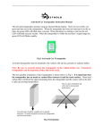
The Westhold RMS is a sophisticated multi-component system used for the timing, scoring and
management of motor sports racing events. The RMS consists of electronic hardware and PC
based MS-Windows® software. A basic hardware setup includes a computer, IDEC decoder,
Loop Antenna, and transmitters (also know as transponders). See fig. 1.1
Outside of scoring building
- Track-side
Inside scoring building
RS-232 or
Ethernet
Coax
IDEC
Balun
Loop Antenna
(E.g. Located at Start/Finish)
Computer
Fig 1.1 - Basic RMS Configuration
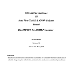
Each transmitter transmits a unique identification number. When a transmitter crosses a Loop
Antenna, the IDEC reads this number and determines the crossing time of the transmitter. The
IDEC compiles all of the information and sends it to the computer over a serial or Ethernet link
for final analysis and storage. Data can then be sent from the computer to other devices such as
scoreboards, printers, wireless hand-held lap time viewers and other third party devices.
IDEC is a receiver system that processes the raw signals picked up by the Loop Antenna. Its job
is to convert the raw signals into digital information that can then be transmitted via a RS-232
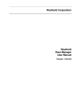
serial link or a network link to the PC. A dual port IDEC can cover two timing points such as
start/finish and pits. Multiple IDECs may be attached to a network to cover multiple timing
points for information such as split times (see fig. 1.2), pit row activity or freeze-the-field
information. This requires a GPS to synchronize all the IDECs to a common time.
Each IDEC stores what are known as hit records. Hit records describe the crossing of
transmitters over the Loop Antennas. Each record consists of a transmitter identification
number, the crossing time as well as a few other pieces of information such as transmitter battery
status. The IDEC is capable of storing hit records in its internal memory for future reference and
redundancy and is capable of determining a crossing time with spatial accuracy typically
between 2-3 inches or better. Under normal operation, the PC would upload this data and
process it as the transmitters cross the Loop Antennas. However, in the event of a computer
failure the IDEC could still save hit records for later retrieval.
3
Loop Antenna
(Timing point 1)
Loop Antenna
(Timing point 2)
balun
balun
Coax cable
IDEC
Coax cable
IDEC
(Cat 5 network Cable)
Hub/Router
Fig 1.2 Multiple Timing Point Configuration
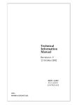
A Loop Antenna is simply insulated electrical wire with a terminating resistor on the side of the
loop furthest from the connection to the Decoder. They are buried beneath the surface of the
track and are 24 inches (approx. 60 cm) wide and can be of varying length to cover the width of
the track. See fig 1.4. A track width greater than 100 ft. (approx. 30m) can be covered with a
single Loop Antenna, but it depends on the track type (dirt versus paved), burial depth of the
loop, and the track environment (iron content in the soil or RF interference). It is not desirable to
make the Loop Antenna any longer than necessary since it will reduce the performance of the
system.
The ends of the Loop Antenna connect to the balun. The balun is a device that connects the
Loop Antenna to a RG58 (50 ohm) coax cable. The balun device matches the impedance
between the Loop Antenna section and the coax. It is necessary to have a balun device for
optimal performance. Without it the impedance mismatches can result in reduced detection
height and possibly intermittent and unpredictable behavior.
Terminating Resistor
24”
Can be greater than 100 feet (30m)
balun
Fig. 1.3 - Loop Antenna Dimensions
4
2. Installation and Usage
2.0 General Notes
The first step in an installation is to carefully plan where each piece of the system will reside.
The plan must take into account the limitations of the system. Some of these limitations are
fixed. Others are variable and dependent upon the track environment.
2.1 Antenna Installation
There are two methods for setting up the antenna; the single loop and multi-loop methods. See
the figures 2.1.1 and 2.1.2 below for the single and two loop setups. All loops should be about
24 inches wide with the resistor centered at the end of the loops. For multi-loop antennas each
loop should overlap the adjacent loop by at least the burial depth of the loop. For example if the
loop is buried at 18 inches then the overlap should be at least 18 inches. For depths less than 1
foot the minimum overlap should be 1 foot.
Terminating Resistor
24”
Can be greater than 100+ feet (30m)
Balun
Coax (To IDEC)
Fig 2.1.1 Single loop
Balun
5
Loop 1 – Terminating
Resistor
Slightly
overlapped
antenna loops
24 inches
Loop 2 - Terminating
Resistor
Overlap of 2-3 feet
Coax from
balun
Loop 1 - Balun
Loop 2 - Balun
IDEC
Serial or Network Cable
or both
Fig 2.1.2 – Multi-loop
Antenna loops are simply insulated copper electrical wire with a resistor soldered to the end of
the loop. If you prefer to make loops yourself or have a special need, the wire can be purchased
at most hardware stores while the resistor (470 ohm optimal) is available at many electronic
stores.
Note: The instructions below are only to make the detection loop. For activation loops do
not follow the instructions below. They will result in a non-operational activation loop.
The wire may be stranded or solid core. A typical gauge of wire used is AWG 20. Smaller or
larger gauges may be used. There are certain trade-offs to using smaller or larger gauges. For
example, a smaller gauge is generally less durable, but is often more flexible and easier to
manipulate.
Recommended:
Wire Type: Stranded core.
Resistor: Use approximately 470 ohms. Some deviation from this number is ok. Using a 390
ohm or 490 ohm resistor will not significantly affect the performance.
6
Heat shrink tubing: We suggest using heat shrink to encase the resistor and any exposed wire.
This will keep moisture from seeping into the wire and eating away the copper.
To install the antenna loop, cut a groove approximately ¼ inch (6-8 mm) wide and ½ inch (12-13
mm) deep in the track with the dimensions show below. See fig. 2.1.1. Depending on the wire
gauge the groove dimensions should be adjusted accordingly. For dirt tracks, place the antenna
loops in plastic PVC sprinkler pipes. Make sure the pipes are sealed such that water will not
enter the pipes.
There is no fixed depth to bury the antenna for dirt tracks. This is variable depending on the
track. Environmental factors such as metal content in the soil can reduce detection distance and
therefore the antenna cannot be buried as deeply as soil without metal content. The general rule
of thumb is to bury the antenna only as deep as necessary to keep the antenna from being
damaged, yet maintaining maximum detection distance between the antenna and the transmitter
on the vehicle. Generally keeping the antenna burial depth to less than 18 inches is
recommended. This typically is deep enough so cars and graders do not harm the antenna, but
still maintaining good detection distance.
Connect the ends of the Loop Antenna to the balun device. There are two screw terminals on the
device for the antenna wire. A BNC connector is on the opposite end of the balun. Connect the
coax cable to the BNC connector. The other end of the coax cable will then connect to the BNC
connector on the back of the Decoder.
2.2 IDEC Decoder System
A single or multi-port IDEC setup can be used. For multiple timing points the IDEC has the
capability to synchronize to a GPS time with a GPS receiver. The IDEC will either have 1 or 2
inputs for antenna. For a 2 port system the loops may be used in various configurations:
start/finish and pit, overlapping loops, split time, or separate start and finish.
Antenna cable inputs
Network Interface
DAISY
RS-232 Serial
Interface
Fig. 2.2.1 IDEC Rear Panel (1 Port System)
7
The IDEC has 3 front panel LED indicators to indicate power, communications activity with a
PC and transmitter crossings. The PWR (power) indicator will light green if the DC power
supply is high enough to properly operate the system. The IDEC uses a 6 volt DC power supply.
If the voltage is too low the LED will light red.
The communication (COM) indicator lights a solid green when it is first power on and will stay a
solid green until there is communications with a PC either through the serial or Ethernet
interface. When there is communications the COM indicator will blink.
The detection (DET) light will flash green whenever a valid transmitter has crossed the loop. It
will stay on solid green if a transmitter is sitting over the loop and does not move out of detection
range to indicate a real crossing.
Fig. 2.2.2 IDEC Front Panel
The IDEC comes with a 6 volt DC power supply. First, plug in the communication cable that
will be used whether it is the RS-232 serial cable or a network cable. If the IDEC is connected to
a hub, switch, or router, use a standard CAT-5 network cable. If the IDEC is connected directly
to the computer via the network interface you must use a CAT-5 crossover network cable. If a
network cable is used it should be plugged into a hub or router device. The IDEC comes
configured with a static IP address, 192.168.1.49. However, it can be setup to obtain an IP
address automatically via the web configuration interface. Make sure the PC is on the same
domain as the IDEC (i.e. 192.168.1.X) or you will be unable to connect via network to the IDEC.
To access the web interface, use the following username and password (cap sensitive).
Username: admin
Password: PASS
Note: Both communication interfaces may be used simultaneously. This allows for a second PC
to be connected as a backup system.
After plugging in the communication cable, plug in the coax cable(s) from the antenna loops.
Once this is done connect the 6 VDC power supply. You will see the PWR indicator and COM
indicator light up. Follow the software instructions to connect with the IDEC.
8
2.3 Transmitters/Transponders
Transmitters are often called transponders. Technically, most transmitters are not transponders.
Transponder is short for transmitter-responder. In the case of timing systems, a transponder is a
transmitter that transmits when it receives an activation signal. There are 3 types of transmitters:
rechargeable, hard-wire, and activated. All transmitters have a unique identification number that
is printed on the outside of the transmitter case. When the transmitter crosses an antenna loop
the ID is received by the IDEC and sent to the scoring software.
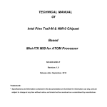
Rechargeable Transmitter
The rechargeable transmitter operates using an internal non-removable battery. There are two
LEDs, one green and one red on the transmitters. When the transmitters are fully charged and
operational they will operate for 7 days. The green LED will blink rapidly every 3 seconds. The
number of rapid blinks indicates the number of days of charge left before the transmitter will
shut off. When the transmitter is on the last day, it will begin to blink the red LED once ever 3
seconds. When this happens the timing software will receive a low battery signal from the
transmitter.
Fig 2.3.1 Rechargeable Transmitter
Rechargeable transmitters are mounted on vehicles using one of two types of holders. One type
of holder is a plastic holder with two wings for bolting to a vehicle. The other type is a nylon
fabric pouch variety with wings for bolting to a vehicle.
Note: Be sure to securely fasten the transmitter to the vehicle before use. Unsecured
transmitters can be hazardous if they fall on the track.
9
Hard-wire Transmitter
The hard-wire transmitter uses a vehicles 12 volt DC power source. It has an operational voltage
approximately between 8.5-25 VDC (older models have a max of 16VDC). If the voltage is high
enough for the unit to operate properly it will flash the green LED light. If the red LED indicator
lights up or no LED lights turn on at all the voltage level or current supplied is not enough.
Fig. 2.3.2 Hard-wire Transmitter
When connecting the leads from the hard-wire to the vehicle power source a fuse should be used
in series to protect the transmitter. The hard-wire draws less than 30 milliamps. Even though
this current draw is low, the transmitter should be hooked in such a way that it is turned off when
the vehicle is not running to prevent the battery from being drained.
The best possible orientation of the rechargeable and hard-wire transmitters is shown below with
the label side of the transmitter facing the ground Fig 2.3.3. It is important that the transmitter
has no metal or carbon fiber between it and the track surface. Metal and carbon fiber will
block the signal emanating from the transmitter and the IDEC will not be able to pick up
crossing transmitters.
Direction of Travel
Fig 2.3.3
10
Activated Transmitter/Transponder
The activated transmitter only turns on when it detects an activation signal from the Westhold
activator and activation loop. When the unit is on, a green LED indicator will flash every 3
seconds. It will blink the approximate number of hours of life remaining. Each blink signifies
100 hours. If the red LED light flashes it means the battery is on its last 100 hours.
Fig 2.3.4 Activated Transmitter
The activated transmitter is small enough to be strapped to a motocross boot or a motorcycle
fork. Unlike the other two units, the label for this transponder type should be vertical. See Fig
2.3.5 for correcting mounting position.
Direction of Travel
Fig 2.3.5
Refer to the instructions for each individual transmitter type for more detailed information.
11
3. Specifications
The RMS is capable of detecting transmitter crossings over the middle of a Loop Antenna with a
spatial accuracy of typically 2-3 inches or less and a resolution of better than one ten-thousandths
of a second. For a transmitter traveling at 200 miles per hour, that translates into sub-millisecond
accuracy.
Midline of loop
Direction of
travel
Fig 3.1.1 Direction of travel
System Specifications:
Specification
# Transmitter Ids
Max Speed
> 1,000,000
Transmitter dependent
Up to 300+ mph
100+ feet
(Depends on track type and environment)
2-3 inches typical
better than 0.0001 sec
Vehicle and track and transmitter dependent
(24-48 inches typical)
Track Width
Spatial Accuracy
Timing Resolution
Max Transmitter Height
Component Specifications:
IDEC
Dimensions
Interface to PC
Power Supply
Multiple IDECs
Internal Clock Stability
External Clock Source
Coax from Loop Antenna to IDEC
Memory
6” x 5” x 2”(15 x 13 x 2.5 cm)
RS232 or Ethernet
6VDC, 1A, Center Positive
Yes
Up to 0.5 ppm
GPS Capable
Up to 1000 feet (300m) depending on conditions
FLASH - 64,000 crossings
12
TXLI Model
Approx. 3” x 2" x 1"
(7.6 x 5.1 x 2.5cm)
Approx. 4.9oz (125grams)
32-122F (0-50C)
7 Days on full charge
LED
LED
90% Relative
Transmitter - Rechargeable
Dimensions
Weight
Temp Range
Battery Life
Operational Indicator
Low Battery Indicator
Humidity
TXDP Model
Approx. 3” x 2" x 1"
(7.6 x 5.1 x 2.5cm)
Approx. 4.3oz (122grams)
32-122F (0-50C)
+14 V > voltage > +9 V
< 30 milliamps
LEDs
90% Relative
Transmitter - Hardwire
Dimensions
Weight
Temp Range
Voltage
Current
Operational Indicator
Humidity
TXACT Model
Approx. 2.5” x 2" x 0.7"
(6.2 x 5.4 x 2cm)
Approx. 2.6oz (75grams)
32-122F (0-50C)
Depends on usage
Normal use is about 2-3 years
LEDs
90% Relative
Transmitter - Activated
Dimensions
Weight
Temp Range
Battery Life
Operational Indicator
Humidity
13
4. FCC Notices
RMS IDEC FCC Declarations:
FEDERAL COMMUNICATIONS COMMISSION RADIO AND TELEVISION INTERFERENCE
STATEMENT FOR A CLASS 'B' DEVICE
This equipment has been tested and found to comply with the limits for a Class B digital device, pursuant to
Part 15 of the FCC Rules. These limits are designed to provide reasonable protection against harmful
interference in a residential installation. This equipment generates, uses and can radiate radio frequency
energy and, if not installed and used in accordance with the instructions, may cause harmful interference to
radio communications. However, there is no guarantee that interference will not occur in a particular
installation. If this equipment does cause interference to radio or television reception, which can be
determined by turning the equipment off and then on, the user is encouraged to try to correct the interference
by one of more of the following measures:
Reorient or relocate the receiving antenna.
Increase the separation between the equipment and receiver
Connect the equipment into a different outlet so that the equipment and receiver are on different branch
circuits.
Consult the dealer or an experienced radio/TV technician for help.
This device complies with Part 15, of the FCC Rules. Operation is subject to the following two conditions: (1)
this device may not cause harmful interference, and (2) this device must accept any interference received
including interference that may cause undesired operation.
Changes or modifications not expressly approved by Westhold Corporation could void the user's authority to
operate the equipment.
TXLI RMS Rechargeable Transmitter FCC Declaration:
FEDERAL COMMUNICATIONS COMMISSION RADIO AND TELEVISION
INTERFERENCE STATEMENT
Changes or modifications not expressly approved by Westhold Corporation could void the user's
authority to operate the equipment.
This device complies with Part 15 of the FCC Rules. Operation is subject to the following two
conditions: (1) this device may not cause harmful interference, and (2) this device must accept any
interference received including interference that may cause undesired operation.
FCC ID: NKBTXLI-01, NKBTXLI-02,
IC: 677A-TXLI02
14
TXDP RMS Hardwire Transmitter FCC Declaration:
FEDERAL COMMUNICATIONS COMMISSION RADIO AND TELEVISION
INTERFERENCE STATEMENT
Changes or modifications not expressly approved by Westhold Corporation could void the user's
authority to operate the equipment.
This device complies with Part 15 of the FCC Rules. Operation is subject to the following two
conditions: (1) this device may not cause harmful interference, and (2) this device must accept any
interference received including interference that may cause undesired operation.
FCC ID: NKBTXDP-01
IC ID: 677A-TXDP01
15