1
Integration of Mat-lab Tools for DSP Code
Generation
USER MANUAL
Copyright 2005-2006 Bradley University, All rights
Reserved.
1
Table of Contents
Page
Getting Started………………………………………………………………………………………………3
1. Board Details………………………………………………………………………………………3
Getting Started with the Board………………………………………………………4
1. Embedded Target for TI C6000 DSP……………………………………4
2. Testing DSP applications…………………………………………………………5
a. Testing C6713 using external signals…………………6
b. Creating workspaces using workspace
variables……………………………………………………………………………………6-11
3. Creating an FIR filter…………………………………………………….11-14
4 Using the board to do modulation schemes –(Pending)
2
Getting Started
This user manual will provide you with a thorough
assistance in solving problems using Matlab Tools on the
Texas Instrument DSP board (TMSC6713). Problems implemented
on this board for this project, relate to the fields of
Communications and Digital Signal Processing. The Idea
behind the creation of this manual is as follows:
1. Outline common pitfalls new DSP user’s encounter and how
to avoid these pitfalls.
2. Illustrate how to build Simulink models using Matlab
Tools and how to interface and implement models on the DSP
board.
3. Show how problems can first be hard coded in C/C++,
interfaced with Matlab Tools.
DSP Board Details:
1. TMS320C6713 DSP - 225 MHz, floating point, 256 Kb internal
RAM/Cache
2. CPLD - Programmable "glue" logic
3. External SDRAM – 16 Megabytes, 32-bit Interface
4. External Flash - 512Kbytes, 8-bit interface (256Kb usable)
5. AIC23 - Stereo, 8 KHz –96KHz sample rate, 16 to 32 bit
samples, jacks, microphone, line-in, line-out and speaker
6. 4 User LEDS - Writable through CPLD
7. 4 User DIP Switches – Readable through CPLD
8. 3 Configuration Switches – Selects Power, Configuration and
boot modes
9. Daughter card Expansion Interface- allows user to enhance
functionality with add-on daughter card.
3
Getting Started with the Board
Embedded Target for TI C6000 DSP
The Embedded Target for TI C6000 DSP platform integrates
Simulink and Matlab with Texas Instrument eXpressDSP(tm)
tools. The software suite allows a user to develop DSP
designs from concept through code and automates rapid
prototyping on the C6713 DSP starter kit. The Build process
builds a Code Composer Studio (CCS) project from the C code
generated by Real-Time Workshop. The CCS project is
automatically compiled and linked, and the executable is
loaded onto your board, and run on the C6713 DSP.
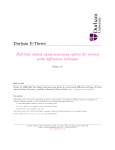
Inside of a Matlab command window type:
>> Simulink
To open the Simulink Browser that looks like this:
4
A new Simulink model is created by first clicking on the
Simulink browser as:
File>>New>>Model
1. For any model in this targeting environment, a user
must select in the above window the discrete-time
solver as:
Simulation>>Simulation Parameters>>Solver>>Solver
Options>>Fixed Step discrete (no continuous states)
2. The embedded target board for this project is the
C6713. It is selected as follows:
>> c6000tgtpreflib>>C6713 DSK
3. The C6713 board must be selected and dragged to the
new Simulink Model.
5
Testing and driving a DSP application on the C6713
The ADC and DAC blocks in the Library: C6713 dsklib above
provide physical pathways from and to external sources and
displays. They are different from sources and sinks in that
they exchange data with external devices through analog
input and output connectors. The ADC and DAC blocks are
selected as follows in the Matlab workspace:
>>c6000lib>>C6713 DSK
The ADC and DAC blocks must be selected and dragged into
the Simulink model shown below:
6
Testing the DSP board with the Function generator
1. Having designed the model on page 6, a 35mm audio jack
was connected from the Line out connector on the DSP
board to the scope. A test signal was connected from
the signal generator to the Line in connector on the
board. The DSP board is powered to a 5 volt power
supply and connected to our Host PC through the USB
port.
2. Our model is converted to C code by clicking on:
Simulation>>Simulation Parameters>>Real-Time
workshop>>generate code
A DSP/BOIS configuration file is created; a project in
CCS is created. This project in CCS is built, A COFF file
is downloaded on the DSP board and a final executable
file on the DSP board and the scope was observed.
Creating models using input workspaces/files
1. A simple sine wave was created and stored in a workspace
variable called simin as in an M-file:
npts=2000; % these are the total number of pts per cycle in our
simulation
n=0:1:npts-1; % number of pts n are in the increments of
n=0,1,2,3...1999
fss=8000; % this is the sampling frequency for the input
delta=1/fss; % this will be used in simulation purposes
t=n*delt; % Total time t=1999/8000=0.249
figure(1),
Vin=sin(2*pi*2000*t); % this is the analog signal
plot(t,Vin),grid on % this plots Vin for the specified t range
xlabel('time(seconds)');
% add axis labels and plot
title
ylabel('magnitude of sine wave');
title('A simple sine wave of freq=2000Hz');
whos; %display the contents of all variables used in matlab
workspace
7
simin=[t' Vin'] % the transpose of t and Vin is saved in the
variable simin
save myinput.mat % the values of t and Vin is saved in the
variable in an
% input file.
2. Having done this a new model was created to transfer
data from Matlab to Simulink as:
In the Simulink browser select and drag to the Simulink
model,
Simulink>>Sources>>From Workspace block>>
Click on the From Workspace block and specify under data
simin and 1/8000 as sampling time
3. A simple low-pass filter whose cut-off frequency was
714 Hz was designed with the following Transfer
Function:
H(s) = 714/(s+714)
In the Simulink browser select and drag to the Simulink
model,
Sources>>Continuous>> Transfer Fuc block
Click on the Transfer Fuc block and specify the filter in
the form of a matrix:
Num= [714]
Den= [1 714]
And the absolute tolerance in this same window is
specified as auto.
5. Having completed the filter specifications a workspace
variable will be selected to store the output from the
filter.
Simulink>>Sources>>To Workspace block>>
Click on the To Workspace block and specify under data
simout and 1/8000 as sampling time.
6. This model is simulated for 0.25 sec, which is
specified in the simulation parameter stop time window.
8
The model can now be simulated and analyzed using the
scope block found at:
Simulink>>Sinks>>Scope
7. The c6713DSK was dragged to this model and the Realtime Workshop was used start the implementation of our
model on the DSP board.
The build up process was interrupted by an error message
that only asked for discrete (no continuous-state) blocks
to be in the model. The filter whose transfer function
was specified as an H(s) had to be converted to an H(z)
using bilinear Transformation.
H(z)=H(s)|
|s=2*fss*(z-1/z+1),
Hence H(z) = (714z+714)
-------------(16714z-15286)
This discrete transfer function replaces the previous
transfer function by choosing:
>>Simulink>>Discrete>>Transfer Func Block
and specifying these parameters:
Num= [714 714]
Den= [16714 -15286]
Sampling time can be specified as -1 to inherit the
sampling frequency used in the M-file code or that
specified in simin block.
Having completed this, a Simulink model was created as
shown below:
9
This model is compiled and built using the Real-Time
Workshop and the output of the scope is observed for the
time duration of the simulation as:
This scope plot was obtained for only the time duration
of the sine wave simulation.
A much better approach would have been to design a model
that runs for an infinite amount of time using the block
in the Simulink Browser window as follows:
>> Fixed-Point Blockset>>Sources>>Repeating sequence
Stair
Upon clicking on the Repeating sequence stair block, the
vector or output variables must be specified as [Vin’]
and sampling time must be -1 to inherit the sampling
frequency of fss=1/8000. Specifying the output variable
as Vin’ will store the values of our sine wave in a loop
in this block, which can be effectively simulated for an
infinite amount of time on the DSP board.
10
This model is compiled and built using the Real-Time
Workshop and the output of the scope is observed for an
infinite amount of time shown below in the scope plot
below:
Creating an FIR filter
NOTCH Filter
Filter that passes most frequencies unaltered,
but attenuates those in a narrow range to very
low levels
Given Equation:
H(Z)=h0+h1z-1 + h2z-2
2 poles at origin which corresponds to Z2
2 zeros 45 degrees from the origin
11
From DSP class one can get the coefficients from equation
(1). That’s is [1 -1.41241 1]
This gives us our transfer function with
Numerator:
[1 -1.41241 1]
Denominator:
[1 0 0]
Following the same steps above to build a filter explained
on page 8.
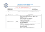
A block diagram consisting of your ADC and DAC blocks is
built in your work space as shown in the figure below.
Block diagram for creating FIR filter
12
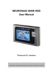
Experimental results
The scope output implies the following:
With the known coefficient I had to choose a
sampling frequency (fs) and an Analog frequency
(fd) to match the Digital frequency
fa=fd*fs
fd=Digital Frequency
fa=Analog frequency
fs=Sampling frequency
Choosing fs= 8000Hz
fd=1/8 ( Ranging between -.5 to .5)
fa= 1000Hz
This means when you turn your function generator to
a 1000Hz the filter goes to zero. Thus the straight
line on the scope output.
13
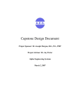
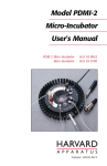
This can be proven theoretically in mat-lab using
M-file to get the desired code shown below.
Mat-lab code to generate filter
frequency response
3.5
3
2.5
2
1.5
1
0.5
0
0
500
1000
1500
2000
2500
3000
3500
4000
Plot of FIR filter fa at 1000Hz
The plot above got from the M-file code shows that
at 1000Hz the filter goes to zero.
14