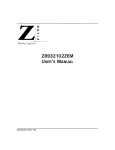
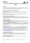
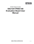
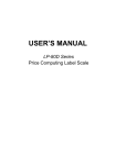
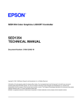
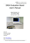
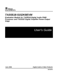
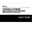
1
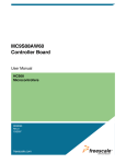
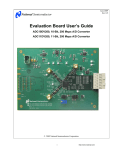
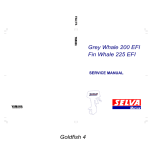
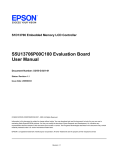
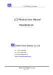
S1D13700 Embedded Memory Graphics LCD Controller
S5U13700B00C Rev. 1.0 Evaluation
Board User Manual
Document Number: X42A-G-002-01
Status: Revision 1.0
Issue Date: 2005/07/15
© SEIKO EPSON CORPORATION 2005. All Rights Reserved.
Information in this document is subject to change without notice. You may download and use this document, but only for your own use in
evaluating Seiko Epson/EPSON products. You may not modify the document. Epson Research and Development, Inc. disclaims any
representation that the contents of this document are accurate or current. The Programs/Technologies described in this document may contain
material protected under U.S. and/or International Patent laws.
EPSON is a registered trademark of Seiko Epson Corporation. All other trademarks are the property of their respective owners.
Revision 1.0
Page 2
Epson Research and Development
Vancouver Design Center
S1D13700
X42A-G-002-01
S5U13700B00C Rev. 1.0 Evaluation Board User Manual
Issue Date: 2005/07/15
Revision 1.0
Epson Research and Development
Vancouver Design Center
Page 3
Table of Contents
1
Introduction . . . . . . . . . . . . . . . . . . . . . . . . . . . . . . . . . . . . . . . . 5
2
Features . . . . . . . . . . . . . . . . . . . . . . . . . . . . . . . . . . . . . . . . . . 6
3
Installation and Configuration . . . . . . . . . . . . . . . . . . . . . . . . . . . . . . 7
3.1 Configuration DIP Switches . . . . . . . . . . . . . . . . . . . . . . . . . . 7
3.2 Configuration Jumpers . . . . . . . . . . . . . . . . . . . . . . . . . . . . 9
4
Tech nical Description . . . . . . . . . . . . . . .
4.1 Host interface . . . . . . . . . . . . . . .
4.1.1 Epson PC Card Extender Support . . . . . . .
4.1.2 Host Bus Interface Support . . . . . . . . . .
4.2 LCD Panel Interface . . . . . . . . . . . . .
4.3 Clock . . . . . . . . . . . . . . . . . . .
5
Parts List . . . . . . . . . . . . . . . . . . . . . . . . . . . . . . . . . . . . . . . . 21
6
Schematic Diagrams . . . . . . . . . . . . . . . . . . . . . . . . . . . . . . . . . . 23
7
S5U13700B00C Board Layout . . . . . . . . . . . . . . . . . . . . . . . . . . . . . 26
8
Connecting the S5U13700B00C to the PC Card Adapter
9
References . . . . . . . . . . . . . . . . . . . . . . . . . . . . . . . . . . . . . . . 29
9.1 Documents . . . . . . . . . . . . . . . . . . . . . . . . . . . . . . . 29
9.2 Document Sources . . . . . . . . . . . . . . . . . . . . . . . . . . . . 29
. . . .
. . .
. . . .
. . . .
. . .
. . .
. . . . . .
. . . . .
. . . . . . .
. . . . . . .
. . . . .
. . . . .
.
.
.
.
.
.
. . . . . . .
. . . . . .
. . . . . . . .
. . . . . . . .
. . . . . .
. . . . . .
18
18
18
18
20
20
. . . . . . . . . . . . . . 28
10 Technical Support . . . . . . . . . . . . . . . . . . . . . . . . . . . . . . . . . . . 30
10.1 EPSON Mobile Graphics Engines (S1D13700) . . . . . . . . . . . . . . . . . 30
10.2 Ordering Information . . . . . . . . . . . . . . . . . . . . . . . . . . . 30
Appendix A Epson PC Card Extender . . . . . . .
A.1 Features . . . . . . . . . . . . . . . .
A.2 General . . . . . . . . . . . . . . . .
A.3 Power . . . . . . . . . . . . . . . .
A.4 Bus Disable . . . . . . . . . . . . . .
A.5 16-Bit PC Card Mode . . . . . . . . . .
A.6 Generic #1 / #2 Bus . . . . . . . . . . .
A.7 Epson Evaluation Boards . . . . . . . . .
A.8 Epson Evaluation Board Header Pin Mapping .
S5U13700B00C Rev. 1.0 Evaluation Board User Manual
Issue Date: 2005/07/15
.
.
.
.
.
.
.
.
.
.
.
.
.
.
.
.
.
.
. . .
. .
. .
. .
. .
. .
. .
. .
. .
.
.
.
.
.
.
.
.
.
.
.
.
.
.
.
.
.
.
.
.
.
.
.
.
.
.
.
. . .
. .
. .
. .
. .
. .
. .
. .
. .
.
.
.
.
.
.
.
.
.
.
.
.
.
.
.
.
.
.
.
.
.
.
.
.
.
.
.
. . .
. .
. .
. .
. .
. .
. .
. .
. .
.
.
.
.
.
.
.
.
.
.
.
.
.
.
.
.
.
.
.
.
.
.
.
.
.
.
.
31
31
31
31
32
32
32
32
32
S1D13700
X42A-G-002-01
Revision 1.0
Page 4
Epson Research and Development
Vancouver Design Center
S1D13700
X42A-G-002-01
S5U13700B00C Rev. 1.0 Evaluation Board User Manual
Issue Date: 2005/07/15
Revision 1.0
Epson Research and Development
Vancouver Design Center
Page 5
1 Introduction
This manual describes the setup and operation of the S5U13700B00C Rev. 1.0 Evaluation
Board. This evaluation board is designed as an evaluation platform for the S1D13700
Embedded Memory Graphics LCD Controller.
The S5U13700B00C is designed for connection to the Epson PC Card Extender
(S5UPCMCIAB00C), thus providing an easy connection to a laptop or a desktop computer
with a PC Card reader. This module can also be used with other native platforms via the
host connectors which provide the appropriate signals to support a variety of CPUs.
This user manual is updated as appropriate. Please check the Epson Research and Development Website at www.erd.epson.com for the latest revision of this document before
beginning any development.
We appreciate your comments on our documentation. Please contact us via email at
[email protected].
S5U13700B00C Rev. 1.0 Evaluation Board User Manual
Issue Date: 2005/07/15
S1D13700
X42A-G-002-01
Revision 1.0
Page 6
Epson Research and Development
Vancouver Design Center
2 Features
The S5U13700B00C Rev. 1.0 evaluation board includes the following features:
• 64-pin TQFP13 S1D13700F0x Embedded Memory Graphics LCD Controller
• Headers for connecting to various Host Bus Interfaces or to the Epson PC Card
Extender
• 0.1x0.1” header with all the LCD interface signals allowing connection to a LCD panel
• On-board 32MHz crystal and option to use an oscillator instead of the crystal
• On-board +3.3V regulator
S1D13700
X42A-G-002-01
S5U13700B00C Rev. 1.0 Evaluation Board User Manual
Issue Date: 2005/07/15
Revision 1.0
Epson Research and Development
Vancouver Design Center
Page 7
3 Installation and Configuration
The S5U13700B00C evaluation board incorporates a DIP switch and 9 jumpers, which
allow configuration of the board.
3.1 Configuration DIP Switches
An 8 position DIP switch (S1) is used to configure the S1D13700 for different Host Bus
interfaces and to select the FPSHIFT cycle time. The following figure shows the location
of DIP switch S1 on the S5U13700B00C.
DIP Switch - S1
Top View
Figure 3-1: Configuration DIP Switch (S1) Location
S5U13700B00C Rev. 1.0 Evaluation Board User Manual
Issue Date: 2005/07/15
S1D13700
X42A-G-002-01
Revision 1.0
Page 8
Epson Research and Development
Vancouver Design Center
All S1D13700 configuration inputs (CNF[4:0]) are fully configurable using DIP switch S1
as described below.
Table 3-1: Summary of Configuration Options
SDU13700B00C
S1-[8:1]
Configuration
S1D13700
Pin
S1-[8:7]
-
S1-[6]
AS#
S1-[5]
CNF4
S1-[4:3]
CNF[3:2]
Configuration State
1 (ON)
0 (OFF)
Not used
Generic Bus or M6800 Family Bus Interface
M68K Family Bus Interface
Indirect Addressing Mode
Direct Addressing Mode
Selects the host bus interface as follows:
CNF3
CNF2
Host Bus
0
0
Generic Bus
0
1
Reserved
1
0
M6800 Family Bus Interface
1
1
MC68K Family Bus Interface
Selects the FPSHIFT cycle time (FPSHIFT:Clock Input) as follows:
CNF1
CNF0
FPSHIFT Cycle Time
S1-[2:1]
CNF[1:0]
0
0
FPSHIFT Divide 4:1
0
1
FPSHIFT Divide 8:1
1
0
FPSHIFT Divide 16:1
1
1
Reserved
= Required settings when using the PC Card adapter
S1D13700
X42A-G-002-01
S5U13700B00C Rev. 1.0 Evaluation Board User Manual
Issue Date: 2005/07/15
Revision 1.0
Epson Research and Development
Vancouver Design Center
Page 9
3.2 Configuration Jumpers
The S5U13700B00C has 9 jumper blocks which allow the configuration of the board.
Table 3-2: Jumper Summary
Jumper
Function
Position 1-2
Position 2-3
JP1
HIOVDD
Normal
—
JP2
NIOVDD
Normal
—
JP3
COREVDD
Normal
—
JP4
CLKI Source
JP5
CLKI Input Disable
JP6
JP7
JP8
JP9
Crystal Enable
HIOVDD Voltage
NIOVDD Voltage
RESET Source
On Board Oscillator (U2)
Disable CLKI Input
(CLKI is tied to VSS)
Enable Crystal Output
+3.3V
+3.3V
Manual Reset
Host Interface Connector
Disable Crystal Input
(XCG1 is tied to VSS)
Disable Crystal Output
+5V
+5V
Host Interface Reset
No Jumper
HIOVDD current
measurement
NIOVDD current
measurement
COREVDD current
measurement
—
—
—
—
—
—
= Required settings when using the PC Card adapter
S5U13700B00C Rev. 1.0 Evaluation Board User Manual
Issue Date: 2005/07/15
S1D13700
X42A-G-002-01
Revision 1.0
Page 10
Epson Research and Development
Vancouver Design Center
JP1 - HIOVDD
JP1 can be used to measure the current consumption of the S1D13700 host interface.
When the jumper is at position 1-2, normal operation is selected.
When no jumper is installed, host interface current consumption can be measured across
JP1.
Note
The HIOVDD voltage can be selected to be +3.3V or +5V using jumper JP7.
JP1
Normal Operation
HIOVDD current
measurement
Top View
Figure 3-2: Configuration Jumper JP1 Location
S1D13700
X42A-G-002-01
S5U13700B00C Rev. 1.0 Evaluation Board User Manual
Issue Date: 2005/07/15
Revision 1.0
Epson Research and Development
Vancouver Design Center
Page 11
JP2 - NIOVDD
JP2 can be used to measure the current consumption of the S1D13700 LCD panel interface.
When the jumper is at position 1-2, normal operation is selected.
When no jumper is installed, panel interface current consumption can be measured across
JP2.
Note
The NIOVDD voltage can be selected to be +3.3V or +5V using jumper JP8.
JP2
Normal Operation
NIOVDD current
measurement
Top View
Figure 3-3: Configuration Jumper JP2 Location
S5U13700B00C Rev. 1.0 Evaluation Board User Manual
Issue Date: 2005/07/15
S1D13700
X42A-G-002-01
Revision 1.0
Page 12
Epson Research and Development
Vancouver Design Center
JP3 - COREVDD
JP3 can be used to measure the current consumption of the S1D13700 core.
When the jumper is at position 1-2, normal operation is selected.
When no jumper is installed, core current consumption can be measured across JP3.
JP3
Normal Operation
COREVDD current
measurement
Top View
Figure 3-4: Configuration Jumper JP3 Location
S1D13700
X42A-G-002-01
S5U13700B00C Rev. 1.0 Evaluation Board User Manual
Issue Date: 2005/07/15
Revision 1.0
Epson Research and Development
Vancouver Design Center
Page 13
JP4 - CLKI Source
JP4 is used to select the clock source for the S1D13700 CLKI input.
When the jumper is at position 1-2, the clock source is the on-board oscillator (U2).
When the jumper is at position 2-3, the clock source is from the host interface connector
(connector P1, pin 4).
JP4
On-board oscillator
(U2)
Host interface
connector
Top View
Figure 3-5: Configuration Jumper JP4 Location
S5U13700B00C Rev. 1.0 Evaluation Board User Manual
Issue Date: 2005/07/15
S1D13700
X42A-G-002-01
Revision 1.0
Page 14
Epson Research and Development
Vancouver Design Center
JP5 - CLKI Input Disable
JP5 is used to disable the S1D13700 clock input that is not used by connecting it to ground.
When the jumper is at position 1-2, CLKI input is disabled.
When the jumper is at position 2-3, XCG1 input is disabled.
Note
When jumper JP5 is at position 1-2, jumper JP6 must also be at position 1-2.
When jumper JP5 is at position 2-3, jumper JP6 must also be at position 2-3.
JP5
Disable CLKI input
Disable XCG1input
Top View
Figure 3-6: Configuration Jumper JP5 Location
S1D13700
X42A-G-002-01
S5U13700B00C Rev. 1.0 Evaluation Board User Manual
Issue Date: 2005/07/15
Revision 1.0
Epson Research and Development
Vancouver Design Center
Page 15
JP6 - Crystal Enable
JP6 is used to enable or disable the S1D13700 crystal output (XCD1).
When the jumper is at position 1-2, XCD1 output is enabled by connecting it to the crystal.
When the jumper is at position 2-3, XCD1 output is disabled by disconnecting it from the
crystal.
Note
When jumper JP6 is at position 1-2, jumper JP5 must also be at position 1-2.
When jumper JP6 is at position 2-3, jumper JP5 must also be at position 2-3.
JP6
Enable XCD1 output
Disable XCD1
output
Top View
Figure 3-7: Configuration Jumper JP6 Location
S5U13700B00C Rev. 1.0 Evaluation Board User Manual
Issue Date: 2005/07/15
S1D13700
X42A-G-002-01
Revision 1.0
Page 16
Epson Research and Development
Vancouver Design Center
JP7 - HIOVDD Voltage
JP7 is used to select the voltage for HIOVDD.
When the jumper is at position 1-2, HIOVDD is +3.3V.
When the jumper is at position 2-3, HIOVDD is +5V.
JP7
+3.3V
+5V
Top View
Figure 3-8: Configuration Jumper JP7 Location
JP8 - NIOVDD Voltage
JP8 is used to select the voltage for NIOVDD.
When the jumper is at position 1-2, NIOVDD is +3.3V.
When the jumper is at position 2-3, NIOVDD is +5V.
JP8
+3.3V
+5V
Top View
Figure 3-9: Configuration Jumper JP8 Location
S1D13700
X42A-G-002-01
S5U13700B00C Rev. 1.0 Evaluation Board User Manual
Issue Date: 2005/07/15
Revision 1.0
Epson Research and Development
Vancouver Design Center
Page 17
JP9 - RESET# Source
JP9 is used to select the source of the RESET# signal to the S1D13700.
When the jumper is at position 1-2, the S1D13700 is reset by the on-board reset button
(SW1).
When the jumper is at position 2-3, the S1D13700 is reset by the system (connector P1, pin
21).
JP9
Manual reset
Host interface reset
Top View
Figure 3-10: Configuration Jumper JP9 Location
S5U13700B00C Rev. 1.0 Evaluation Board User Manual
Issue Date: 2005/07/15
S1D13700
X42A-G-002-01
Revision 1.0
Page 18
Epson Research and Development
Vancouver Design Center
4 Technical Description
4.1 Host interface
4.1.1 Epson PC Card Extender Support
The evaluation board is designed to connect to the Epson PC Card Extender
(S5UPCMCIAB00C). The extender provides an easy connection to any computer with an
available PC Card slot. The S5U13700B00C directly connects to the extender via
connectors P1 and P2 (see Section 8, “Connecting the S5U13700B00C to the PC Card
Adapter” on page 28).
Note
When using this evaluation board with the Epson PC Card Extender, the maximum current draw of 750mA provided by the PC Card slot may be exceeded. If the combination
of module and LCD panel exceeds this limit, an external 5V power supply may be required. The 5V regulated power supply may be connected to the 5V test point (TP5V1)
and the GND test point (TPGND1) to power the on-board regulator. In this case, the 0
Ohm resistor R2 must be removed from the board.
4.1.2 Host Bus Interface Support
The S1D13700 supports several host bus interfaces. All S1D13700 host interface pins are
available on connectors P1 and P2 allowing the S5U13700B00C to be used for interfacing
to other platforms.
All host interface signals must match HIOVDD of the S1D13700. The default value for
HIOVDD on the board is +3.3V, so it will work with the Epson PC Card Extender
(S5UPCMCIAB00C). HIOVDD can be selected between +3.3V and +5V using jumper
JP7.
S1D13700
X42A-G-002-01
S5U13700B00C Rev. 1.0 Evaluation Board User Manual
Issue Date: 2005/07/15
Revision 1.0
Epson Research and Development
Vancouver Design Center
Page 19
The following diagram shows the location of the host bus connectors (P1 and P2).
Connectors P1 and P2 are 2x2mm headers, 40 pins (20x2) each.
P1 and P2
CPU Bus Connectors
Bottom View
Figure 4-1: CPU Bus Connectors (P1 and P2) Location
For the pinout of connectors P1 and P2, refer to the schematics (see Section 6, “Schematic
Diagrams” on page 23).
Note
1. When the board is connected to a PC using the Epson PC Card Extender, the signal
AS# is not used and R12 must NOT be populated. AS# input of S1D13700 should
be connected to HIOVDD by setting the dip switch (S1) position 6 to ON.
2. When the board is connected to different platforms, the Epson PC Card Extender is
not used. If using MC68K Family Bus interface, the signal AS# is used and it can be
provided to the P2 connector by populating R12 and the dip switch (S1) position 6
must be set to OFF position to disconnect AS# input from HIOVDD.
S5U13700B00C Rev. 1.0 Evaluation Board User Manual
Issue Date: 2005/07/15
S1D13700
X42A-G-002-01
Revision 1.0
Page 20
Epson Research and Development
Vancouver Design Center
4.2 LCD Panel Interface
All the LCD interface signals are available on connector H1. Connector H1 is a 8x2 header,
0.1x0.1” pitch. The following diagram shows the location of the LCD connector (H1).
H1
LCD Connector
Top View
Figure 4-2: LCD Connector (H1) Location
For the pinout of connector H1, refer to the schematics (see Section 6, “Schematic
Diagrams” on page 23).
4.3 Clock
The S1D13700 accepts a clock signal from an oscillator or from a crystal. If the oscillator
is used, the crystal input (XCG1) must be connected to ground and the crystal output
(XCD1) must not be connected. If the crystal is used, the clock input (CLKI) must be
connected to ground. For details on connecting CLKI or XCG1 to ground, refer to the JP5
description (see “JP6 - Crystal Enable” on page 15).
The default configuration of the S5U13700B00C uses a 32MHz crystal. Jumper JP5 is in
position 1-2 to connect the CLKI input to ground because it is not used. Jumper JP6 is in
position 1-2 to connect the XCD1 output to the crystal.
The board can use the CLKI input instead of the crystal. To use the CLKI input, JP5 must
be moved to position 2-3 to connect the XCG1 input to ground. Also, jumper JP6 must be
moved to position 2-3 to disconnect the XCD1 output from the crystal.
The CLKI signal can be provided on the host interface connector or by an on-board oscillator. Jumper JP4 is used to select the clock source. In position 1-2, the clock is provided
by populating an oscillator into the 14-pin DIP socket U2. In position 2-3, the clock must
be provided on pin 4 of the host interface connector P1.
S1D13700
X42A-G-002-01
S5U13700B00C Rev. 1.0 Evaluation Board User Manual
Issue Date: 2005/07/15
Revision 1.0
Epson Research and Development
Vancouver Design Center
Page 21
5 Par ts List
Table 5-1: Parts List
Item
Qty
Reference
1
5
C1,C12,C13,C20,
C22
2
8
3
Part
Mfg / PN
Notes
47uF 10V
Kemet T494B476M010AS
CAPACITOR TANT 47UF 10V 20%
SMT
C2,C3,C4,C10,
C11,C14,C15,C16
0.01uF
Panasonic - ECG PCC103BQCT
16
C5,C6,C7,C8,C9,
C17,C18,C19,C21,
C23,C25,C26,C27,
C29,C32,C33
0.1uF
Yageo America
04022F104Z7B20D
4
2
C24,C28
100uF 10V T
Kemet T494D107K010AS
CAPACITOR TANT 100UF 10V 10%
SMT
5
2
C31,C30
12 pF
Panasonic - ECG ECJ1VC1H120J
CAP 12PF 50V CERAMIC 0603 SMD
6
1
D1
Power
Panasonic - SSG LNJ308G8LRA
LED GREEN SS TYPE LOW CUR
SMD
7
1
F1
MINISMDC1102, 1100mA
Raychem Corp/Polyswitch
Division MINISMDC110-2
POLYSWITCH 1.1A RESET FUSE
SMD
8
1
H1
HEADER 8X2
3M/ESD 2516-6002UB
9
3
JP1,JP2,JP3
CONN HEADER VERT 2POS .100
TIN or GENERIC
10
6
JP4,JP5,JP6,JP7,
JP8,JP9
CONN HEADER VERT 3POS .100
TIN or GENERIC
11
2
P1,P2
12
1
R1
22K
13
1
R2
0
14
1
R3
120R,0.1%
Sullins Electronics Corp.
PRPN202PAEN
CTS Corporation
742C163223JTR
RES ARRAY 16TRM 8RES SMD
Panasonic - ECG ERA-3YEB120V
Or equivalent
Panasonic - ECG ERA-3YEB200V
RES 200 OHM 0.1% SMD 0603
15
1
R4
240R
16
1
R5
200R,0.1%
17
1
R6
1M
18
1
R7
100R
19
0
R8,R9,R12
NP
20
2
R10,R11
0
21
1
R13
22k
22
9
SH1,SH2,SH3,
SH4,SH5,SH6,
SH7,SH8,SH9
.100 in. Jumper
Shunt
Sullins Electronics Corp.
STC02SYAN
JUMPER SHORTING TIN
23
1
SW1
SW TACTSPST
ITT Industries KSC241J
SWITCH TACT SILVER PLT J-TYPE
24
1
S1
CONFIG SW
C&K TDA08H0SK1
SWITCH DIP 8POS HALF PITCH
SMT
S5U13700B00C Rev. 1.0 Evaluation Board User Manual
Issue Date: 2005/07/15
S1D13700
X42A-G-002-01
Revision 1.0
Page 22
Epson Research and Development
Vancouver Design Center
Table 5-1: Parts List
Item
Qty
Reference
Part
Mfg / PN
Notes
25
3
TPGND1,TP5V1,
TPP3.3V1
TP_SMT
Keystone 5015
PC TEST POINT MINIATURE SMT
26
1
U1
S1D13700_TQ
FP13-64
27
1
U2
Oscillator
Socket
28
1
U3
LT1117CST
Linear Technology LT1117CST
IC LDO REG ADJUSTBL 800MA
SOT223
29
1
U4
SN74LVC2G17
Texas Instruments
SN74LVC2G17DBVR
IC BUFFER DUAL SHMT-TRG SOT23-6
30
1
U5
TPS3801K33D
CKR
Texas Instruments
TPS3801K33DCKR
IC 2.93V SUPPLY MON SOT-323-5
31
1
X1
Crystal32MHz_
MA306
Epson MA-306 32.0000M-C0
14 pin narrow DIP, screw machine
socket
S1D13700
X42A-G-002-01
S5U13700B00C Rev. 1.0 Evaluation Board User Manual
Issue Date: 2005/07/15
Revision 1.0
2
1
C2
C1
47uF 10V
C3
0..01uF
C4
0..01uF
0.01uF
C5
C6
0.1uF
0.1uF
C7
0.1uF
NIOVDD
Place a 0.01uF and a 0.1uF cap on each
NIOVDD power pin of the S1D13700
D
JP1
HIOVDD
0.01uF
C18
C19
0.1uF
0.1uF
0.1uF
.100 in.. Jumper Shuntt
1
2
.100 in.. Jumper Shuntt
AS#
R D#
WE#
CS#
WA IT#
A15
A14
A13
A12
A11
A10
A9
A8
A7
A6
A5
A4
A3
A2
A1
A0
62
63
64
2
3
4
5
6
8
9
10
11
13
14
15
16
A15
A14
A13
A12
A11
A10
A9
A8
A7
A6
A5
A4
A3
A2
A1
A0
D7
D6
D5
D4
D3
D2
D1
D0
44
45
46
47
49
50
51
52
D7
D6
D5
D4
D3
D2
D1
D0
AS#
61
41
42
43
54
AS#
RD#
WR#
CS#
WAIT#
36
3
RESET#
2
XCD1
2
XCG1
35
2
CLKI
39
34
FPDAT3
FPDAT2
FPDAT1
FPDAT0
18
19
20
21
FPDAT3
FPDAT2
FPDAT1
FPDAT0
H1
FPDAT0
FPDAT2
YSCL
FPFRAME
FPSHIFT
MOD
XECL
HIOVDD
FPSHIFT
YSCL
FPLINE
23
29
26
FPSHIFT
YSCL
FPLINE
XECL
FPFRAME
MOD
24
30
27
XECL
FPFRAME
MOD
31
YDIS
1
3
5
7
9
11
13
15
FPDAT1
FPDAT3
FPLINE
2
4
6
8
10
12
14
16
C
NIOVDD
YDIS
5V
HEADER 8X2
S1
CONFIG SW
YDIS
5V
NIOVDD
C21
0.1uF
C20
AS#
CNF0
CNF1
CNF2
CNF3
CNF4
56
57
58
59
60
47uF 10V
C22
C23
0.1uF
47uF 10V
CNF0
CNF1
CNF2
CNF3
CNF4
B
R1
22K
37
SCANEN
RESET#
XCD1
TSTEN
38
XCG1
CLKI
1
17
28
33
53
VSS
VSS
VSS
VSS
VSS
Revision 1.0
D[7:0]
3
3
3
3
3
47uF 10V
0..01uF
COREVDD
COREVDD
COREVDD
HIOVDD
HIOVDD
HIOVDD
NIOVDD
NIOVDD
A[15:0]
C
B
0..01uF
NIOVDD
U1
3
0.1uF
SH2
C12
JP2
JP3
COREVDD
3
0.1uF
C11
16
15
14
13
12
11
10
9
0..01uF
C17
C10
1
2
3
4
5
6
7
8
0..01uF
C16
C9
8
7
6
5
4
3
2
1
C13
47uF 10V
C15
C8
9
10
11
12
13
14
15
16
C14
2
1
SH3
Place a 0.01uF and a 0.1uF cap on each
COREVDD power pin of the S1D13700
12
25
40
7
48
55
22
32
3.3V
1
Place a 0.01uF and a 0.1uF cap on each
HIOVDD power pin of the S1D13700
.100 in.. Jumper Shuntt
D
2
Epson Research and Development
Vancouver Design Center
SH1
3
6 Schematic Diagrams
4
HIOVDD
Figure 6-1: S5U13700B00C Schematics (1 of 3)
S5U13700B00C Rev. 1.0 Evaluation Board User Manual
Issue Date: 2005/07/15
5
S1D13700_TQFP13-64
A
A
Titlle
S1D13700
Siize
B
Datte::
5
4
3
2
Documentt Number
13700B00C PC Card Modull e
Wednesday,, Apriil 06,, 2005
Rev
1.0
Sheett
1
off
3
1
Page 23
S1D13700
X42A-G-002-01
Page 24
S1D13700
X42A-G-002-01
5
4
3
2
1
1
TP5V1
TP_SMT
D
D
F1
R2
0
1
1
2
2
5V
1
5V_CON_SUPPLY
MIINIISMDC110-2,, 1100mA
C25
0.1uF
Place circuit as
close as possible
S1D13700
+ C24
100uF 10V T
to
2
HIOVDD
U2
7
VCC
NC
GND
OUT
1
8
0.1uF
TPGND1
TP_SMT
Oscillattor Sockett
1
CLKI Select
1-2_Oscillator
2-3_P1_
Connector
Voltage regulator
3.3V @ 800mA
PCB HeatSinked
CLKI
JP5
Cll ock Source
1
CLOCK SH4
U3
VOUT
VOUT
3.3V
ADJ
R3
120R,, 0..1%
C29
+ C28
100uF 10V T
3.3V
.100 in.. Jumper Shuntt
C
1
2
3
2-3_Crystal
SH5
0.1uF
2
LT1117CST
1
1
0.1uF
Input Disable
1-2_Oscillator
1
VIN
C27
2
4
2
3
1
JP4
CLKII Selectt
3
5V
C
1
2
3
TPP3.. 3V1
TP_SMT
2
R4
240R
.100 in.. Jumper Shuntt
R5
200R,,0.. 1%
XCD1
JP6
Crystall
1
Revision 1.0
D1
Power
Crystal
1-2_Enabled
2-3_Disabled
1
1
2
3
R6
1M
XCG1
SH6
X1
HIOVDD Select
1-2 3.3V
2-3 5.0V
B
.100 in.. Jumper Shuntt
1
2
SH7
C30
12 pF
JP7
1
2
3
.100 in.. Jumper Shuntt
1
R7
100R
XIN
XOUT
NC
NC
4
Clock Trace should be as short as
possible. Isolate Crystal with
ground trace
B
3
Crystall 32MHz_MA306
C31
12 pF
3.3V
HIOVDD
5V
HIO Voltage
Surround
crystal with ground island
NIOVDD Selection
1-2 3.3V
2-3 5.0V
SH8
A
.100 in.. Jumper Shuntt
JP8
A
1
2
3
3.3V
NIOVDD
5V
NIO Voltage
Titlle
Panell Connecttor
5
4
3
2
Siize
B
Documentt Number
13700B00C PC Card Modull e
Datte::
Thursday,, Apriil 07,, 2005
Rev
1..0
Sheett
1
2
off
3
Epson Research and Development
Vancouver Design Center
S5U13700B00C Rev. 1.0 Evaluation Board User Manual
Issue Date: 2005/07/15
Figure 6-2: S5U13700B00C Schematics (2 of 3)
14
C26
3
2
1
PC Card Noise Eliminator on WE# & RD#
D
R8
CON_WE#
1
1A
1Y
R10
6
NP
WE#
1
R9
NP
RD#
1
HIOVDD
VCC
0
3
CON_RD#
2A
2Y
4
R11
Epson Research and Development
Vancouver Design Center
4
D
Revision 1.0
Figure 6-3: S5U13700B00C Schematics (3 of 3)
S5U13700B00C Rev. 1.0 Evaluation Board User Manual
Issue Date: 2005/07/15
5
5
C32
0
0.1uF
GND
U4A
SN74LVC2G17
2
U4C
U4B
SN74LVC2G17
SN74LVC2G17
HIOVDD
U5
4
1
5
3
C33
1
2
0.1uF
2
C
3
VDD RESET#
MR#
GND
GND
TPS3801K33 DCKR
4
SW1
SW TACT-SPST
C
SH9
.100 i n.. Jumper Shuntt
Module
CPU Bus Connectors
5V_CON_SUPPLY
5V_CON_SUPPLY
2
CLOCK
1
WAIT#
1
2
3
4
5
6
7
8
9
10
11
12
13
14
15
16
17
18
19
20
B
CON_WE#
CON_RD#
VCC
GND
VCC
D0
D1
GND
BUSCLK
D2
D3
GND
WAIT#
D4
CE2#
D5
CE1#
D6
REG#
D7
INPACK#
GND
WP/IOIS16#
D8
D9
GND
RDY/IREQ#
D10
D11
BVD2/SPKR#
D12
BVD1/STSCHG#
WE#
D13
D14
OE#
D15
IOWR#
IORD#
GND
GND
RESET#
D[7:0]
40
39
38
37
36
35
34
33
32
31
30
29
28
27
26
25
24
23
22
21
JP9
RESET Selectt or
1
D0
D1
D2
D3
D4
D5
D6
D7
1
1
HIOVDD
AS#
CS#
R12
NP
R13
22k
RESET_BUS#
P1
HEADER MO DULE P1
P1 and P2 are the CPU bus connector.
Epson PC Card Adapter board.
Signals
on the headers
The power supply
It was intended
is pulled
GND
CS8#
CS#
M/R#
BS#
RD#
RD/WR#
WE0#
WE1#
GND
A25
A24
A23
A22
A21
A20
A19
A18
A17
GND
GND
A0
A1
A2
A3
A4
A5
A6
A7
GND
A8
A9
A10
A11
A12
A13
A14
A15
A16
GND
40
39
38
37
36
35
34
33
32
31
30
29
28
27
26
25
24
23
22
21
A[15:0]
1
2
3
RESET#
1
1
A0
A1
A2
A3
A4
A5
A6
1-2 Manual Reset
2-3 Host Interface
Reset
RESET_BUS#
A7
A8
A9
A10
A11
A12
A13
A14
A15
B
P2
HEADER MODULE P2
to be as generic
that are not used have an X besides
for the module
1
2
3
4
5
6
7
8
9
10
11
12
13
14
15
16
17
18
19
20
as possible
and also to mate with the
it.
in from P1 connector.
It should
be 5V DC regulated.
A
A
Titlle
Host Bus Connecttor
Siize
B
Datte::
5
4
3
2
Documentt Number
13700B00C PC Card Modulle
Wednesday,, Apriil 06,, 2005
Rev
1.0
Sheett
3
off
3
1
Page 25
S1D13700
X42A-G-002-01
Page 26
Epson Research and Development
Vancouver Design Center
7 S5U13700B00C Board Layout
Figure 7-1: S5U13700B00C Board Layout (Top View)
S1D13700
X42A-G-002-01
S5U13700B00C Rev. 1.0 Evaluation Board User Manual
Issue Date: 2005/07/15
Revision 1.0
Epson Research and Development
Vancouver Design Center
Page 27
Figure 7-2: S5U13700B00C Board Layout (Bottom View)
S5U13700B00C Rev. 1.0 Evaluation Board User Manual
Issue Date: 2005/07/15
S1D13700
X42A-G-002-01
Revision 1.0
Page 28
Epson Research and Development
Vancouver Design Center
8 Connecting the S5U13700B00C to the PC Card
Adapter
S5U13700B00C
Type II
PC Card
Slot
PC Card Adapter
Figure 8-1: Connecting the S5U13700B00C to the PC Card Adapter
S1D13700
X42A-G-002-01
S5U13700B00C Rev. 1.0 Evaluation Board User Manual
Issue Date: 2005/07/15
Revision 1.0
Epson Research and Development
Vancouver Design Center
Page 29
9 References
9.1 Documents
• Epson Research and Development, Inc., S1D13700F01 Hardware Functional Specification, document number X42A-A-002-xx.
9.2 Document Sources
• Epson Research and Development Website: http://www.erd.epson.com.
• PC Card Standard, March 1997.
S5U13700B00C Rev. 1.0 Evaluation Board User Manual
Issue Date: 2005/07/15
S1D13700
X42A-G-002-01
Revision 1.0
Page 30
Epson Research and Development
Vancouver Design Center
10 Technical Support
10.1 EPSON Mobile Graphics Engines (S1D13700)
Japan
Seiko Epson Corporation
IC International Sales Group
421-8, Hino, Hino-shi
Tokyo 191-8501, Japan
Tel: 042-587-5812
Fax: 042-587-5564
http://www.epson.co.jp/
Hong Kong
Epson Hong Kong Ltd.
20/F., Harbour Centre
25 Harbour Road
Wanchai, Hong Kong
Tel: 2585-4600
Fax: 2827-4346
http://www.epson.com.hk//
North America
Epson Electronics America, Inc.
150 River Oaks Parkway
San Jose, CA 95134, USA
Tel: (408) 922-0200
Fax: (408) 922-0238
http://www.eea.epson.com/
Taiwan
Epson Taiwan Technology & Trading Ltd.
14F, No. 7
Song Ren Road
Taipei 100, Taiwan, ROC
Tel: 02-8786-6688
Fax: 02-8786-6677
http://www.epson.com.tw/
Europe
Epson Europe Electronics GmbH
Riesstrasse 15
80992 Munich, Germany
Tel: 089-14005-0
Fax: 089-14005-110
http://www.epson-electronics.de/
Singapore
Epson Singapore Pte., Ltd.
No. 1
Temasek Avenue #36-00
Millenia Tower
Singapore, 039192
Tel: 337-7911
Fax: 334-2716
http://www.epson.com.sg/
10.2 Ordering Information
To order the S5U13700B00C Evaluation Board, contact the Epson sales representative in
your area and order part number S5U13700P00C000.
S1D13700
X42A-G-002-01
S5U13700B00C Rev. 1.0 Evaluation Board User Manual
Issue Date: 2005/07/15
Revision 1.0
Epson Research and Development
Vancouver Design Center
Page 31
Appendix A Epson PC Card Extender
This section describes the setup and operation of the PC Card Extender Board Rev 1.0. This
board was designed as an evaluation interface for connecting Epson S1D137xx Mobile
Graphics Engine Evaluation Boards to the PC Card Bus.
A.1 Features
The PC Card Extender Board Rev 1.0 includes the following features.
• Header Signals for connecting Epson S1D137xx Mobile Graphics Engine Evaluation
Boards
• Epson Identification EEPROM
• Current limiting, resettable fuse
• LED power indicators
• Voltage Level shifting to 3.3V
A.2 General
The PC Card Extender Board is designed to be connected to a laptop supporting a PC Card
Type II or Type III slot. The extender board includes an EEPROM containing the identification to specify it as an EPSON LCD controller. The software driver supplied by Epson
will recognize this PC Card as an Epson LCD Controller.
The power supplies from the PC Card host are passed to the evaluation board headers. A
resettable PolySwitch fuse (750mA) is placed on Vcc to protect the PC Card bus from
excessive current consumption. If necessary, the evaluation board can be connected to an
external power supply.
Note
Permanent damage to the host is possible if signals are shorted on the connector.
Care must be taken in attaching the modules.
The performance of the Mobile Graphics Engine in this environment is directly proportional to the PC Card bus speeds. The maximum data bus transfer speed is 10MHz. The
maximum transfer rate is 20M bytes/sec in 16-bit mode and 10M Bytes/sec in 8-bit mode.
Note that the PC Card bus itself is 100% asynchronous and has no clock signals.
A.3 Power
The PC Card Extender Board requires 5V to be supplied / supported from the PC Card Slot.
The extender board will not operate in a 3.3V only PC Card slot.
S5U13700B00C Rev. 1.0 Evaluation Board User Manual
Issue Date: 2005/07/15
S1D13700
X42A-G-002-01
Revision 1.0
Page 32
Epson Research and Development
Vancouver Design Center
A.4 Bus Disable
Switch SW1 is used to disable the bus to the Epson Mobile Graphics Engine evaluation
board. When the bus is disabled, the red LED (D2) turns “ON”. For normal operations, the
bus should be enabled, with SW1 positioned towards the clock X1 location.
Note
On some systems, the Bus Disable function must be “ON” when the PC Card Extender
Board/Evaluation board combination is first plugged into the PC Card host. Once the
OS has detected the PC Card, the Bus Disable function can be turned “OFF”.
A.5 16-Bit PC Card Mode
To select 16-bit PC Card mode, switch SW2 must be positioned toward the clock X1
location. The S1D13700 is a 16-bit device and the drivers for the PC Card have been
configured for 16-bit devices only. Therefore, 8-bit byte steering logic is not needed from
the PC Card and should be placed in the 16-bit position.
A.6 Generic #1 / #2 Bus
Switch SW3 selects the control signals between Generic #1 or Generic #2 bus. The
S5U13700B00C Evaluation Board does not require the setting of this switch and it should
be positioned towards the clock X1 location.
A.7 Epson Evaluation Boards
The extender card provides a header to interface to Epson Mobile Graphics Engine Evaluation Boards. The header contains all the signals necessary for interfacing to the PC Card
bus. The signals on the bus have been level shifted from 5V to 3.3V.
Vcc from the PC Card Bus is provided on the header, but considerations to the current draw
should be noted. The evaluation board needs to supply it’s own Vcc if the current draw is
greater than what the PC Card bus can provide.
A.8 Epson Evaluation Board Header Pin Mapping
The CPU interface uses two female connectors (P1 and P2) which provide all the signals
and power connections needed for direct PC Card. Generic #1 and Generic#2 bus control
signals have been decoded and are selectable using SW2.
Refer to the schematics for the pinout of P1 and P2.
S1D13700
X42A-G-002-01
S5U13700B00C Rev. 1.0 Evaluation Board User Manual
Issue Date: 2005/07/15
Revision 1.0
Epson Research and Development
Vancouver Design Center
Page 33
Change Record
X42A-G-002-01
Revision 1.0
• released as revision 1.0
X42A-G-002-00
Revision 0.01
• initial draft
• added parts list
• added schematics
• added board layout
S5U13700B00C Rev. 1.0 Evaluation Board User Manual
Issue Date: 2005/07/15
S1D13700
X42A-G-002-01
Revision 1.0