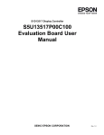
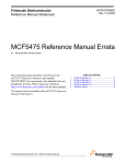
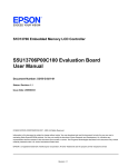
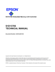
1
S2D13515 Display Controller
S5U13515P00C100
Evaluation Board User
Manual
SEIKO EPSON CORPORATION
Rev 1.1
NOTICE
No part of this material may be reproduced or duplicated in any form or by any means without the written permission of Seiko
Epson. Seiko Epson reserves the right to make changes to this material without notice. Seiko Epson does not assume any liability of any kind arising out of any inaccuracies contained in this material or due to its application or use in any product or circuit and, further, there is no representation that this material is applicable to products requiring high level reliability, such as,
medical products. Moreover, no license to any intellectual property rights is granted by implication or otherwise, and there is
no representation or warranty that anything made in accordance with this material will be free from any patent or copyright
infringement of a third party. This material or portions thereof may contain technology or the subject relating to strategic
products under the control of the Foreign Exchange and Foreign Trade Law of Japan and may require an export license from
the Ministry of International Trade and Industry or other approval from another government agency.
All other product names mentioned herein are trademarks and/or registered trademarks of their respective companies.
©SEIKO EPSON CORPORATION 2008 - 2009, All rights reserved.
Table of Contents
Chapter 1 Introduction . . . . . . . . . . . . . . . . . . . . . . . . . . . . . . . . . . . . 5
Chapter 2 Features . . . . . . . . . . . . . . . . . . . . . . . . . . . . . . . . . . . . . . 6
Chapter 3 Installation and Configuration
3.1 CNF[7:0] Configuration Inputs . . .
3.1.1 CNF[2:0] . . . . . . . . . . .
3.1.2 CNF[7:3] . . . . . . . . . . .
3.1.3 Host Interface Configuration .
3.2 Configuration Jumpers . . . . . .
. . . . . .
. . . . .
. . . . . . .
. . . . . . .
. . . . . . .
. . . . .
.
.
.
.
.
.
. . . . . . .
. . . . . .
. . . . . . . .
. . . . . . . .
. . . . . . . .
. . . . . .
. 7
.7
. 7
. 8
. 9
10
Chapter 4 Technical Description . . . . . . . . . . . . . . . . . . . . .
4.1 Power . . . . . . . . . . . . . . . . . . . . . . . . . .
4.1.1 Power Requirements . . . . . . . . . . . . . . . . . . . . . . . .
4.1.2 Voltage Regulators . . . . . . . . . . . . . . . . . . . . . . . . .
4.1.3 S2D13515 Power . . . . . . . . . . . . . . . . . . . . . . . . . .
4.1.4 LCD Backlight Power . . . . . . . . . . . . . . . . . . . . . . . .
4.2 Clocks . . . . . . . . . . . . . . . . . . . . . . . . . .
4.3 Reset . . . . . . . . . . . . . . . . . . . . . . . . . . .
4.4 Memory . . . . . . . . . . . . . . . . . . . . . . . . . .
4.4.1 SDRAM . . . . . . . . . . . . . . . . . . . . . . . . . . . . . . .
4.4.2 Serial Flash Memory with SPI interface . . . . . . . . . . . . . .
4.5 Host Interface . . . . . . . . . . . . . . . . . . . . . . .
4.5.1 Direct Host Bus Interface Support . . . . . . . . . . . . . . . . .
4.5.2 Connecting to the Epson S5U13U00P00C100 USB Adapter Board
4.6 LCD Interface . . . . . . . . . . . . . . . . . . . . . . .
4.6.1 FP1IO Interface . . . . . . . . . . . . . . . . . . . . . . . . . . .
4.6.2 FP2IO Interface . . . . . . . . . . . . . . . . . . . . . . . . . . .
4.7 Camera / I2C Interface . . . . . . . . . . . . . . . . . . . .
4.8 Keypad Interface . . . . . . . . . . . . . . . . . . . . . .
4.9 I2S Interface . . . . . . . . . . . . . . . . . . . . . . . .
4.10 PWM Connector . . . . . . . . . . . . . . . . . . . . . .
4.11 C33 Debugger Port . . . . . . . . . . . . . . . . . . . . .
4.12 JTAG Interface . . . . . . . . . . . . . . . . . . . . . . .
.
.
.
.
.
.
.
.
.
.
.
.
.
.
.
.
.
.
.
.
.
.
.
. . . . . . .
. . . . . .
. . . . . . . .
. . . . . . . .
. . . . . . . .
. . . . . . . .
. . . . . .
. . . . . .
. . . . . .
. . . . . . . .
. . . . . . . .
. . . . . .
. . . . . . . .
. . . . . . . .
. . . . . .
. . . . . . . .
. . . . . . . .
. . . . . .
. . . . . .
. . . . . .
. . . . . .
. . . . . .
. . . . . .
15
15
15
15
15
15
16
16
17
17
17
17
17
18
19
19
19
20
21
22
23
24
25
Chapter 5 Parts List
. . .
. .
. . .
. . .
. . .
. .
. . . .
. . . .
. . . . .
. . . . .
. . . . .
. . . .
. . .
. .
. . .
. . .
. . .
. .
.
.
.
.
.
.
. . . . . . . . . . . . . . . . . . . . . . . . . . . . . . . . . . . . 26
Chapter 6 Schematic Diagrams . . . . . . . . . . . . . . . . . . . . . . . . . . . . . . 29
Chapter 7 Board Layout . . . . . . . . . . . . . . . . . . . . . . . . . . . . . . . . . . 34
S5U13515P00C100 Evaluation Board User Manual (Rev 1.1)
EPSON
3
Chapter 8 References . . . . . . . . . . . . . . . . . . . . . . . . . . . . . . . . . . . .36
8.1 Documents . . . . . . . . . . . . . . . . . . . . . . . . . . . . . . . .36
8.2 Document Sources . . . . . . . . . . . . . . . . . . . . . . . . . . . . .36
4
EPSON
S5U13515P00C100 Evaluation Board User Manual (Rev 1.1)
Chapter 1 Introduction
Chapter 1 Introduction
This manual describes the setup and operation of the S5U13515P00C100 Evaluation Board. The evaluation board
is designed as an evaluation platform for the S2D13515 Display Controller.
The S5U13515P00C100 evaluation board can be used with many native platforms via the host connector which
provides the appropriate signals to support a variety of CPUs. The S5U13515P00C100 evaluation board can also
connect to the S5U13U00P00C100 USB Adapter board so that it can be used with a laptop or desktop computer, via
USB 2.0.
This user manual is updated as appropriate. Please check the Epson Research and Development Website at
www.erd.epson.com for the latest revision of this document before beginning any development.
We appreciate your comments on our documentation. Please contact us via email at [email protected].
S5U13515P00C100 Evaluation Board User Manual (Rev 1.1)
EPSON
5
Chapter 2 Features
Chapter 2 Features
The S5U13515P00C100 Evaluation Board includes the following features:
• 256-pin PBGA S2D13515 Display Controller
• On-board SDRAM, configurable as 32MB (32-bit wide) or 16MB (16-bit wide)
• On-board Serial Flash Memory, 32Mbit
• Headers for connection to various Host Bus Interfaces (includes all S2D13515 Host Bus Interface signals)
• Headers for connection to the S5U13U00P00C100 USB Adapter board
• Headers for connection to various LCD panels (includes all S2D13515 FP1IO and FP2IO interface signals)
• Header for connection to cameras
• Header for I2S outputs
• On-board 3x3 keypad
• On-board 20MHz crystal
• 14-pin DIP socket (if an oscillator for CLKI input is required)
• 3.3V input power
• On-board voltage regulator with 1.8V output
• On-board voltage regulator with adjustable 12~25V output, 60~100mA max., to provide power for LED backlight of LCD panels.
6
EPSON
S5U13515P00C100 Evaluation Board User Manual (Rev 1.1)
Chapter 3 Installation and Configuration
Chapter 3 Installation and Configuration
The S5U13515P00C100 evaluation board incorporates a DIP switch, jumpers, and 0 ohm resistors which allow it to
be used with a variety of different configurations.
3.1 CNF[7:0] Configuration Inputs
The S2D13515 has 8 configuration inputs (CNF[7:0]), which can be configured through a combination of a DIP
switch and 0 ohm resistors. CNF[2:0] are dedicated inputs and are configured using DIP switch SW1. CNF[7:3] are
multiplexed with some host interface signals and are configured by 0 ohm resistors.
3.1.1 CNF[2:0]
CNF[2:0] are configured using DIP switch SW1 as described below.
Table 3-1: CNF[2:0] Configuration Settings
CNF[2:0]
CNF2
CNF1
CNF0
1 (connected to HIOVDD)
0 (connected to VSS)
CNF[2:1] are used in combination with CNF[7:3] to select the host bus interface. For a
summary of the possible host bus interfaces, see Section Table 3-3 :, “Host Interface
Configuration Settings” on page 9.
OSCI is the source for Input Clock 1
CLKI is the source for Input Clock 1
= suggested settings
The following figure shows the location of DIP switch SW1 on the S5U13515P00C100 evaluation board.
Figure 3-1: Configuration DIP Switch (SW1) Location
S5U13515P00C100 Evaluation Board User Manual (Rev 1.1)
EPSON
7
Chapter 3 Installation and Configuration
3.1.2 CNF[7:3]
CNF[7:3] are configured using 0 Ohm resistors as described below.
Table 3-2: CNF[7:3] Configuration Settings
CNF
Pin
1 (connected to HIOVDD)
0 (connected to VSS)
TEA#
R100 populated
R107 not populated
R100 not populated
R107 populated
AB0
R99 populated
R106 not populated
R99 not populated
R106 populated
CNF4
BDIP#
R95 populated
R102 not populated
R95 not populated
R102 populated
CNF5
BURST#
R96 populated
R103 not populated
R96 not populated
R103 populated
AB3
R98 populated
R105 not populated
R98 not populated
R105 populated
BE1#
R97 populated
R104 not populated
R97 not populated
R104 populated
AB0
R99 populated
R106 not populated
R99 not populated
R106 populated
AB4
R101 populated
R108 not populated
R101 not populated
R108 populated
CNF3
(see Note)
CNF6
(see Note)
CNF7
= default settings, required settings when using S5U13U00P00C100 USB Adapter Board
Note
CNF3 and CNF6 are mapped to different pins depending on the combination of the other CNF inputs.
The following figure shows the location of the 0 Ohm resistors used to configure CNF[7:3].
Figure 3-2: CNF[7:3] 0 Ohm Resistor Locations
8
EPSON
S5U13515P00C100 Evaluation Board User Manual (Rev 1.1)
Chapter 3 Installation and Configuration
3.1.3 Host Interface Configuration
The host bus interface used by the S5U13515P00C100 evaluation board is selected using a combination of the
CNF[2:1] pins and unused host interface pins. Many host bus interfaces have unused pins that can be used as configuration pins (CNF[7:3]) to select the host bus interface. The following table summarizes the available settings.
Table 3-3 : Host Interface Configuration Settings
CNF1
0
0
0
0
0
0
0
0
0
0
0
0
0
0
0
0
0
0
0
0
0
0
0
0
0
0
0
0
0
1
1
1
1
CNF2
0
0
0
0
0
0
0
1
1
1
1
1
1
1
0
0
0
0
0
0
0
1
1
1
1
1
1
1
1
0
0
1
1
X
CNF3
0 (TEA#)
0 (TEA#)
0 (TEA#)
0 (TEA#)
0 (TEA#)
0 (TEA#)
0 (TEA#)
0 (TEA#)
0 (TEA#)
0 (TEA#)
0 (TEA#)
0 (TEA#)
0 (TEA#)
0 (TEA#)
1 (TEA#)
1 (TEA#)
1 (TEA#)
1 (TEA#)
1 (TEA#)
1 (TEA#)
1 (TEA#)
1 (TEA#)
1 (TEA#)
1 (TEA#)
1 (TEA#)
1 (TEA#)
1 (TEA#)
1 (TEA#)
1 (TEA#)
0 (AB0)
1 (AB0)
0 (BE1#)
1 (BE1#)
CNF4
0 (BDIP#)
0 (BDIP#)
0 (BDIP#)
0 (BDIP#)
1 (BDIP#)
1 (BDIP#)
1 (BDIP#)
0 (BDIP#)
0 (BDIP#)
0 (BDIP#)
0 (BDIP#)
1 (BDIP#)
1 (BDIP#)
1 (BDIP#)
0 (BDIP#)
0 (BDIP#)
0 (BDIP#)
0 (BDIP#)
1 (BDIP#)
1 (BDIP#)
1 (BDIP#)
0 (BDIP#)
0 (BDIP#)
0 (BDIP#)
0 (BDIP#)
0 (BDIP#)
1 (BDIP#)
1 (BDIP#)
1 (BDIP#)
X
X
X
X
CNF5
0 (BURST#)
0 (BURST#)
1 (BURST#)
1 (BURST#)
0 (BURST#)
0 (BURST#)
1 (BURST#)
0 (BURST#)
0 (BURST#)
1 (BURST#)
1 (BURST#)
0 (BURST#)
0 (BURST#)
1 (BURST#)
0 (BURST#)
0 (BURST#)
1 (BURST#)
1 (BURST#)
0 (BURST#)
0 (BURST#)
1 (BURST#)
0 (BURST#)
0 (BURST#)
1 (BURST#)
1 (BURST#)
1 (BURST#)
0 (BURST#)
0 (BURST#)
1 (BURST#)
X
X
X
X
CNF6
0 (AB3)
1 (AB3)
1 (AB3)
1 (AB3)
0 (AB3)
1 (AB3)
0 (AB3)
0 (AB3)
1 (AB3)
1 (AB3)
1 (AB3)
0 (AB3)
1 (AB3)
0 (AB3)
0 (BE1#)
1 (BE1#)
1 (BE1#)
1 (BE1#)
0 (BE1#)
1 (BE1#)
0 (BE1#)
0 (AB0)
1 (AB0)
0 (AB0)
1 (AB0)
1 (AB0)
0 (AB0)
1 (AB0)
0 (AB0)
X
X
X
X
CNF7
X
X
0 (AB4)
1 (AB4)
X
X
X
X
X
0 (AB4)
1 (AB4)
X
X
X
X
X
0 (AB4)
1 (AB4)
X
X
X
X
X
X
0 (AB4)
1 (AB4)
X
X
X
X
X
X
X
Host Interface
Indirect, 8-bit, Intel80 Type1
Indirect, 8-bit, Intel80 Type2
SPI
I2C
Indirect, 8-bit, NEC V850 Type1
Indirect, 8-bit, NEC V850 Type2
Indirect, 8-bit, Renesas SH4
Indirect, 16-bit, Intel80 Type1
Indirect, 16-bit, Intel80 Type2
SPI (2-stream)
I2C
Indirect, 16-bit, NEC V850 Type1
Indirect, 16-bit, NEC V850 Type2
Indirect, 16-bit, Renesas SH4
Direct, 8-bit, Intel80 Type1
Direct, 8-bit, Intel80 Type2
SPI
I2C
Direct, 8-bit, NEC V850 Type1
Direct, 8-bit, NEC V850 Type2
Direct, 8-bit, Renesas SH4
Direct, 16-bit, Intel80 Type1
Direct, 16-bit, Intel80 Type2
Direct, 16-bit, Intel PXA3xxs
SPI
I2C
Direct, 16-bit, NEC V850 Type1
Direct, 16-bit, NEC V850 Type2
Direct, 16-bit, Renesas SH4
Indirect, 16-bit, TI EBI
Direct, 16-bit, TI EBI
Indirect, 16-bit, MPC555
Direct, 16-bit, MPC555
= default settings, required settings when using S5U13U00P00C100 USB Adapter Board
= don’t care
S5U13515P00C100 Evaluation Board User Manual (Rev 1.1)
EPSON
9
Chapter 3 Installation and Configuration
3.2 Configuration Jumpers
The S5U13515P00C100 has 16 jumpers which configure various evaluation board settings. The jumper positions
for each function are shown below.
Table 3-4: Configuration Jumper Settings
Jumper
Function
Position 1-2
Position 2-3
No Jumper
JP1
COREVDD
Normal
—
COREVDD current measurement
JP2
PLL1VDD
Normal
—
PLL1VDD current measurement
JP3
PLL2VDD
Normal
—
PLL2VDD current measurement
JP4
OSCVDD
Normal
—
OSCVDD current measurement
JP5
PIO1VDD
Normal
—
PIO1VDD current measurement
JP6
HIOVDD
Normal
—
HIOVDD current measurement
JP7
HIOVDD Source
H4 connector, pin 31
3.3VDD
—
JP8
PIO1VDD Source
H9 connector, pin 9
3.3VDD
—
JP9
PIO2VDD Source
H9 connector, pin 10
3.3VDD
—
JP10
CM1VDD
Normal
—
CM1VDD current measurement
JP11
PIO2VDD
Normal
—
PIO2VDD current measurement
JP12
CM1DD Source
H9 connector, pin 8
3.3VDD
—
JP13
IOVDD Source
H9 connector, pin 7
3.3VDD
—
JP14
IOVDD
Normal
—
IOVDD current measurement
JP15
SDVDD
Normal
—
SDVDD current measurement
JP16
SDRAM Width Select
(see Note)
32-bit wide SDRAM
16-bit wide SDRAM
—
= Required settings when using S5U13U00P00C100 USB Adapter board
10
EPSON
S5U13515P00C100 Evaluation Board User Manual (Rev 1.1)
Chapter 3 Installation and Configuration
JP1, JP2, JP3, JP4, JP5, JP6, JP10, JP11, JP14, JP15 - Power Supplies for the S2D13515
JP1, JP2, JP3, JP4, JP5, JP6, JP10, JP11, JP14, and JP15 can be used to measure the current consumption of each
S2D13515 power supply.
When the jumper is at position 1-2, normal operation is selected.
When no jumper is installed, the current consumption for each power supply can be measured by connecting an
ammeter to pin 1 and 2 of the jumper.
The jumper associated with each power supply is as follows:
JP1 for COREVDD
JP3 for PLL2VDD
JP5 for PIO1VDD
JP10 for CM1VDD
JP14 for IOVDD
JP2 for PLL1VDD
JP4 for OSCVDD
JP6 for HIOVDD
JP11 for PIO2VDD
JP15 for SDVDD
Figure 3-3: Configuration Jumper Locations (JP1, JP2, JP3, JP4, JP5, JP6, JP10, JP11, JP14, JP15)
S5U13515P00C100 Evaluation Board User Manual (Rev 1.1)
EPSON
11
Chapter 3 Installation and Configuration
JP7 - HIOVDD Source
JP7 is used to select the source for the HIOVDD supply voltage.
When the jumper is at position 1-2, the HIOVDD voltage must be provided to pin 31 on the H4 connector.
When the jumper is at position 2-3, the HIOVDD voltage is provided by the 3.3V power supply of the board.
Figure 3-4: Configuration Jumper Location (JP7)
JP8 - PIO1VDD Source
JP8 is used to select the source for the PIO1VDD supply voltage.
When the jumper is at position 1-2, the PIO1VDD voltage must be provided to pin 9 on the H9 connector.
When the jumper is at position 2-3, the PIO1VDD voltage is provided by the 3.3V power supply of the board.
Figure 3-5: Configuration Jumper Location (JP8)
12
EPSON
S5U13515P00C100 Evaluation Board User Manual (Rev 1.1)
Chapter 3 Installation and Configuration
JP9 - PIO2VDD Source
JP9 is used to select the source for the PIO2VDD supply voltage.
When the jumper is at position 1-2, the PIO2VDD voltage must be provided to pin 10 on the H9 connector.
When the jumper is at position 2-3, the PIO2VDD voltage is provided by the 3.3V power supply of the board.
Figure 3-6: Configuration Jumper Location (JP9)
JP12 - CM1VDD Source
JP12 is used to select the source for the CM1VDD supply voltage.
When the jumper is at position 1-2, the CM1VDD voltage must be provided to pin 8 on the H9 connector.
When the jumper is at position 2-3, the CM1VDD voltage is provided by the 3.3V power supply of the board.
Figure 3-7: Configuration Jumper Location (JP12)
S5U13515P00C100 Evaluation Board User Manual (Rev 1.1)
EPSON
13
Chapter 3 Installation and Configuration
JP13 - IOVDD Source
JP13 is used to select the source for the IOVDD supply voltage.
When the jumper is at position 1-2, the IOVDD voltage must be provided to pin 7 on the H9 connector.
When the jumper is at position 2-3, the IOVDD voltage is provided by the 3.3V power supply of the board.
Figure 3-8: Configuration Jumper Location (JP13)
JP16 - SDRAM Width Select
JP16 is used to select the bus width of the external SDRAM.
When the jumper is at position 1-2, the external SDRAM is 32 bits wide and the memory size is 32M bytes. In this
configuration, the memory consists of 2 chips in parallel, each16M bytes and 16 bits wide.
When the jumper is at position 2-3, the external SDRAM is 16 bits wide and the memory size is 16M bytes. In this
configuration, one memory chip is disabled and only one chip is active (16M bytes and 16 bits wide).
Figure 3-9: Configuration Jumper Location (JP16)
14
EPSON
S5U13515P00C100 Evaluation Board User Manual (Rev 1.1)
Chapter 4 Technical Description
Chapter 4 Technical Description
4.1 Power
4.1.1 Power Requirements
The S5U13515P00C100 evaluation board requires an external regulated power supply (3.3V / 1A). The power is
supplied to the evaluation board through pin 33 of the H4 header, or pin 5 of the P2 header.
The green LED “3.3V Power” is turned on when 3.3V power is applied to the board.
4.1.2 Voltage Regulators
The S5U13515P00C100 evaluation board has an on-board linear regulator to provide the 1.8V power required by
the S2D13515 Display Controller. It also has a step-up switching voltage regulator to generate adjustable 12~25V,
which can be used to power the LED backlight on some LCD panels.
4.1.3 S2D13515 Power
The S2D13515 Display Controller requires 1.8V power and 2.3~2.7V or 3.0~3.6V power.
COREVDD, PLL1VDD, PLL2VDD, and OSCVDD require 1.8V power which is provided by an on-board linear
voltage regulator.
HIOVDD, PIO1VDD, PIO2VDD, CM1VDD, and IOVDD input power may be in the range 2.3V~2.7V or
3.0V~3.6V. When JP7, JP8, JP9, JP12, or JP13 are set to the 2-3 position, the corresponding power input is
connected to 3.3V. If a different voltage is required, set the corresponding jumper to the 1-2 position and connect
the external power supply to the evaluation board as indicated in Table 3-4: “Configuration Jumper Settings,” on
page 10.
SDVDD input power may be in the range 2.3V~2.7V or 3.0V~3.6V. On the evaluation board, SDVDD is connected
to 3.3V.
4.1.4 LCD Backlight Power
On the evaluation board there is an adjustable 12~25V power supply. At 12V, the maximum current available is
100mA. At 25V, the maximum current available is 60mA. This power supply is intended for use to power the LED
backlight on some LCD panels. The voltage is adjusted by the R175 pot.
Note
For LCD panels that use a CCFL backlight, an external power supply must be used to provide power to the inverter
for the CCFL backlight. Usually, the inverter current consumption is higher than the maximum 100mA current
available from the on-board voltage regulator.
S5U13515P00C100 Evaluation Board User Manual (Rev 1.1)
EPSON
15
Chapter 4 Technical Description
4.2 Clocks
The clock for the S2D13515 Display Controller is provided by a 20MHz crystal connected to the OSCI and OSCO
pins.
Additionally, the S5U13515P00C100 evaluation board can also use an oscillator if the DIP14 footprint is populated.
If populated, the oscillator is connected to the CLKI input clock of the S2D13515 Display controller.
Note
For details on the S2D13515 clock structure, refer to the S2D13515 Hardware Functional Specification, document
number X83A-A-001-xx.
4.3 Reset
The S2D13515 Display Controller on the S5U13515P00C100 evaluation board can be reset using a push-button
switch (SW2), or via an active low reset signal from the host development platform (pin 30 on the H4 connector).
Figure 4-1: Reset Switch (SW2) Location
16
EPSON
S5U13515P00C100 Evaluation Board User Manual (Rev 1.1)
Chapter 4 Technical Description
4.4 Memory
4.4.1 SDRAM
The S5U13515P00C100 evaluation board has 2 SDRAM ICs, each 128Mbit x16-bit, CL=2 in a TSOP54 package.
When the S2D13515 Display Controller is configured for 32-bit wide DRAM bus, both SDRAM ICs are used. When
the S2D13515 Display Controller is configured for 16-bit wide DRAM bus, only one of the SDRAM ICs is used
and the other SDRAM ICs is disabled by having its chip select input pulled high to inactive state, by putting jumper
JP16 in 2-3 position.
4.4.2 Serial Flash Memory with SPI interface
The S2D13515 Display Controller has a SPI Flash Memory interface which is connected to a 32Mbit Flash EPROM.
4.5 Host Interface
4.5.1 Direct Host Bus Interface Support
All S2D13515 host interface pins are available on connectors H3 and H4. This allows the S5U13515P00C100 evaluation board to be connected to a variety of development platforms. For S2D13515 host interface pin mapping, refer
to the S2D13515 Hardware Functional Specification, document number X83A-A-001-xx.
The following figure shows the location of host bus connectors H3 and H4. H3 is a 0.1” x 0.1” 40-pin header (20x2)
and H4 is a 0.1” x 0.1” 34-pin header (17 x 2).
Figure 4-2: Host Bus Connector Location (H3 and H4)
For the pinout of connectors H3 and H4, see Section Chapter 6, “Schematic Diagrams” on page 29.
S5U13515P00C100 Evaluation Board User Manual (Rev 1.1)
EPSON
17
Chapter 4 Technical Description
4.5.2 Connecting to the Epson S5U13U00P00C100 USB Adapter Board
The S5U13515P00C100 evaluation board is designed to connect to a S5U13U00P00C100 USB Adapter Board. The
USB adapter board provides a simple connection to any computer via a USB 2.0 connection. The
S5U13515P00C100 directly connects to the USB adapter board through connectors P1 and P2.
The USB adapter board also supplies the 3.3V power required by the S5U13515P00C100 evaluation board.
HIOVDD should be configured for 3.3V and JP7 should be set to the 2-3 position.
When the S5U13515P00C100 is connected to the S5U13U00P00C100 USB Adapter board, there are 2 LEDs on the
S5U13515P00C100 which provide a quick visual status of the USB adapter. LED1 blinks to indicate that the USB
adapter board is active. LED2 turns on to indicate that the USB has been enumerated by the PC.
The following diagram shows the location of connectors P1 and P2. P1 and P2 are 2mm x 2mm, 40-pin headers
(20 x 2) located on the underside of the board.
Figure 4-3: USB Adapter Connector Locations (P1 and P2)
For the pinout of connectors P1 and P2, see Section Chapter 6, “Schematic Diagrams” on page 29.
Note
A windows driver must be installed on the PC when the S5U13515P00C100 is used with the S5U13U00P00C100
USB Adapter Board. The S1D13xxxUSB driver is available at www.erd.epson.com.
18
EPSON
S5U13515P00C100 Evaluation Board User Manual (Rev 1.1)
Chapter 4 Technical Description
4.6 LCD Interface
The LCD interface uses the FP1IO[23:0] and FP2IO[27:0] pins. All signals on these pins are available on connectors
H5, H6, and H7.
Connectors H5, H6, and H7 are 0.1” x 0.1”, 40-pin headers (20 x 2). The following diagram shows the location of
these connectors.
Figure 4-4: FP1IO and FP2IO Connectors Location (H5, H6, H7)
For the pinout of connectors H5, H6, and H7, see Section Chapter 6, “Schematic Diagrams” on page 29.
4.6.1 FP1IO Interface
The FP1IO interface signals have multiplexed functions. All FP1IO interface signals, except FP1IO18 and FP1IO19,
are available on connector H6. FP1IO18 and FP1IO19 signals go through 0 ohm resistors and are available on
connector H7.
The FP1IO interface can be configured as a LCD interface, 18-bit RGB input stream interface, or 8-bit YUV camera
interface and keyboard interface. For S2D13515 FP1IO interface pin mapping, refer to the S2D13515 Hardware
Functional Specification, document number X83A-A-001-xx.
4.6.2 FP2IO Interface
All FP2IO interface signals are available on connectors H5 and H7. For S2D13515 FP2IO interface pin mapping,
refer to the S2D13515 Hardware Functional Specification, document number X83A-A-001-xx.
S5U13515P00C100 Evaluation Board User Manual (Rev 1.1)
EPSON
19
Chapter 4 Technical Description
4.7 Camera / I2C Interface
The S2D13515 Display Controller has a Camera interface. All the camera interface signals are available on
connector H10. To control the camera, the S2D13515 Display Controller has an I2C master interface. The SDA and
SCL signals are pulled high to CM1VDD by 2.2 kΩ resistors and are available on connector H10. The reset signal
provided on H10 is active low and is pulled to HIOVDD when inactive.
Connector H10 is a 0.1” x 0.1”, 20-pin header (10 x 2). The following figure shows the location of the connector
H10.
Figure 4-5: Camera Connector Location (H10)
For the pinout of connector H10, see Section Chapter 6, “Schematic Diagrams” on page 29.
20
EPSON
S5U13515P00C100 Evaluation Board User Manual (Rev 1.1)
Chapter 4 Technical Description
4.8 Keypad Interface
Note
The keyboard is non-operational with the buttons SW3-SW11, mounted as they are on the board. In order to make
the keyboard operational, the user must remove the buttons SW3-SW11 from the board and mount them back on
the board, but rotated by 90 degrees or 270 degrees. The buttons will not match the footprint on the PCB, but this is
how they must be mounted on the board.
The S2D13515 Display Controller can support up to a 5x5 matrix keypad, but the S5U13515P00C100 evaluation
board includes only a 3x3 keypad. The keypad interface can be configured to use either the FPIO1 interface or Host
interface pins. For S2D13515 pin mapping, refer to the S2D13515 Hardware Functional Specification, document
number X83A-A-001-xx. The keypad interface is configured for either the FPIO1 interface or Host Interface pins
using 0 ohm resistors.
M/R#, AB[20:19], AB[16:14]
S2D13515
FP1IO[23:20], FP1IO[16:15]
Zero
Ohms
3x3
Keypad
Zero
Ohms
Figure 4-6: Keypad Interface Zero Ohm Resistor Overview Diagram
The keypad can be configured to connect to 1 of 2 source pins on the S2D13515. Depending of the configuration,
the input lines must be pulled high to corresponding power supply. The source connection for the keypad is determined by populating the correct set of zero ohm resistors as described below.
Table 4-1: Keypad Zero Ohm Resistor Summary
Keypad Pin Function
KBR0
KBR1
KBR2
KBC0
KBC1
KBC2
Power
(HIOVDD or PIO1VDD)
Populate only 1 set of the zero ohm resistors below
Zero Ohm For FP1IO
Zero Ohm For Host Interface
R191
R185
R192
R186
R193
R187
R194
R188
R195
R190
R196
R189
R181
R180
S5U13515P00C100 evaluation board comes configured with the keyboard interface from the Host Interface pins,
so resistors R185 ~ R190 and R180 are populated and R191 ~ R196 and R181 are not populated.
S5U13515P00C100 Evaluation Board User Manual (Rev 1.1)
EPSON
21
Chapter 4 Technical Description
4.9 I2S Interface
The S2D13515 Display Controller has an I2S Audio output interface. All of the I2S interface signals are available
on connector H8. The I2C signals, available on the same connector, can be used to program an external I2S Audio
DAC IC.
Connector H8 is a 0.1” x 0.1”, 24-pin header (12x2). The following figure shows the location of the connector H8.
Figure 4-7: I2S Connector Location (H8)
For the pinout of connector H8, see Section Chapter 6, “Schematic Diagrams” on page 29.
22
EPSON
S5U13515P00C100 Evaluation Board User Manual (Rev 1.1)
Chapter 4 Technical Description
4.10 PWM Connector
The S2D13515 Display Controller has two PWM outputs which are available on connector H9. The other pins on
connector H9 are used to connect the external power supplies to CM1VDD, IOVDD, PIO1VDD, and PIO2VDD, if
a voltage level different than 3.3V is required. Note that connector H9 is not populated on the S5U13515P00C100
evaluation board.
Connector H9 is a 0.1” x 0.1”, 10-pin header (5x2). The following figure shows the location of the connector H9.
Figure 4-8: PWM Connector Location (H9)
For the pinout of connector H9, see Section Chapter 6, “Schematic Diagrams” on page 29.
S5U13515P00C100 Evaluation Board User Manual (Rev 1.1)
EPSON
23
Chapter 4 Technical Description
4.11 C33 Debugger Port
The S2D13515 contains an embedded C33 microprocessor core. The debug monitor interface is available on
connector H2 for firmware debugging using C33 Debugger. In order to use connector H2, zero ohm resistors must
be configured depending on the desired S2D13515 configuration.
The C33 debugger function can be sourced from 2 sets of the host interface pins or from a set of FP2IO pins.
S2D13515
AB[11:7], AB6 or BS#
Zero
Ohms
FP2IO[17, 16, 14, 13, 11, 10]
Zero
Ohms
DB[13:8]
Zero
Ohms
H2
C33
Debugger
Port
Figure 4-9: C33 Debugger Zero Ohm Resistor Overview Diagram
The connection to the C33 Debugger port is determined by populating the correct set of zero ohm resistors as
described below.
Table 4-2: C33 Debugger Port H7 Zero Ohm Selection
Populate only 1 set of the zero ohm resistors below
C33 Pin Function
C33 Debugger port
from FP2IO pins
C33 Debugger port from
AB[11:7], AB6 or BS# pins
C33 Debugger port from
DB[13:8] pins
PEDST0
R74 populated
R210 not populated
R65 populated
R202 not populated
R80 populated
R208 not populated
PEDST1
R73 populated
R211 not populated
R66 populated
R201 not populated
R79 populated
R207 not populated
PEDST2
R72 populated
R212 not populated
R67 populated
R200 not populated
R78 populated
R206 not populated
PEDCLK
R70 populated
R213 not populated
R69 populated
R199 not populated
R76 populated
R205 not populated
PEDSIO
R71 populated
R215 not populated
R68 populated
R198 not populated
R77 populated
R204 not populated
PEDCPCO
R75 populated
R214 not populated
R63 populated (from AB6)
R64, R197 not populated
R64 populated (from BS#)
R63, R209 not populated
R81 populated
R203 not populated
S5U13515P00C100 board comes configured for the C33 Debugger port from the Host Interface AB[11:6] pins, so
resistors R63, R65 ~ R69 are populated and R197 ~ R202 are not populated, R203 ~ R215 are populated and R64,
R70 ~ R81 are not populated.
24
EPSON
S5U13515P00C100 Evaluation Board User Manual (Rev 1.1)
Chapter 4 Technical Description
Connector H2 is a 0.1” x 0.1”, 10-pin header (5x2). The following figure shows the location of the connector H2.
Figure 4-10: C33 Debugger Connector Location (H2)
For the pinout of connector H2, see Section Chapter 6, “Schematic Diagrams” on page 29.
4.12 JTAG Interface
The S2D13515 Display Controller has a JTAG interface. All the JTAG signals are available on connector H1. Note
that connector H1 is not populated on the S5U13515P00C100 evaluation board.
Connector H1 is a 0.1” x 0.1”, 12-pin header (6x2). The following figure shows the location of the connector H1.
Figure 4-11: JTAG Connector Location (H1)
For the pinout of connector H1, see Section Chapter 6, “Schematic Diagrams” on page 29.
S5U13515P00C100 Evaluation Board User Manual (Rev 1.1)
EPSON
25
Chapter 5 Parts List
Chapter 5 Parts List
Table 5-1 : S5U13515P00C100 Parts List
Item
Quantity
Reference
Part
Description
50
C1,C2,C3,C4,C5,C6,C7,C
8,C17,C20,C24,C25,C26,
C27,C28,C29,C30,C31,C3
9,C40,C41,C42,C43,C49,
C50,C51,C52,C53,C54,C5
5,C63,C67,C69,C71,C72,
C74,C75,C76,C77,C78,C7
9,C80,C81,C82,C83,C84,
C85,C86,C87,C106
0.1uF
Yageo America 04022F104Z7B20D, C0402
2
43
C9,C10,C11,C12,C13,C14
,C15,C16,C23,C32,C33,C
34,C35,C36,C37,C38,C44,
C45,C46,C47,C48,C56,C5
7,C58,C59,C60,C61,C62,
C68,C88,C89,C90,C91,C9
2,C93,C94,C95,C96,C97,
C98,C99,C100,C101
0.01uF
Yageo America 0402ZRY5V7BB103, C0402
3
2
C18,C21
1nF
Yageo America 04022R102K9B20D, C0402
4
5
C19,C22,C64,C70,C73
10uF
Panasonic - ECG ECJ-CV50J106M, C0805
5
2
C65,C66
18pF
Panasonic - ECG ECJ-0EC1H180J, C0402
6
1
C102
2.2uF 10V
Taiyo Yuden LMK212BJ225KG-T, C0805,
CAP CER 2.2UF 10V X7R 0805
7
1
C103
10uF 35V
Taiyo Yuden GMK325BJ106KN-T, C1210,
CAP CER 10UF 35V X5R 1210
8
1
C104
150pF
Panasonic - ECG ECJ-0EC1H151J, C0402
9
1
C105
1uF
Panasonic - ECG ECJ-0EB0J105M, C0402
10
3
D1,D2,D3
11
10
D4,D5,D6,D7,D8,D9,D10,
D11,D12,D13
MBR0540
Micro Commercial Co. MBR0540-TP, SOD-123,
DIODE SCHOTTKY 40V 500MA SOD123
12
1
F1
ACH32C-333-T
TDK ACH32C-333-T,
FILTR 3TERM 10MHZ TO 300MHZ SMD
13
1
F2
ACF451832-222
TDK ACF451832-222,
FILTER 3-TERM 60MHZ 300MA SMD
14
0
H1
JTAG
Samtec TSW-106-07-G-D
Do not populate
15
1
H2,H9
16
1
H3
HEADER_20X2
Samtec TSW-120-07-G-D
17
1
H4
HEADER_17X2
Samtec TSW-117-07-G-D
18
3
H5,H6,H7
19
1
H8
I2S PORT
Samtec TSW-112-07-G-D
20
1
H10
CAMERA1
Samtec TSW-110-07-G-D
1
26
Panasonic - SSG LNJ308G8LRA, LED0603,
LED GREEN SS TYPE LOW CUR SMD
Samtec TSW-105-07-G-D, Do not populate H9
Samtec TST-120-01-G-D
EPSON
S5U13515P00C100 Evaluation Board User Manual (Rev 1.1)
Chapter 5 Parts List
Table 5-1 : S5U13515P00C100 Parts List
Item
Quantity
Reference
21
10
JP1,JP2,JP3,JP4,JP5,JP6
JP10,JP11,JP14,JP15
SIP2 CONN HEADER VERT 2POS .100 TIN or
GENERIC
22
6
JP7,JP8,JP9,JP12,JP13,J
P16
SIP3 CONN HEADER VERT 3POS .100 TIN or
GENERIC
23
6
L1,L2,L3,L4,L5,L6
Ferrite
Steward HZ0603B751R-10, R0603,
FERRITE 200MA 938 OHMS 0603 SMD
24
1
L7
10uH
Panasonic - ECG ELL-6SH100M, IND_ELL6,
COIL 10UH 1300MA CHOKE SMD
25
2
P1,P2
HEADER_20X2
3M 151240-8422-RB, HDR2X20/2MM
61
R1,R2,R3,R4,R5,R6,R7,R
8,R9,R10,R11,R12,R13,R
14,R15,R16,R17,R18,R19,
R20,R21,R22,R23,R24,R2
5,R26,R27,R28,R29,R30,
R31,R32,R33,R34,R35,R3
6,R37,R38,R39,R40,R41,
R42,R43,R44,R45,R46,R4
7,R48,R49,R50,R51,R53,
R54,R55,R57,R58,R59,R6
0,R61,R62,R88
33 1%
R0402
0
R52,R64,R70,R71,R72,R7
3,R74,R75,R76,R77,R78,
R79,R80,R81,R95,R96,R9
7,R98,R99,R100,R101,R1
04,R106,R108,R134,R135,
R136,R137,R138,R139,R1
40,R141,R142,R143,R144,
R145,R146,R147,R148,R1
49,R150,R151,R161,R163,
R165,R167,R169,R170,R1
81,R191,R192,R193,R194,
R195,R196,R197,R198,R1
99,R200,R201,R202,R216,
R217,R218,R219
0_np
R0402
Do not populate
28
68
R56,R63,R65,R66,R67,R6
8,R69,R83,R85,R86,R87,
R102,R103,R105,R107,R1
09,R110,R111,R113,R114,
R115,R116,R117,R118,R1
19,R120,R121,R122,R123,
R124,R125,R126,R127,R1
28,R129,R130,R131,R132,
R152,R153,R154,R155,R1
60,R162,R164,R166,R168,
R171,R180,R185,R186,R1
87,R188,R189,R190,R203,
R204,R205,R206,R207,R2
08,R209,R210,R211,R212,
R213,R214,R215
0
R0402
29
1
R82
1M
R0402
30
1
R84
1k
R0402
26
27
Part
S5U13515P00C100 Evaluation Board User Manual (Rev 1.1)
EPSON
Description
27
Chapter 5 Parts List
Table 5-1 : S5U13515P00C100 Parts List
Item
28
Quantity
Reference
Part
Description
31
10
R89,R91,R92,R93,R94,R1
56,R174,R182,R183,R184
10k
R0402
32
1
R90
150k 1%
R0402
33
3
R112,R133,R172
0
R0603
34
3
R157,R158,R159
270 1%
R0402
35
1
R173
120k
R0402
36
1
R175
200k
Panasonic - ECG EVN-5ESX50B25,
POT 200K OHM 3MM CARBON TRIM SMD
37
1
R176
56k
R0402
38
1
R177
13.3k 1%
R0402
39
2
R178,R179
2.2k
R0402
40
16
SH1,SH2,SH3,SH4,SH5,S
H6,SH7,SH8,SH9,SH10,S
H11,SH12,SH13,SH14,SH
15,SH16
.100 in. Jumper
Shunt
Sullins Electronics Corp. STC02SYAN
JUMPER SHORTING TIN
41
1
SW1
SW4_DIPSW4
CTS Corp 218-4LPST, DIPSW4,
SWITCH DIP HALF PITCH 4POS
42
10
SW2,SW3,SW4,SW5,SW6
,SW7,SW8,SW9,SW10,S
W11
SW TACT-SPST
ITT Industries KSC201JLFS,
SWITCH TACT SILVR 120GF J-LEAD
43
2
TPGND1,TP3.3VDD1
TP_SMT
Keystone 5015, TP_1206,
PC TEST POINT MINIATURE SMT
44
1
U1
S2D13515PBGA256
45
1
U2
M25P32-VMF
ST Microelectronics M25P32-VMF6P,
IC SRL FLASH 32MBIT 3V 16-SOIC
46
2
U3,U4
128M16 DRAM
Qimonda HYB39S128160FE-7,
IC SDRAM 128MBit 54-TSOP
47
1
U5
MIC37100-1.8WS
Micrel MIC37100-1.8WS, SOT-223,
Alternate MIC39100-1.8WS
48
1
U6
LM2733Y
National Semiconductor LM2733YMF/NOPB,
SOT23-5,
IC CONV BOOST 40V FET SW SOT23-5
49
1
X1
MA-506 20.0000M
Epson MA-506 20.0000M,
CRYSTAL 20.0000MHZ 18PF SMD
50
0
Y1
14-Pin DIP
AMP 2-641609-1
Do not populate
EPSON
S5U13515P00C100 Evaluation Board User Manual (Rev 1.1)
A
B
C
D
3
TMS
TDI
TDO
TCK
IOVDD
4
4
1
3
5
7
9
11
CM1DAT0
CM1DAT1
CM1DAT2
CM1DAT3
CM1DAT4
CM1DAT5
CM1DAT6
CM1DAT7
CM1FIELD
CM1HREF
CM1VREF
CM1CLKIN
CM1CLKOUT
5
5
5
5
5
5
5
5
5
5
5
5
5
JTAG
H1
PWM1
PWM2
SCL
SDA
WSIO
SCKIO
SDO
MCLKO
4
4
4
4
4,5
4,5
CNF0
CNF1
CNF2
SPICS#
SPICLK
SPIDIO
2
2
2
CLKI
BUSCLK
OSCI
OSCO
2
3
2
2
2
2
2
CS#
M/R#
RD#
RD/WR#
BE0#
BE1#
BS#
BURST#
BDIP#
TEA#
WAIT#
IRQ
RESET#
DB0
DB1
DB2
DB3
DB4
DB5
DB6
DB7
DB8
DB9
DB10
DB11
DB12
DB13
DB14
DB15
AB0
AB1
AB2
AB3
AB4
AB5
AB6
AB7
AB8
AB9
AB10
AB11
AB12
AB13
AB14
AB15
AB16
AB17
AB18
AB19
AB20
3
3,5
3
3
3
2,3
3
2,3
2,3
2,3
3
3
2,3,5
DB[15:0]
AB[20:0]
2
4
6
8
10
12
R12
R14
R16
R209
R203
R204
R205
R206
R207
R208
R197
R198
R199
R200
R201
R202
5
TCK
TMS
TDI
TDO
0_np
0
R56
pBS#
pDB8
pDB9
pDB10
pDB11
pDB12
pDB13
pAB6
pAB7
pAB8
pAB9
pAB10
pAB11
R52
33 1%
33 1%
33 1%
0
0
0
0
0
0
0
0_np
0_np
0_np
0_np
0_np
0_np
L14
A2
A4
K11
K12
L16
L15
K13
M13
M12
E8
D8
C3
C4
C5
C6
D5
A8
D7
E6
C8
F7
B8
B7
A7
N13
N15
N14
N16
M15
L12
L11
J10
K15
K16
B1
J1
A5
A6
L3
M1
M2
M3
M4
N1
M5
N2
N3
P2
P1
R1
R2
L1
K6
K2
K1
K3
K4
K5
J5
J2
J3
J6
J7
H1
H3
H4
H2
H6
H7
G2
G3
G4
G5
F1
F2
G6
G7
F3
F5
F6
E3
E4
D1
D2
E5
D3
D4
C1
TESTEN
VCP1
VCP2
TCK
TMS
TDI
TDO
TRST
PWM1
PWM2
SCL
SDA
CM1DAT0
CM1DAT1
CM1DAT2
CM1DAT3
CM1DAT4
CM1DAT5
CM1DAT6
CM1DAT7
CM1FIELD
CM1HREF
CM1VREF
CM1CLKIN
CM1CLKOUT
WSIO
SCKIO
SDO
MCLKO
SPICS#
SPICLK
SPIDIO
CNF0
CNF1
CNF2
CLKI
BUSCLK
OSCI
OSCO
CS#
M/R#
RD#
RD/WR#
BE0#
BE1#
BS#
BURST#
BDIP#
TEA#
WAIT#
IRQ
RESET#
DB0
DB1
DB2
DB3
DB4
DB5
DB6
DB7
DB8
DB9
DB10
DB11
DB12
DB13
DB14
DB15
AB0
AB1
AB2
AB3
AB4
AB5
AB6
AB7
AB8
AB9
AB10
AB11
AB12
AB13
AB14
AB15
AB16
AB17
AB18
AB19
AB20
U1
C12
D6
E1
E16
L2
M16
N6
T12
COREVDD
COREVDD
COREVDD
COREVDD
COREVDD
COREVDD
COREVDD
COREVDD
B2
PLL1VDD
PLL2
A3
PLL2VDD
OSC
HIO
E2
G1
J4
L5
SDVDD
S2D13515PBGA256
HIOVDD
HIOVDD
HIOVDD
HIOVDD
B5
OSCVDD
A15
B10
D14
E11
F16
H14
SDVDD
SDVDD
SDVDD
SDVDD
SDVDD
SDVDD
PLL1
PIO1
4
4
PIO2
PLL2VSS
CORE
IO
GND1 GND2 GND3
IOVDD
FP2IO0
FP2IO1
FP2IO2
FP2IO3
FP2IO4
FP2IO5
FP2IO6
FP2IO7
FP2IO8
FP2IO9
FP2IO10
FP2IO11
FP2IO12
FP2IO13
FP2IO14
FP2IO15
FP2IO16
FP2IO17
FP2IO18
FP2IO19
FP2IO20
FP2IO21
FP2IO22
FP2IO23
FP2IO24
FP2IO25
FP2IO26
FP2IO27
FP1IO0
FP1IO1
FP1IO2
FP1IO3
FP1IO4
FP1IO5
FP1IO6
FP1IO7
FP1IO8
FP1IO9
FP1IO10
FP1IO11
FP1IO12
FP1IO13
FP1IO14
FP1IO15
FP1IO16
FP1IO17
FP1IO18
FP1IO19
FP1IO20
FP1IO21
FP1IO22
FP1IO23
R1
R2
R3
R4
R5
R6
R7
R8
R9
R10
R11
R13
R15
R17
R18
R19
R20
R21
R22
R23
R24
R25
R26
R27
R28
R29
R30
R31
R32
R33
R34
R35
R36
R37
R38
R39
R40
R41
R42
R43
R44
R45
R46
R47
R48
R49
R50
R51
R53
R54
R55
R57
R58
R59
R60
R61
R62
FP2IO[27:0]
AB[20:0]
33 1%
33 1%
33 1%
33 1%
33 1%
33 1%
33 1%
33 1%
33 1%
33 1%
33 1%
33 1%
33 1%
33 1%
33 1%
33 1%
33 1%
33 1%
33 1%
33 1%
33 1%
33 1%
33 1%
33 1%
33 1%
33 1%
33 1%
33 1%
33 1%
33 1%
33 1%
33 1%
33 1%
33 1%
33 1%
33 1%
33 1%
33 1%
33 1%
33 1%
33 1%
33 1%
33 1%
33 1%
33 1%
33 1%
33 1%
33 1%
33 1%
33 1%
33 1%
33 1%
33 1%
33 1%
33 1%
33 1%
33 1%
For Direct 8-bit
Interface
MEMDQ0
MEMDQ1
MEMDQ2
MEMDQ3
MEMDQ4
MEMDQ5
MEMDQ6
MEMDQ7
MEMDQ8
MEMDQ9
MEMDQ10
MEMDQ11
MEMDQ12
MEMDQ13
MEMDQ14
MEMDQ15
MEMDQ16
MEMDQ17
MEMDQ18
MEMDQ19
MEMDQ20
MEMDQ21
MEMDQ22
MEMDQ23
MEMDQ24
MEMDQ25
MEMDQ26
MEMDQ27
MEMDQ28
MEMDQ29
MEMDQ30
MEMDQ31
2
FP2IO[27:0]
MEMA[12:0]
4,5
3
R70
R71
R72
R73
R74
R75
R76
R77
R78
R79
R80
R81
pFP2IO14
pFP2IO17
pFP2IO13
pFP2IO11
pFP2IO10
pFP2IO16
pDB10
pDB9
pDB11
pDB12
pDB13
pDB8
R63
R65
R66
R67
R68
R69
3
0_np
0_np
0_np
0_np
0_np
0_np
0_np
0_np
0_np
0_np
0_np
0_np
0
0
0
0
0
0
Signal traces must be less
than 5cm.
Place these resistors as
close to U1 as possible.
2
2
2
2
2
2
MEMDQM0
MEMDQM1
MEMDQM2
MEMDQM3
MEMCLK
MEMCKE
pAB6
pAB11
pAB10
pAB9
pAB7
pAB8
2
2
2
2
2
2
MEMBA0
MEMBA1
MEMCS#
MEMRAS#
MEMCAS#
MEMWE#
MEMA0
MEMA1
MEMA2
MEMA3
MEMA4
MEMA5
MEMA6
MEMA7
MEMA8
MEMA9
MEMA10
MEMA11
MEMA12
0
0
0
0
pFP2IO16 R214
pFP2IO17 R215
pFP2IO13 R212
pFP2IO14 R213
FP2IO0
FP2IO1
FP2IO2
FP2IO3
FP2IO4
FP2IO5
FP2IO6
FP2IO7
FP2IO8
FP2IO9
FP2IO10
FP2IO11
FP2IO12
FP2IO13
FP2IO14
FP2IO15
FP2IO16
FP2IO17
FP2IO18
FP2IO19
FP2IO20
FP2IO21
FP2IO22
FP2IO23
FP2IO24
FP2IO25
FP2IO26
FP2IO27
FP1IO[23:0]
0
0
FP1IO0
FP1IO1
FP1IO2
FP1IO3
FP1IO4
FP1IO5
FP1IO6
FP1IO7
FP1IO8
FP1IO9
FP1IO10
FP1IO11
FP1IO12
FP1IO13
FP1IO14
FP1IO15
FP1IO16
FP1IO17
FP1IO18
FP1IO19
FP1IO20
FP1IO21
FP1IO22
FP1IO23
pFP2IO10 R210
pFP2IO11 R211
For Indirect
Host
Interface
A9
B9
F8
C9
G8
D9
A10
E9
F15
G14
G15
H10
G16
H11
H12
J15
H15
H16
H13
C10
A11
E10
G9
C11
F11
B13
E12
B14
C14
B16
C16
D16
G10
F13
G11
D10
F9
B11
F10
D12
A13
C13
A14
D13
B15
C15
D15
E14
F12
F14
G12
J14
J13
J12
J11
A12
J16
P14
P16
P15
R15
R14
T15
M11
P13
N12
P12
K10
T13
R12
L10
N11
P11
T11
N10
K9
P10
R10
L9
M9
T10
P9
R9
K8
T9
L8
M8
P8
R8
P7
R7
T7
N7
M7
L7
K7
T3
R6
R5
P4
M6
L6
R3
T2
P3
P5
N5
R4
T5
For REG[001Ch] bit 0 =
1b, C33 debug pins on
FP2IO
MEMA0
MEMA1
MEMA2
MEMA3
MEMA4
MEMA5
MEMA6
MEMA7
MEMA8
MEMA9
MEMA10
MEMA11
MEMA12
MEMBA0
MEMBA1
MEMCS#
MEMRAS#
MEMCAS#
MEMWE#
MEMDQ0
MEMDQ1
MEMDQ2
MEMDQ3
MEMDQ4
MEMDQ5
MEMDQ6
MEMDQ7
MEMDQ8
MEMDQ9
MEMDQ10
MEMDQ11
MEMDQ12
MEMDQ13
MEMDQ14
MEMDQ15
MEMDQ16
MEMDQ17
MEMDQ18
MEMDQ19
MEMDQ20
MEMDQ21
MEMDQ22
MEMDQ23
MEMDQ28
MEMDQ24
MEMDQ25
MEMDQ26
MEMDQ27
MEMDQ29
MEMDQ30
MEMDQ31
MEMDQM0
MEMDQM1
MEMDQM2
MEMDQM3
MEMCLK
MEMCKE
CM1
E7
CM1VDD
N9
R11
R16
T14
PIO2VDD
PIO2VDD
PIO2VDD
PIO2VDD
M14
OSCVSS
T4
T6
T8
PIO1VDD
PIO1VDD
PIO1VDD
PLL1VSS
B3
VSS
VSS
VSS
VSS
VSS
VSS
VSS
VSS
VSS
VSS
VSS
VSS
VSS
VSS
VSS
VSS
VSS
VSS
VSS
VSS
VSS
VSS
VSS
VSS
VSS
A1
A16
B12
C2
C7
D11
E13
E15
F4
G13
H5
H8
H9
J8
J9
K14
L4
L13
M10
N4
N8
P6
R13
T1
T16
EPSON
B4
S5U13515P00C100 Evaluation Board User Manual (Rev 1.1)
B6
2,3,5
5
R64
0_np
pBS#
C33_PEDCLK
C33_PEDSIO
C33_PEDST2
C33_PEDST1
C33_PEDST0
C33_PEDCPCO
MEMDQ[31:0] 2
4
2
4
6
8
10
C33 DEBUG PORT
1
3
5
7
9
H2
-Keybord interface on AB[20:12]
-C33 Debug port from AB[11:6]
-EID signals from FP1IO interface
-indirect interface Intel 80, 16-bit
Board default configuration:
3
2
1
2
IOVDD SOURCE
3
2
1
.100 in. Jumper Shunt
SH13
JP13
CM1VDD SOURCE
3
2
1
.100 in. Jumper Shunt
SH12
JP12
PIO2VDD SOURCE
3
2
1
.100 in. Jumper Shunt
SH9
JP9
PIO1VDD SOURCE
3
2
1
.100 in. Jumper Shunt
SH8
JP8
HIOVDD SOURCE
2
1
0.01uF
C32
0.1uF
C25
0.01uF
C33
0.1uF
C26
HIOVDD
2
1
HIOVDD
HIO
0.01uF
C34
0.1uF
C27
0.01uF
C35
0.1uF
C28
0.01uF
C45
0.1uF
C40
0.01uF
C46
0.1uF
0.01uF
C47
0.1uF
IO
Date:
Size
C
Title
0.01uF
C58
0.1uF
C51
S2D13515 QFP256
Tuesday, May 27, 2008
Document Number
<Doc>
1
0.01uF
C37
0.1uF
C30
PIO1VDD
PIO1
0.01uF
C38
0.1uF
C31
.100 in. Jumper Shunt
SH11
JP10
0.01uF
C59
0.1uF
C52
0.01uF
C60
0.1uF
C53
Sheet
1
of
0.01uF
C61
0.1uF
C54
5
0.01uF
C62
0.1uF
C55
Rev
1.0
Place a 0.01uF and a 0.1uF cap on each
CM1VDD power pin of the S2D13515
0.01uF
C48
0.1uF
C43
CM1VDD
CM1
Place a 0.01uF and a 0.1uF cap on each
PIO1VDD power pin of the S2D13515
0.01uF
C36
0.1uF
C29
PIO1VDD
2
1
.100 in. Jumper Shunt
SH5
JP5
Place a 0.01uF and a 0.1uF cap on each
SDVDD power pin of the S2D13515
0.01uF
C57
0.1uF
C50
2
1
0.1uF
GND3
C24
0.01uF
C22
10uF
C23
OSC
L5
Ferrite
GND2
Place a 0.01uF and a 0.1uF cap on each
OSCVDD power pin of the S2D13515
.100 in. Jumper Shunt
3.3VDD
SH15
JP15
SDVDD
SDVDD
C21
1nF
L6
Ferrite
2
1
C42
2
1
OSCVDD1
0.01uF
C16
0.1uF
C8
L2
PLL2
Ferrite
0.01uF
C15
0.1uF
C7
L4
Ferrite
0.1uF
C20
CM1VDD
0.01uF
C44
2
1
PLLVDD2
.100 in. Jumper Shunt
1.8VDD
SH4
JP4
PIO2VDD
PIO2
C41
0.01uF
C14
0.1uF
C6
PIO2VDD
0.1uF
C39
0.01uF
C13
0.1uF
C5
.100 in. Jumper Shunt
1.8VDD
SH3
JP3
Place a 0.01uF and a 0.1uF cap on each
PIO2VDD power pin of the S2D13515
0.01uF
0.01uF
C12
0.1uF
C4
1
2
1
.100 in. Jumper Shunt
SH10
JP11
0.1uF
C56
0.01uF
Place a 0.01uF and a 0.1uF cap on each
HIOVDD power pin of the S2D13515
IOVDD
C49
C19
10uF
.100 in. Jumper Shunt
SH6
JP6
GND1
Place a 0.01uF and a 0.1uF cap on each
IOVDD power pin of the S2D13515
IOVDD
C18
1nF
L1
PLL1
Ferrite
L3
Ferrite
0.1uF
C17
0.01uF
0.01uF
C11
0.1uF
C3
Place a 0.01uF and a 0.1uF cap on each
COREVDD power pin of the S2D13515
C10
0.1uF
C2
CORE
C9
0.1uF
C1
COREVDD
2
1
.100 in. Jumper Shunt
SH1
1.8VDD
JP1
.100 in. Jumper Shunt
SH14
JP14
3.3VDD
IOVDD
IOVDD_IN
3.3VDD
CM1VDD
CM1VDD_IN
3.3VDD
PIO2VDD
PIO2VDD_IN
3.3VDD
PIO1VDD
PIO1VDD_IN
3.3VDD
HIOVDD
HIOVDD_IN
PLLVDD1
2
1
.100 in. Jumper Shunt
1.8VDD
SH2
JP2
.100 in. Jumper Shunt
SH7
JP7
2
A
B
C
D
Chapter 6 Schematic Diagrams
Chapter 6 Schematic Diagrams
Figure 6-1: S5U13515P00C100 Schematics (1 of 5)
29
A
B
C
D
3.3VDD
MEMDQ[31:0]
1
MEMDQ16
MEMDQ17
MEMDQ18
MEMDQ19
MEMDQ20
MEMDQ21
MEMDQ22
MEMDQ23
MEMDQ24
MEMDQ25
MEMDQ26
MEMDQ27
MEMDQ28
MEMDQ29
MEMDQ30
MEMDQ31
MEMA12
MEMA11
MEMA10
MEMA9
MEMA8
MEMA7
MEMA6
MEMA5
MEMA4
MEMA3
MEMA2
MEMA1
MEMA0
MEMDQ0
MEMDQ1
MEMDQ2
MEMDQ3
MEMDQ4
MEMDQ5
MEMDQ6
MEMDQ7
MEMDQ8
MEMDQ9
MEMDQ10
MEMDQ11
MEMDQ12
MEMDQ13
MEMDQ14
MEMDQ15
MEMA12
MEMA11
MEMA10
MEMA9
MEMA8
MEMA7
MEMA6
MEMA5
MEMA4
MEMA3
MEMA2
MEMA1
MEMA0
2
4
5
7
8
10
11
13
42
44
45
47
48
50
51
53
36
35
22
34
33
32
31
30
29
26
25
24
23
2
4
5
7
8
10
11
13
42
44
45
47
48
50
51
53
36
35
22
34
33
32
31
30
29
26
25
24
23
0.1uF
C89
0.01uF
C88
0.01uF
C75
0.1uF
C74
5
0.01uF
C90
0.1uF
C76
0.01uF
C91
0.1uF
C77
D0
D1
D2
D3
D4
D5
D6
D7
D8
D9
D10
D11
D12
D13
D14
D15
0.01uF
C92
0.1uF
0.01uF
C93
0.1uF
C79
NC/A12
A11
A10
A9
A8
A7
A6
A5
A4
A3
A2
A1
A0
U4
D0
D1
D2
D3
D4
D5
D6
D7
D8
D9
D10
D11
D12
D13
D14
D15
NC/A12
A11
A10
A9
A8
A7
A6
A5
A4
A3
A2
A1
A0
U3
C78
Place a 0.01uF and a 0.1uF cap on each
VDD power pin of the two SDRAM chips.
MEMA[12:0]
MEMDQ[31:0]
MEMA[12:0]
1
1
1
3.3VDD
MEMCKE
MEMCLK
37
38
MEMCKE
MEMCLK
MEMWE#
MEMCAS#
MEMRAS#
MEMBA1
MEMBA0
MEMDQM3
MEMDQM2
MEMCKE
MEMCLK
MEMDQM1
MEMDQM0
MEMWE#
MEMCAS#
MEMRAS#
MEMCS#
MEMBA1
MEMBA0
0.01uF
C94
0.1uF
0.01uF
C95
0.1uF
C81
0.01uF
C96
0.1uF
C82
4
0.01uF
C97
0.1uF
C83
0.01uF
C98
0.1uF
C84
1
1
1
0.01uF
C99
0.1uF
C85
R91
10k
0.01uF
C100
0.1uF
C86
SDRAM I/F
1-2 32BIT
2-3 16BIT
SDRAM I/F
3
2
1
JP16
.100 in. Jumper Shunt
SH16
3.3VDD
MEMCS#
1
1
1
1
1
1
1
1
1
1
1
1
Place a 0.01uF and a 0.1uF cap on each
VDDQ power pin of the two SDRAM chips.
54
41
28
52
46
12
6
40
37
38
39
15
16
17
18
19
21
20
1
14
27
3
9
43
49
54
41
28
52
46
12
6
3.3VDD
MEMWE#
MEMCAS#
MEMRAS#
MEMCS#
39
15
16
17
18
19
40
MEMBA1
MEMBA0
3.3VDD
21
20
1
14
27
3
9
43
49
C80
128M16 DRAM
VSS
VSS
VSS
VSSQ
VSSQ
VSSQ
VSSQ
NC
CKE
CLK
DQMH
DQML
WE#
CAS#
RAS#
CS#
BA1
BA0
VDD
VDD
VDD
VDDQ
VDDQ
VDDQ
VDDQ
128M16 DRAM
VSS
VSS
VSS
VSSQ
VSSQ
VSSQ
VSSQ
NC
CKE
CLK
DQMH
DQML
WE#
CAS#
RAS#
CS#
BA1
BA0
VDD
VDD
VDD
VDDQ
VDDQ
VDDQ
VDDQ
0.01uF
C101
0.1uF
C87
3.3VDD
SPICS#
SPICLK
SPIDIO
1,3
1,3
1,3
1,3
1,3,5
0
0
R85
R86
3
BE1#
BURST#
BDIP#
TEA#
AB[20:0]
0
R83
3
NC
NC
NC
NC
NC
NC
NC
NC
VCC
CNF4
3
4
5
6
11
12
13
14
2
IOVDD
R103
0
R96
0_np
CNF5
R92
10k
R102
0
R95
0_np
CNF0
CNF1
CNF2
SW4_DIPSW4
SW1
M25P32-VMF
VSS
W#/VPP
HOLD#
CS#
CLK
DIN
DOUT
AB4
AB3
AB0
1
1
1
10
9
1
7
16
15
8
U2
C63
0.1uF
8
7
6
5
R105
0
R106
0_np
R99
0_np
C64
10uF
3.3VDD
R98
0_np
CNF6
R104
0_np
R97
0_np
HIOVDD
R94
10k
1
2
3
4
10k
R93
4
2
CNF3
R107
0
R100
0_np
2
CNF7
R108
0_np
10uF
Date:
Size
B
Title
SW2
3
1
OE
OUT
Thursday, May 15, 2008
Document Number
<Doc>
R89
10k
CLKI
0.1uF
C72
RESET#
1
Sheet
2
of
1.8VDD
5
TP1
1
C73
10uF
1,3,5
This resistor is used to
pull down CLKI input when
oscillator is not used.
If an oscillator is used,
then this resistor can be
removed.
U5
MIC37100-1.8WS
3
OUT
IN
0.1uF
C69
OSCI
33 1%
GND3
R88
R90
150k 1%
HIOVDD
8
1
C66
18pF
3
4
1
SDRAM / Flash / Clocks / Reset / 1.8V Supply
0.1uF
C71
1
SW TACT-SPST
4
2
14-Pin DIP
GND
VDD
Y1
0
TTL/CMOS Oscillator
7
R87
NC
XOUT
1M
MA-506 20.0000M
NC
XIN
X1
14
2
1
3.3VDD
C70
0.01uF
0.1uF
R101
0_np
C68
HIOVDD
GND3
C65
18pF
R84
1k
OSCO
C67
1
R82
GND
EPSON
TAB
30
SDRAM
128Mb x 16-bit x 4
banks
2
SDRAM
128Mb x 16-bit x 4
banks
4
5
Rev
1.0
1
A
B
C
D
Chapter 6 Schematic Diagrams
Figure 6-2: S5U13515P00C100 Schematics (2 of 5)
S5U13515P00C100 Evaluation Board User Manual (Rev 1.1)
A
B
C
0
0
R157
270 1%
HEARTBEAT
R133
3.3VDD
TP3.3VDD1
TP_SMT
R112
A
K
HIOVDD
R116
R118
R120
R122
R125
R127
R129
R131
DB15
DB13
DB11
DB9
DB6
DB4
DB2
DB0
R149
R151
R153
R155
R203
AB6
AB4
AB2
AB0
AB1
5
D1
LED1
R140
R142
R144
R146
AB15
AB13
AB11
AB9
1
3
5
7
9
11
13
15
17
19
21
23
25
27
29
31
33
35
37
39
1
3
5
7
9
11
13
15
17
19
21
23
25
27
29
31
33
35
37
39
2
4
6
8
10
12
14
16
18
20
22
24
26
28
30
32
34
36
38
40
2
4
6
8
10
12
14
16
18
20
22
24
26
28
30
32
34
36
38
40
HEADER_20X2
P2
HEADER_20X2
P1
R158
270 1%
D2
LED2
R159
270 1%
D3
3.3V Power
3.3VDD
4
0_np
0
0
0
0
0
0
0
0
0
0
0
0_np
0
R202
R139
R141
R143
R145
R147
R148
R150
R152
R154
R135
R137
4
R200 and R201 are not
resistors on PCB. They
are external wires
added to the board.
M/R#
DB14
DB12
DB10
DB8
DB7
DB5
DB3
DB1
AB2
0
TP2
AB16
AB14
AB12
AB10
AB8
AB7
AB5
AB3
AB1
0_np
0_np
0_np
0_np
0_np
0_np
0_np
0_np
0
TPGND1
TP_SMT
AB20
AB18
0_np
0_np
R202 and R203 are not
resistors on PCB. They
are external wires
added to the board.
BE0#
WAIT#
RD/WR#
ENUMERATED
R134
R117
R119
R121
R123
R124
R126
R128
R130
R201
R114
R109
R113
R200
Place these resistors as close as possible
to H3 and H4 headers.
0
0_np
0_np
0_np
0_np
0_np
0_np
0_np
0_np
0_np
0_np
0
0
0
0
0
0
0
0
0
0
0
0
ENUMERATED
R136
R138
AB19
AB17
HEARTBEAT
R132
R115
RD#
CS#
R111
R110
IRQ
BE1#
A
K
D
A
EPSON
K
S5U13515P00C100 Evaluation Board User Manual (Rev 1.1)
1
5
1
3
DB[15:0]
3
1
1
1
1,2
1,2
1,2,5
1
1
1,2
CS#
BE0#
IRQ
BDIP#
BURST#
HIOVDD_IN
3.3VDD
AB[20:0]
BS#
RD#
BE1#
CS#
BE0#
IRQ
AB3
AB5
AB7
AB9
AB11
AB13
AB15
AB17
AB19
AB0
AB2
AB1
RD#
BE1#
DB15
DB14
DB13
DB12
DB11
DB10
DB9
DB8
DB7
DB6
DB5
DB4
DB3
DB2
H3
2
4
6
8
10
12
14
16
18
20
22
24
26
28
30
32
34
36
38
40
1
3
5
7
9
11
13
15
17
19
21
23
25
27
29
31
33
2
4
6
8
10
12
14
16
18
20
22
24
26
28
30
32
34
2
HEADER_17X2
H4
HEADER_20X2
1
3
5
7
9
11
13
15
17
19
21
23
25
27
29
31
33
35
37
39
2
M/R#
RD/WR#
1
1,2
1
1,2,5
1,5
1
Date:
Size
B
Title
Tuesday, August 19, 2008
Document Number
<Doc>
Host connectors
This resistor is used to pull
down BUSCLK input when it is
not used. If BUSCLK input is
used, then this resistor can
be removed.
TEA#
WAIT#
RESET#
HIOVDD
BUSCLK
R156
10k
WAIT#
AB4
AB6
AB8
AB10
AB12
AB14
AB16
AB18
AB20
M/R#
RD/WR#
DB1
DB0
1
Sheet
1
3
of
5
Rev
1.0
A
B
C
D
Chapter 6 Schematic Diagrams
Figure 6-3: S5U13515P00C100 Schematics (3 of 5)
31
1
A
B
C
R172
3.3VDD
0
5
5
56k
R176
C102
FP2IO19
FP2IO20
FP2IO18
FP2IO24
FP2IO25
FP2IO19
FP2IO20
FP2IO21
FP2IO22
FP2IO23
FP2IO26
FP2IO0
FP2IO1
FP2IO2
FP2IO3
FP2IO4
FP2IO5
FP2IO6
FP2IO7
FP2IO8
FP2IO9
FP2IO10
FP2IO11
FP2IO12
FP2IO13
FP2IO14
FP2IO15
FP2IO27
FP2IO26
FP2IO24
FP2IO25
2.2uF 10V
F1
ACH32C-333-T
1
3
2
D
FP2IO[27:0]
H5
4
5
1
3
5
7
9
11
13
15
17
19
21
23
25
27
29
31
33
35
37
39
H7
2
4
6
8
10
12
14
16
18
20
22
24
26
28
30
32
34
36
38
40
LM2733Y
GND
FB
SW
A
2
3
1
R175
200k
120k
R173
K
D4
MBR0540
4
FP2IO16
FP2IO17
150pF
C104
FPSO
Vout=1.23x[1+(R17+R20)/R19] (V)
R177
13.3k 1%
C103
10uF 35V
R174
10k
F2
VBACKLIGHT
ACF451832-222
1
3
FP2IO21
PIO2VDD
VBACKLIGHT
FPDAT16
FPDAT17
2
FP2 Extended LCD Connector
/SHDN
VIN
U6
L7
10uH
2
4
6
8
10
12
14
16
18
20
22
24
26
28
30
32
34
36
38
40
FP2 LCD Connector
1
3
5
7
9
11
13
15
17
19
21
23
25
27
29
31
33
35
37
39
Adjustable Step Up Power Supply
12V@ 100mA to 25V@60mA
LED_DIM_OUT
POLGMA
DEXR
CPV
OE
FPDAT19
FPDAT20
FPDAT21
FPDAT22
FPDAT23
FPDAT0
FPDAT1
FPDAT2
FPDAT3
FPDAT4
FPDAT5
FPDAT6
FPDAT7
FPDAT8
FPDAT9
FPDAT10
FPDAT11
FPDAT12
FPDAT13
FPDAT14
FPDAT15
FPSHIFT
FPDRDY
FPLINE
FPFRAME
4
1
EPSON
3
32
2
1
TP3
MCLKO
SDO
SCKIO
WSIO
3
R219
R218
R217
R216
0_np
0_np
0_np
0_np
Place these
resistors close to
H8 connector.
3
R170
FP2IO18
0_np
0
0_np
0
0_np
0
0_np
0
0_np
H6
OE
2
2
4
6
8
10
12
14
16
18
20
22
24
26
28
30
32
34
36
38
40
2
1
1
1
1
1
1,5
1,5
FP1 LCD Connector
1
3
5
7
9
11
13
15
17
19
21
23
25
27
29
31
33
35
37
39
LED_DIM_OUT
CPV
DEXR
POLGMA
FP1IO0
FP1IO1
FP1IO2
FP1IO3
FP1IO4
FP1IO5
FP1IO6
FP1IO7
FP1IO8
FP1IO9
FP1IO10
FP1IO11
FP1IO12
FP1IO13
FP1IO14
FP1IO15
FP1IO23
FP1IO22
FP1IO20
FP1IO21
0
0_np
Place these
resistors close to
H7 connector.
R168
R169
R166
R167
R164
R165
R162
R163
FP1IO18
FP1IO19
PWM1
FP1IO17
FP1IO14
R160
R161
Place these
resistors close to
H6 connector.
FP1IO[23:0]
FP1IO11
1,5
Date:
Size
B
Title
PWM1
IOVDD_IN
PIO1VDD_IN
IOVDD
MCLKO
WSIO
SDO
SCKIO
SCL
SDA
PWM1
0
H9
I2S PORT
H8
Thursday, May 15, 2008
Document Number
<Doc>
2
4
6
8
10
1
3
5
7
9
11
13
15
17
19
21
23
PWM/PWR PORT
1
3
5
7
9
2
4
6
8
10
12
14
16
18
20
22
24
LCD, I2S and PWM connectors
R171
MCLKO
WSIO
SDO
SCKIO
PIO1VDD
VBACKLIGHT
FP1IO16
FP1IO17
1
Sheet
1
4
of
PWM2
CM1VDD_IN
PIO2VDD_IN
1
5
Rev
1.0
A
B
C
D
Chapter 6 Schematic Diagrams
Figure 6-4: S5U13515P00C100 Schematics (4 of 5)
S5U13515P00C100 Evaluation Board User Manual (Rev 1.1)
S5U13515P00C100 Evaluation Board User Manual (Rev 1.1)
EPSON
A
B
C
D
1,4
1,4
SCL
SDA
R178
2.2k
5
R179
2.2k
CM1VDD
5
1
1
1
1
1
1
0.1uF
2
4
6
8
10
12
14
16
18
20
Place these capacitors close
to pin 15 of the header.
C106
CAMERA1
H10
1uF
CM1VDD
1
3
5
7
9
11
13
15
17
19
C105
CM1DAT0
CM1DAT2
CM1DAT4
CM1DAT6
CM1CLKIN
CM1CLKOUT
CM1VDD
4
FP1IO[23:0]
AB[20:0]
1,2,3
1,4
M/R#
1,2,3
1
1
1
1
1
1
1
1,3
RESET#
CM1FIELD
CM1DAT1
CM1DAT3
CM1DAT5
CM1DAT7
CM1VREF
CM1HREF
4
Place these
resistors as
close to the
S2D13515 as
possible.
0_np
0_np
0_np
R194
R195
R196
FP1IO21
FP1IO22
FP1IO23
0
0
0
0_np
0_np
0_np
AB16
AB15
AB14
R191
R192
R193
R188
R190
R189
AB20
AB19
0
0
0
FP1IO15
FP1IO16
FP1IO20
R185
R186
R187
3
3
KBC0
KBC1
KBC2
KBR0
KBR1
KBR2
R180
KBC0
KBC1
KBC2
KBR2
KBR1
KBR0
R182
10k
0
R183
10k
If Kypad i/f is from M/R#, AB
HIOVDD pins, populate this resistor
R184
10k
PIO1VDD
0_np
4
2
3
1
3
4
2
1
3
1
2
4
2
MBR0540
K
MBR0540
K
A
K
MBR0540
D11
Date:
Size
B
Title
SW9
SW TACT-SPST
A
D8
SW6
SW TACT-SPST
A
D5
SW3
SW TACT-SPST
If Kypad i/f from
FP1IO pins, populate
this resistor
R181
2
3
1
3
1
3
1
MBR0540
K
MBR0540
K
A
K
MBR0540
D12
SW10
SW TACT-SPST
A
D9
SW7
SW TACT-SPST
A
D6
SW4
SW TACT-SPST
Thursday, May 15, 2008
Document Number
<Doc>
Camera i/f, Keypad
4
2
4
2
4
2
1
Sheet
4
2
4
2
4
2
5
3
1
3
1
3
1
K
MBR0540
D7
K
MBR0540
D10
A
of
5
K
MBR0540
D13
SW11
SW TACT-SPST
A
SW8
SW TACT-SPST
A
SW5
SW TACT-SPST
0 5 10
1 6 11
2 7 12
Silkscreen
with Keypad
Matrix Order
1
Rev
1.0
A
B
C
D
Chapter 6 Schematic Diagrams
Figure 6-5: S5U13515P00C100 Schematics (5 of 5)
33
Chapter 7 Board Layout
Chapter 7 Board Layout
Figure 7-1: S5U13515P00C100 Board Layout - Top View
34
EPSON
S5U13515P00C100 Evaluation Board User Manual (Rev 1.1)
Chapter 7 Board Layout
Figure 7-2: S5U13515P00C100 Board Layout - Bottom View
S5U13515P00C100 Evaluation Board User Manual (Rev 1.1)
EPSON
35
Chapter 8 References
Chapter 8 References
8.1 Documents
• Epson Research and Development, Inc., S2D13515 Hardware Functional Specification, document number
X83A-A-001-xx.
8.2 Document Sources
• Epson Research and Development Website: http://www.erd.epson.com.
36
EPSON
S5U13515P00C100 Evaluation Board User Manual (Rev 1.1)
Chapter 8 References
Change Record
X83A-G-001-01 Revision 1.1 - Issued: September 9, 2009
• section 4.8 Keypad Interface - add note “The keyboard is non-operational with the buttons SW3-SW11, mounted
as they are on the board...” to start of section
X83A-G-001-01 Revision 1.0 - Issued: January 20, 2009
• Release as Revision 1.0
• section 3.1.2 CNF[7:3] - correct typo in table change “R104” to “R107”
• chapter 6 Schematic Diagrams - replace figure 6-3
X83A-G-001-00 Revision 0.03 - Issued: June 3, 2008
• globally add missing Figures
• globally add missing resistor numbers
• chapter 2 Features -in second bullet change “64MB” to “32 MB” and “32MB” to “16MB” respectively
• chapter 5 Parts List - add parts list data
• chapter 6 Schematic Diagrams - update all schematic diagrams
• chapter 7 Board Layout - add figures
X83A-G-001-00 Revision 0.02 - Issued: April 24, 2008
• section 2, changed package from QFP22 to PBGA
• section 2, changed “Headers for connection to cameras” to “Header for connection to cameras”
• section 2, removed “On-board video decoder allowing direct connection of an analog camera”
• section 2, changed on-board keypad from “5x5” to “3x3”
• section 4.4.1, changed the SDRAM size from 256Mbit to 128Mbit
• section 4.7.1, removed Analog Camera and Video Decoder section
• section 4.8, changed 5x5 keypad to 3x3 keypad and updated keypad diagram
• section 6, updated schematic diagrams
X83A-G-001-00 Revision 0.01 - Issued: February 11, 2008
• initial draft of the user manual
• minor edits and formatting
S5U13515P00C100 Evaluation Board User Manual (Rev 1.1)
EPSON
37
International Sales Operations
AMERICA
ASIA
EPSON ELECTRONICS AMERICA, INC.
EPSON (CHINA) CO., LTD.
2580 Orchard Parkway
San Jose, CA 95131,USA
Phone: +1-800-228-3964
7F, Jinbao Bldg., No.89 Jinbao St.,
Dongcheng District,
Beijing 100005, CHINA
Phone: +86-10-6410-6655 FAX: +86-10-6410-7320
FAX: +1-408-922-0238
SHANGHAI BRANCH
EUROPE
EPSON EUROPE ELECTRONICS GmbH
Riesstrasse 15, 80992 Munich,
GERMANY
Phone: +49-89-14005-0
FAX: +49-89-14005-110
7F, Block B, High-Tech Bldg., 900, Yishan Road,
Shanghai 200233, CHINA
Phone: +86-21-5423-5522 FAX: +86-21-5423-5512
SHENZHEN BRANCH
12F, Dawning Mansion, Keji South 12th Road,
Hi-Tech Park, Shenzhen 518057, CHINA
Phone: +86-755-2699-3828 FAX: +86-755-2699-3838
EPSON HONG KONG LTD.
20/F, Harbour Centre, 25 Harbour Road
Wanchai, Hong Kong
Phone: +852-2585-4600
FAX: +852-2827-4346
Telex: 65542 EPSCO HX
EPSON TAIWAN TECHNOLOGY & TRADING LTD.
14F, No. 7, Song Ren Road,
Taipei 110, TAIWAN
Phone: +886-2-8786-6688 FAX: +886-2-8786-6660
EPSON SINGAPORE PTE., LTD.
1 HarbourFront Place,
#03-02 HarbourFront Tower One, Singapore 098633
Phone: +65-6586-5500
FAX: +65-6271-3182
SEIKO EPSON CORP.
KOREA OFFICE
50F, KLI 63 Bldg., 60 Yoido-dong
Youngdeungpo-Ku, Seoul, 150-763, KOREA
Phone: +82-2-784-6027
FAX: +82-2-767-3677
SEIKO EPSON CORP.
SEMICONDUCTOR OPERATIONS DIVISION
IC Sales Dept.
IC International Sales Group
421-8, Hino, Hino-shi, Tokyo 191-8501, JAPAN
Phone: +81-42-587-5814
FAX: +81-42-587-5117
Document Code: X83A-G-001-01
Issued 2009/01/20