1
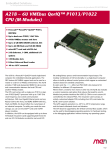
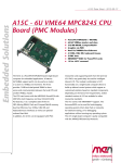
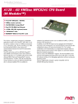
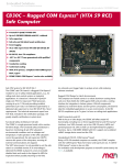
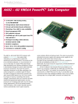
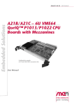
A21C Data Sheet - 2012-07-31
Embedded Solutions
A21C - 6U VMEbus QorIQ™
P1013/P1022 CPU (PMC/XMC)
n
n
n
n
n
n
n
n
n
n
The A21C is a Freescale™ QorIQ™ based single-board
computer for embedded industrial applications. The
SBC features full VME64 support and can be used as a
master or a slave in a VMEbus environment. The A21C
provides 1 MB local dual-ported SRAM for slave
access and communication between the local CPU and
another VMEbus master.
The CPU card comes with a single-core P1013 or dualcore P1022 QorIQ™ processor with up to 1.067 GHz
clock frequency and a serial communication
architecture. With two Gigabit Ethernet ports and one
RS232 COM at the front, and DDR3 SDRAM with ECC,
Flash and FRAM, the board offers the crucial basics
of an industrial computer. To satisfy your needs
for mass storage, you can use microSD™ cards and
mSATA plug-in modules.
In addition, the A21C can be equipped with up to two
XMC or PMC mezzanine cards on shared sites, providing
both front I/O (XMC/PMC) and rear I/O (PMC) for
functions such as graphics, mass storage, or further
Ethernet. The two PMC slots support modules up to 64bit/133-MHz PCI-X, while the XMC slots are powered by
1
Freescale™ PowerPC® QorIQ™ P1013, 800 MHz
Up to dual-core P1022, 1.067 GHz
64-bit VMEbus master and slave
Up to 2 GB DDR3 DRAM soldered, ECC
Up to 64 MB Flash and 128 KB FRAM
microSD™ card and mSATA slot
2 Gb Ethernet, 1 COM, additional I/O options
2 PMC/XMC slots
U-Boot Universal Boot Loader
-40 to +85°C screened
two PCI Express® x1 links each. The modular
combination of I/O functionality on a single-board
computer allows to build up tailored control systems
which appear as customized solutions based on standard
components.
Its sister card, the A21B, offers three M-Module™
slots instead of XMC/PMC, which are ideal for process
I/O requirements.
Where there's a need for even more or other I/O, the
A21C also includes a custom mezzanine-card option that
reduces the board by one PMC/XMC slot but provides
interfaces like USB 2.0, COM or even custom I/O
controlled by the onboard FPGA. The mezzanine card is
always an entirely customized adapter PCB, including
front I/O, and makes the A21C a semi-custom solution.
The A21C supports operation in a -40°C to +85°C
temperature range, and the board withstands shock and
vibration.
The CPU board is supported by the U-Boot Universal
Boot Loader, which can be used for bootstrapping
operating systems, for hardware testing, or for
debugging applications without running any operating
system.
®
A21C Data Sheet - 2012-07-31
Embedded Solutions
Technical Data
CPU
n Freescale™ QorIQ™ P1022 or P1013, dual or single core
o 600 MHz, 800 MHz or 1.067 GHz
o Two/one high-performance Power Architecture e500v2
cores
o Double precision floating point support and signal
processing engine (SPE) APU
Memory
n 32 KB L1 instruction cache and 32 KB L1 data cache per
processor core
n 256 KB L2 cache with ECC
n Up to 2 GB SDRAM system memory
o Soldered
o DDR3 with ECC support
o 333 MHz memory bus clock frequency (667 MT/s, 5.33
GB/s data rate)
n Up to 64 MB boot/program Flash
n 128 KB non-volatile FRAM
n Serial EEPROM 4 kbits for factory settings
Mass Storage
n microSD™ card slot
o Directly accessible on the board
o Connected to SDHC controller
n mSATA disk slot
o Directly accessible on the board (via small adapter
card)
o Connected via one SATA channel
I/O
n Ethernet
o Two 10/100/1000Base-T Ethernet channels at the front
o RJ45 connectors at front panel
o Two front LEDs for each port to signal LAN link and
activity status
n One RS232 UART (COM1)
o RJ45 connector at front panel
o Data rates up to 230.4 kbit/s
o 16-byte transmit/receive buffer
o Handshake lines: CTS, RTS
Front Connections
n Two Ethernet (RJ45)
n One RS232 COM (RJ45)
n PMC / XMC front I/O if populated
Rear I/O
n PMC 0 and 1
2
Mezzanine Extensions
n Two slots usable for PMC or XMC
n XMC slots
o Compliant with XMC standard VITA 42.3-2006
o Two x1 PCI Express® links for slot 0, data rate 250
MB/s per link in each direction (2.5 Gbit/s per lane)
o Two x1 PCI Express® links for slot 1, data rate 125
MB/s per link in each direction (1.25 Gbit/s per lane)
o PCIe® 1.0a support (PCI Express® Base Specification)
n PMC slots
o Compliant with PMC standard IEEE 1386.1
o PCI / PCI-X 32/64 bits, 33/66/133 MHz, 3.3 V V(I/O)
o PMC I/O module (PIM) support through J4 for both slots
Miscellaneous
n Real-time clock, buffered by a GoldCap or battery
(optional)
n Watchdog
n Voltage monitor and temperature sensor
n Reset button and status LEDs at the front panel
VMEbus
n Compliant with VME64 Specification
n Slot-1 function with auto-detection
n Master
o D08(EO):D16:D32:D64:A16:A24:A32:ADO:BLT:RMW
n Slave
o D08(EO):D16:D32:D64:A16:A24:A32:BLT:RMW
n 1 MB shared fast SRAM
n DMA
n Mailbox functionality
n Interrupter D08(O):I(7-1):ROAK
n Interrupt handler D08(O):IH(7-1)
n Single level 3 fair requester
n Single level 3 arbiter
n Bus timer
n Location Monitor
n Performance
o Coupled read/write D32 non-block transfer rate tbd.
MB/s
o DMA read/write D32 BLT transfer rate tbd. MB/s
o DMA read/write D64 MBLT transfer rate tbd. MB/s
Electrical Specifications
n Supply voltage/power consumption:
o +5 V (-3%/+5%), tbd. typ.
o +3.3 V (-3%/+5%), tbd. typ.
o ±12 V (-5%/+5%), only provided for mezzanines that
need 12 V
®
A21C Data Sheet - 2012-07-31
Embedded Solutions
Technical Data
Mechanical Specifications
n Dimensions: standard double Eurocard, 233.3 mm x 160 mm
n Weight (without mezzanines): 412 g
Environmental Specifications
n Temperature range (operation):
o -40..+85°C (screened)
o Airflow: min. 1.0 m/s
n Temperature range (storage): -40..+85°C
n Relative humidity (operation): max. 95% non-condensing
n Relative humidity (storage): max. 95% non-condensing
n Altitude: -300 m to +3000 m
n Shock: 50 m/s², 30 ms (EN 61373)
n Vibration (function): 1 m/s², 5 Hz - 150 Hz (EN 61373)
n Vibration (lifetime): 7.9 m/s², 5 Hz - 150 Hz (EN 61373)
n Conformal coating on request
MTBF
n 286 910 h @ 40°C according to IEC/TR 62380 (RDF 2000)
Safety
n PCB manufactured with a flammability rating of 94V-0 by
UL recognized manufacturers
EMC Conformity
n EN 55022 (radio disturbance)
n IEC 61000-4-2 (ESD)
n IEC 61000-4-3 (electromagnetic field immunity)
n
n
n
IEC 61000-4-4 (burst)
IEC 61000-4-5 (surge)
IEC 61000-4-6 (conducted disturbances)
BIOS
n U-Boot Universal Boot Loader
Software Support
n Linux (in preparation)
n VxWorks® (in preparation)
n OS-9® (in preparation)
n QNX® (on request)
n For more information on supported operating system
versions and drivers see Software.
3
®
A21C Data Sheet - 2012-07-31
Embedded Solutions
Diagram
4
®
A21C Data Sheet - 2012-07-31
Embedded Solutions
Configuration & Options
Standard Configurations
Article No.
CPU Type and
Clock
System RAM
Flash
FRAM
SATA
Mezzanine Slots Operating
Temperature
01A021C00
P1013 singlecore, 800 MHz
1 GB
32 MB
128 KB
Only mSATA
2 PMC/XMC
01A021B00
P1013 singlecore, 800 MHz
1 GB
32 MB
128 KB
Only mSATA
3 M-Modules™ -40..+85°C
-40..+85°C
Options
CPU
n QorIQ™ P1022 or P1013
o P1022: dual core
o P1013: single core
n All processors available with 600 MHz, 800 MHz or 1.067
GHz
Memory
n System RAM
o 1 GB or 2 GB
n Boot/program Flash
o 32 MB or 64 MB
n FRAM
o 0 KB or 128 KB
Miscellaneous
n Back-up battery holder for real-time clock (RTC)
(may be in mechanical conflict with PMC/XMC slot 0)
Software Support
n QNX®
Please note that some of these options may only be
available for large volumes. Please ask our sales staff
for more information.
Mass Storage
n Serial ATA (SATA)
o Onboard SATA connector for one additional port possible
o SATA Revision 2.x support
o Transfer rates up to 300 MB/s (3 Gbit/s)
o For connection of an in-system hard-disk drive
I/O
n Various additional I/O possible using onboard mezzanine
card
o Partly fixed set of interfaces, plus 16 pins for
custom I/O
o One USB 2.0 port, EHCI implementation
o Additional UART COM interface
o Display interface
o Custom I/O functions can be implemented as FPGA IP
cores (16 pins usable)
o Occupies the space of PMC/XMC slot 1
o Please note that the mezzanine card is always
completely customized, including front I/O, no
standard cards are available.
Mezzanine Slots
n 3 M-Modules™ instead of PMC/XMC (A21B variety)
5
®
A21C Data Sheet - 2012-07-31
Embedded Solutions
Ordering Information
Standard A21C Models
01A021C00
A21C, Freescale™ QorIQ™ single-core P1013,
800 MHz, 1 GB DDR3 ECC SDRAM, 32 MB Flash,
2 PMC/XMC slots, -40 to +85°C screened
Related Hardware
01A021B00
A21B, Freescale™ QorIQ™ single-core P1013,
800 MHz, 1 GB DDR3 ECC SDRAM, 32 MB Flash,
3 M-Module™ slots, -40 to +85°C screened
Memory
0751-0046
MicroSD card, 2 GB, -40..+85°C
0751-0051
SSD mSATA, 8 GB, -40..+85°C
0751-0052
MicroSD card, 4 GB, -40..+85°C
Miscellaneous Accessories
05F006-00
RS232 interface cable RJ45 to 9-pin D-Sub
(1 COM to 1 COM), 2m
05P000-01
25 mounting screw sets to fix PMC/XMC
modules on carrier boards
Software: Firmware/BIOS
This product uses the U-Boot bootloader available from
DENX together with board-specific additions from MEN.
14A021-00
U-Boot Bootloader (DENX/MEN) for A21B and
A21C
For operating systems not mentioned here contact MEN
sales.
Documentation
Compare Chart 6U VMEbus CPU and I/O cards Download
20A021-00
A21B/A21C User Manual
For the most up-to-date ordering information and direct
links to other data sheets and downloads, see the A21C
online data sheet under » www.men.de.
6
®
A21C Data Sheet - 2012-07-31
Embedded Solutions
Contact Information
Germany
MEN Mikro Elektronik GmbH
Neuwieder Straße 3-7
90411 Nuremberg
Phone +49-911-99 33 5-0
Fax +49-911-99 33 5-901
E-mail [email protected]
www.men.de
France
MEN Mikro Elektronik SA
18, rue René Cassin
ZA de la Châtelaine
74240 Gaillard
Phone +33 (0) 450-955-312
Fax +33 (0) 450-955-211
E-mail [email protected]
www.men-france.fr
USA
MEN Micro, Inc.
24 North Main Street
Ambler, PA 19002
Phone (215) 542-9575
Fax (215) 542-9577
E-mail [email protected]
www.menmicro.com
The date of issue stated in this data sheet refers to the Technical Data only. Changes in ordering information given herein do not affect the date of issue.
All brand or product names are trademarks or registered trademarks of their respective holders.
MEN is not responsible for the results of any actions taken on the basis of information in the publication, nor for any error in or omission from the publication.
MEN expressly disclaims all and any liability and responsibility to any person, whether a reader of the publication or not, in respect of anything, and of the
consequences of anything, done or omitted to be done by any such person in reliance, whether wholly or partially, on the whole or any part of the contents of the publication.
The correct function of MEN products in mission-critical and life-critical applications is limited to the environmental specification given for each product in the technical
user manual.The correct function of MEN products under extended environmental conditions is limited to the individual requirement specification and subsequent
validation documents for each product for the applicable use case and has to be agreed upon in writing by MEN and the customer.Should the customer purchase or use
MEN products for any unintended or unauthorized application, the customer shall indemnify and hold MEN and its officers, employees, subsidiaries, affiliates, and distributors
harmless against all claims, costs, damages, and expenses, and reasonable attorney fees arising out of, directly or indirectly, any claim or personal injury or death associated
with such unintended or unauthorized use, even if such claim alleges that MEN was negligent regarding the design or manufacture of the part.
In no case is MEN liable for the correct function of the technical installation where MEN products are a part of.
Copyright © 2012 MEN Mikro Elektronik GmbH. All rights reserved.
7
®