1
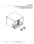
Plano de Emergência Individual
Bloco FZA-M-90
Bacia da Foz do Amazonas
ANEXO D
ANEXO D – DADOS DO SISTEMA DE TECNOLOGIA INOVADORA
Rev.00
Junho/2015
Page/side 1 of/av 1
NOFI Document no. / Dokumentnr.:
L650 - F - 500
NOFI Document name / Dokumentnavn:
NOFI Current Buster® 6 Pat.
DATASHEET (see also drawing L650-A-102)
B
A
02.01.12
20.05.11
Updated with weigt and storage volum
Preliminary. For information only.
Revision
Revisjon
Date (d,m,y)
Dato (d,m,å)
Issued for
Utgitt for
øw
dn
dn
By
Av
Checked
Sjekket
Approved
Godkjent
TECHNICAL DATA
Dimensions:
Storage weight (dry):
Storage volume on boom reel:
Front Opening(Swath):
Separator tank:
Flotation/cross beams:
All external fabric :
Material buoyancy chambers:
Mooring and lifting points:
Retrieval line at the stern:
Reflective markings:
Documentation:
Freeboard: Separator tank: Ø 1000/800mm, guide booms: Ø 800/600mm
Length: 62,9m
Width: 4,6m
Maximum Depth during operation: Ca. 2,6m
Total: 2017kg. Sweep and guide booms: 872 kg Separator: 1145 kg
Min. 10m³
34m
Gross volume 65m³, Net ca. 35m³ oil. Separation system is based on gravity
separation. In large spills the oil thickness will be min. 1m.
33 independent air chambers and 6 air filled cross beams with valve type MONSUN
XII.2.
Heavy Duty PU/PVC-coated polyester, 1150g/m²,
tensile strength 7400 N/50mm, tear strength min.1900 N.
Airtight PU/PVC blend coated polyester, 1150g/m²
8 off, evenly distributed around the system.
4 fastening points, split link connection to the retrieval line.
50x200mm reflective pads distributed around the system. On the in and outside.
Complete user documentation, L650-K-610
OPERATIONAL DATA
Area of use:
Oil types:
Towing /operational speed:
Debris collection system:
Temporary Oil storage:
Inflation:
Deployment:
Retrieval:
Adjustments during
operation:
Skimmer Interface:
Storage:
Storage and operating temp.:
Offshore and open coast up to Beaufort 5. Protected inlets, fjords, sounds and
harbours in extreme weather up to wind Beaufort 7. Also any strong current exposed
area with sufficient depth.
All types from diesel to high viscosity oil, ca. 5 – 180000cPS.
Effective collecting, concentrating and separating oil: Min. towing speed: 0,1-0,5
knots, Calm water: 5 knots, When towing directly against short period waves the
max. speed gradually decrease when wave height increase.
Prevents debris from entering the Pumping area.
The integrated non return valve enables the separator tank to be used for temporary
storage of recovered oil. HOLD for verification.
By backpack blower or electric/hydraulic fan through Monsun XII.2 valves
Deployment with guidebooms or separator tank first. An area with minimum width of
5m and length of 5m is recommended in front of the boom reel. Deployment time
from reel ca. 25 minutes if two fans are available.
The NCB6 can be retrieved with guidebooms or separator tank first. Retrieval time
ca. 30 minutes.
The system is designed for operation without any adjustments required even if the
speed and oil types vary.
Within the operational limits, the oil thickness in the separator is high with no current
or vortex. Almost all types of skimmers and pumps may be used efficiently in the
separator with low water content of recovered oil.
On boomreel with shaft diameter of minimum 500mm. Turntable recommended for
easier retrieval.
-35 to +70°C (-13 to 158 °F)
Subject to contractual terms to the contrary, this document and its content are the property of NOFI Tromsø AS and may not be reproduced or shown to any third party without
our prior written approval. Dette dokumentet er NOFI Tromsø AS sin eiendom og skal ikke kopieres eller vises tredjeperson uten vår skriftlige forhåndsgodkjennelse
Page/side 1 of/av 16
Document Name / Dokumentnavn:
NOFI Current Bustery 6
Pat.
User’s manual
NOFI Document no. / Dokumentnr.:
L650 - M - 640
A
02.04.12
Comments
Revision
Revisjon
Date (d,m,y)
Dato (d,m,å)
Issued for
Utgitt for
By
Av
Checked
Sjekket
Approved
Godkjent
Subject to contractual terms to the contrary, this document and its content are the property of NOFI Tromsø AS and may not be reproduced or shown to any third party without our prior written approval.
Om ikke annet er avtalt i kontraktsbetingelser er dette dokumentet NOFI Tromsø AS sin eiendom og skal ikke kopieres eller vises tredjeperson uten vår skriftlige forhåndsgodkjennelse.
Doc. no./ Dok. nr. L650-M-640
Rev.: A
Doc. name/Dok. navn: NOFI Current Bustery 6 Pat.
Page/side 2 of/av 16
User’s Manual
TABLE OF CONTENTS
0 GENERAL ............................................................................................................................................................... 3
1 SYSTEM DESCRIPTION ........................................................................................................................................ 3
General .............................................................................................................................................................. 3
NOFI Current Buster 6 ....................................................................................................................................... 4
Pat.Pend
High speed Otter
Guidebooms ................................................................................................................ 4
Sweep ................................................................................................................................................................ 4
Collector area .................................................................................................................................................... 4
Tapered Channel Skimming Device .................................................................................................................. 5
Separator and storage tank ............................................................................................................................... 5
Water Drainage Valves ...................................................................................................................................... 5
Towlines and retrieval line ................................................................................................................................. 5
CONSTRUCTION ....................................................................................................................................................... 6
Outer fabric ........................................................................................................................................................ 6
Air Chambers ..................................................................................................................................................... 6
Crossbeams ...................................................................................................................................................... 7
Debris collection and wave dampening system ................................................................................................ 7
Wave dampening feature and splash over protection in the stern .................................................................... 7
Transportation and decon detachment and assembly point (TDDAP) .............................................................. 8
Oil stopping Device ............................................................................................................................................ 8
Tie off loops ....................................................................................................................................................... 8
Retrieval bridle ................................................................................................................................................... 8
Valves ................................................................................................................................................................ 8
Reflective areas ................................................................................................................................................. 8
Highlighted areas ............................................................................................................................................... 9
Pump area ......................................................................................................................................................... 9
2 STORAGE, DEPLOYMENT AND RETRIEVAL ...................................................................................................10
Storage ...........................................................................................................................................................10
Deployment .....................................................................................................................................................10
Inflation ...........................................................................................................................................................10
RETRIEVAL ...........................................................................................................................................................11
Retrieving with Guidebooms first ....................................................................................................................11
Retrieving with Separator tank first .................................................................................................................11
3 OPERATION ........................................................................................................................................................12
Two boats towing, one boat pumping .............................................................................................................12
Tow forces ......................................................................................................................................................12
Filling the Separator tank ................................................................................................................................12
Adjustment ......................................................................................................................................................13
Maximum towing speed ..................................................................................................................................13
Towing backwards is not recommended .........................................................................................................13
Transportation speed ......................................................................................................................................13
Type of oil .......................................................................................................................................................13
Re-inflation of air chambers ............................................................................................................................13
Pumps and skimmers .....................................................................................................................................14
Pumping and offloading recovered oil .............................................................................................................14
Turning the Current Buster system .................................................................................................................15
Removal of debris ...........................................................................................................................................15
Towing configuration .......................................................................................................................................16
Small Spills .....................................................................................................................................................16
Subject to contractual terms to the contrary, this document and its content are the property of NOFI Tromsø AS and may not be reproduced or shown to any third party without our prior written approval.
Om ikke annet er avtalt i kontraktsbetingelser er dette dokumentet NOFI Tromsø AS sin eiendom og skal ikke kopieres eller vises tredjeperson uten vår skriftlige forhåndsgodkjennelse.
Rev.: A
Doc. no./ Dok. nr. L650-M-640
Doc. name/Dok. navn: NOFI Current Bustery 6 Pat.
Page/side 3 of/av 16
User’s Manual
0 GENERAL
Pat.
This manual describes the use of the NOFI Current Bustery 6
.
The NOFI Current Buster 6 (NCB6) is the latest product based on the CURRENT BUSTER TECHNOLOGY.
Some of the pictures in this manual show other NOFI Current Buster systems.
All fabrics are vulnerable to damage when dragged over sharp edges, rough concrete and asphalt etc. Such
surfaces and sharp edges must be covered with tarpaulin or similar.
After use in oil the equipment should be cleaned as soon as possible, see General Cleaning Procedure for oil
booms and PVC/PU fabrics, doc. no. F000-N-680, and NOFI Current Buster Cleaning Guide,
doc. no. L600-N-682.
Pat.
NOTE: The NOFI Current Bustery 6
is a contingency boom and is not designed for permanent anchoring.
During outdoor storage the equipment must be covered with a tarpaulin to avoid damage from sunlight. If stored
in a closed container etc. proper ventilation should be provided to prevent growth of micro-organisms.
SAFETY : Any boom handling and especially high speed operations involve heavy forces and impose a
safety ri sk. In order to avoid personnel injuries, sound seamanship should be practised in all operations.
Local sa fety regulations and practice must be followed.
1 SYSTEM DESCRIPTION
General
Pat.
The NOFI Current Bustery 6 is designed to collect, separate and contain oil at speeds ranging from 0,5 up to
5 knots in reasonable weather conditions.
Results from testing the NOFI Current Buster 4, in OHMSETT test tank, indicate that the system will normally
contain 65% to 98% of the oil, depending on speed, type of oil and wave conditions.
The system is generally delivered with towlines and retrieval line. Guidebooms and sweep are integrated in the
NOFI Current Buster 6 system. For more information, see Data Sheet, doc. no. L650-F-500.
Fig. 1: NOFI Current Bustery 6Pat.
Subject to contractual terms to the contrary, this document and its content are the property of NOFI Tromsø AS and may not be reproduced or shown to any third party without our prior written approval.
Om ikke annet er avtalt i kontraktsbetingelser er dette dokumentet NOFI Tromsø AS sin eiendom og skal ikke kopieres eller vises tredjeperson uten vår skriftlige forhåndsgodkjennelse.
Rev.: A
Doc. no./ Dok. nr. L650-M-640
Doc. name/Dok. navn: NOFI Current Bustery 6 Pat.
Page/side 4 of/av 16
User’s Manual
NOFI Current Buster 6
The NOFI Current Buster 6 system is supplied as a complete unit, and consists of 5 main parts:
Pat.Pend
1. High speed Otter
guideboom
2. Sweep
3. Collector area
4. Tapered channel skimming device
5. Separator and storage tank
See drawing no. L650-A-104 for details and dimensions.
Fig. 2: NOFI Current Buster 6 at ca. 4 knot towing speed
Pat.Pend
High speed Otter
Guidebooms
The integrated Otter guidebooms are optimised to give a larger front opening compared to a conventional oil
boom.
Fig. 3: Integrated high speed OtterPat.Pend guideboom
Sweep
®
The integrated Sweep is based on NOFI VEE-SWEEP technology, with open apex.
Fig. 4: Integrated sweep
Collector area
The collector area is located at the stern part of the “V”-shaped sweep. The main purpose of the collector area is
to create optimal flow conditions into the tapered channel skimming device.
Fig. 5: Position of the collector area
Subject to contractual terms to the contrary, this document and its content are the property of NOFI Tromsø AS and may not be reproduced or shown to any third party without our prior written approval.
Om ikke annet er avtalt i kontraktsbetingelser er dette dokumentet NOFI Tromsø AS sin eiendom og skal ikke kopieres eller vises tredjeperson uten vår skriftlige forhåndsgodkjennelse.
Rev.: A
Doc. no./ Dok. nr. L650-M-640
Doc. name/Dok. navn: NOFI Current Bustery 6 Pat.
Page/side 5 of/av 16
User’s Manual
Tapered Channel Skimming Device
The main purpose of the Tapered Channel Skimming Device is to lift the upper layer of the water containing the
oil into the separator, while draining most of the surplus water under the system.
Fig. 6: Position of the tapered channel skimming device
Separator and storage tank
The oil and water mixture entering the separator is separated by gravity separation (settling). The large volume of
the separator ensures sufficient separation time so the oil is effectively separated from the seawater. Surplus
water is drained through valves in the bottom of the separator. During operation, even at high speeds, the oil is
calm in a thick layer inside the separator, and consequently optimal pumping conditions are achieved.
Fig. 7: Position of the separator
Water Drainage Valves
The drainage valves are distributed in the bottom of the separator tank. Overpressure in the separator tank
causes the valves to open and let out excess water.
Towlines and retrieval line
Normally two 50 m towlines and two 4 m tow bridles are supplied with the system. Tow bridle and towline can be
disconnected.
Tow Bridle
Towline
Fig.8: Towline and tow bridle
A retrieval line is connected to the stern of the NOFI Current Buster 6. The line may be connected or
disconnected near the stern of the NOFI Current Buster 6 with a quick link (G-Hook).
20mm retieval
line. Min break
load 6600kg
G-hook quick
connection
Float
Retrieval bridle
Fig.9: Retrieval line
Subject to contractual terms to the contrary, this document and its content are the property of NOFI Tromsø AS and may not be reproduced or shown to any third party without our prior written approval.
Om ikke annet er avtalt i kontraktsbetingelser er dette dokumentet NOFI Tromsø AS sin eiendom og skal ikke kopieres eller vises tredjeperson uten vår skriftlige forhåndsgodkjennelse.
Rev.: A
Doc. no./ Dok. nr. L650-M-640
Doc. name/Dok. navn: NOFI Current Bustery 6 Pat.
Page/side 6 of/av 16
User’s Manual
Construction
The NOFI Current Buster 6 is made as one unit except the Crossbeams (6 off) and may be divided in two for
transportation or decontamination purposes. The system consists of an outer fabric (Jacket) protecting the air
chambers.
Outer fabric
The outer fabric is folded over the air chambers and connected on top by plastic eyelets and cleats locked by a
plastic-covered rope, which may be disconnected during cleaning when the system is contaminated.
Outer fabric (Jacket)
Air chamber
Fig. 10: Outer fabric enclosing the air chambers
All loadbearing functions (mooring points, fastening points for the transverse bladders etc) are handled by the
outer fabric
NOTE: If the cleats are deformed by pressure or heat the original shape may be restored with the help of a hot air
gun.
Air Chambers
The NOFI Current Buster 6 has two air chamber systems. There is one in the Guide booms and one in the
Separator tank. The air chambers in the Guide booms are 18 individual chambers whereas the air chambers in
the separator area are connected to each other forming a frame work, called the Flotation frame.
Flotation frame
Individual air chambers
Connection between
air chambers
Crossbeams
The air filled Crossbeams add rigidity to the construction. In addition the Crossbeams located at the waterline in
the separator have a wave dampening effect, reducing the waves coming into the separator. The Crossbeams
may be removed for cleaning etc. and are correctly positioned by number codes on the Crossbeams that
correspond with the code on the outer fabric. Note that the fastening straps on Crossbeam no. 1 and 2 are
crossed as shown in the picture (see Fig. 11)
Subject to contractual terms to the contrary, this document and its content are the property of NOFI Tromsø AS and may not be reproduced or shown to any third party without our prior written approval.
Om ikke annet er avtalt i kontraktsbetingelser er dette dokumentet NOFI Tromsø AS sin eiendom og skal ikke kopieres eller vises tredjeperson uten vår skriftlige forhåndsgodkjennelse.
Rev.: A
Doc. no./ Dok. nr. L650-M-640
Doc. name/Dok. navn: NOFI Current Bustery 6 Pat.
6
5 4 3
2
1
Page/side 7 of/av 16
User’s Manual
Fig. 11: Crossbeams, 6 off
Fig. 12: Crossbeams with number coding. The crossed fastening straps only applies
to Crossbeam 1 and 2.
Debris collection and wave dampening system
In connection with crossbeam no. 3 and no. 4 there are curtains that have the purpose to prevent debris from
entering the Pump area. The curtains also act as a wave dampening system that reduces internal movement of
oil and water content in the Separator tank.
Wave dampening feature and splash over protection in the stern
The purpose of the perforated fabric in the stern of the Separator and storage tank, see fig. 13, is to reduce
splash over and reduce wave activity in rough weather conditions and in waves. The device also adds rigidity to
the system.
Fig. 13: Splash over protection/wave dampening system in the stern.
Subject to contractual terms to the contrary, this document and its content are the property of NOFI Tromsø AS and may not be reproduced or shown to any third party without our prior written approval.
Om ikke annet er avtalt i kontraktsbetingelser er dette dokumentet NOFI Tromsø AS sin eiendom og skal ikke kopieres eller vises tredjeperson uten vår skriftlige forhåndsgodkjennelse.
Rev.: A
Doc. no./ Dok. nr. L650-M-640
Doc. name/Dok. navn: NOFI Current Bustery 6 Pat.
Page/side 8 of/av 16
User’s Manual
Transportation and decon detachment and assembly point (TDDAP)
The connection between the Buster Separator Tank and the integrated sweep and guide boom is a
Transportation and decon detachment and assembly point (TDDAP). This includes a connection of the collector
area net bottom section to the collector area skirt.
Fig. 14: TDDAP
Oil stopping Device
This device is positioned at the end of the tapered channel towards the stern. During oil collection and operation
the device will lay down in open position allowing oil to enter the separator tank. If the NCB6 system for any
reason has to stop the device will go into closed position preventing the collected oil to escape.
Tie off loops
Nine tie off loops made in heavy duty webbing and abrasion reinforced fire hose are distributed along the entire
NOFI Current Buster 6, see fig. 15.
Loop 9
Loop 6
Loop 7
Loop 8
Loop 5
Loop 2
Loop 4
Loop 3
Loop 1
Fig. 15: Tie off loops
The tie off loops indicated on Fig.15 are intended for heavy duty use e.g. towing of other devices, lifting etc.
NOTE: Other potential tie off loops or similar must not be used for any fastening, including the closing wire on
top of the freeboard or line on the valve lid. The only exception is fastening of small objects such as radar
reflectors or marking lights.
Retrieval bridle
At the stern of the separator there is a retrieval bridle made of heavy duty webbing and rope. The bridle may be
temporarily dropped into the separator if there is any chance of the bridle interfering with propellers on vessels
located alongside.
Valves
The air chambers are equipped with valves of type Monsun XII.2 for filling and evacuation of air. All air chambers
including the cross beams are equipped with 2 off valves, one in each end. For contamination protection the
valve has a screw cap that is secured to the valve with a cord.
Reflective areas
Reflective areas are situated under each valve and opposite area on the inside on the system see, fig. 16.
Fig. 16: Reflective area
Subject to contractual terms to the contrary, this document and its content are the property of NOFI Tromsø AS and may not be reproduced or shown to any third party without our prior written approval.
Om ikke annet er avtalt i kontraktsbetingelser er dette dokumentet NOFI Tromsø AS sin eiendom og skal ikke kopieres eller vises tredjeperson uten vår skriftlige forhåndsgodkjennelse.
Rev.: A
Doc. no./ Dok. nr. L650-M-640
Doc. name/Dok. navn: NOFI Current Bustery 6 Pat.
Page/side 9 of/av 16
User’s Manual
Highlighted areas
The NCB6 systems have three areas that are highlighted with text. This is information for utility vessels and about
areas on the boom that can affect their operation.
The front ends of the Guide booms has text both on the in- and on outside. Outside text states system Starboard
and Portside. The inside text, Front rope, states that there is a rope connected between Port and Starboard guide
boom. The start of the net section is marked with text and a directional arrow.
Fig. 17: Starboard
Fig. 19: Net section
Fig. 18: Front rope
Pump area
The dedicated area 3 x 3 m set of for pumping and skimming is Orange in contrast to the rest of the system which
is Yellow. “Pump Area” is specified in black letters on the orange areas.
Fig. 20: 3 x 3 m Pump area in the Separator
Subject to contractual terms to the contrary, this document and its content are the property of NOFI Tromsø AS and may not be reproduced or shown to any third party without our prior written approval.
Om ikke annet er avtalt i kontraktsbetingelser er dette dokumentet NOFI Tromsø AS sin eiendom og skal ikke kopieres eller vises tredjeperson uten vår skriftlige forhåndsgodkjennelse.
Rev.: A
Doc. no./ Dok. nr. L650-M-640
Doc. name/Dok. navn: NOFI Current Bustery 6 Pat.
Page/side 10 of/av 16
User’s Manual
2STORAGE, DEPLOYMENT AND RETRIEVAL
Storage
The NOFI Current Buster 6 system can be stored in a custom made storage container, on a pallet or on a boom
reel. The inner diameter of the reel should be at least 500 mm in order to avoid damage to the valves.
Fig. 21: NOFI Current Buster 6 stored on a
10m 3 boom reel
Deployment
The NOFI Current Buster 6 is designed for deployment with guidebooms or separator tank first.
An area with minimum width of 5m and length of 5m is recommended in front of the boom reel. Deployment time
from reel is approx. 25 minutes if two fans are available.
The integrated Sweep net is weighted and will sink. When deploying in shallow water the net may snag on the
bottom. In such unfavourable conditions a rope may be tied around the sweep arms and the netting to prevent the
net from sinking. NOTE: This rope must be cut or removed prior to operation.
Inflation
Inflation is normally done by a backpack type fan. Electric and hydraulic fans may also be used. To save time, two
fans are recommended, one on each side, during deployment.
The air chamber is pressurised to maximum level of a backpack fan, approximately 100 mbar.
CAUTION: The use pressure air for inflation is not
recommended due to danger for overpressure and
rupture causing personal injury. If for any reason
pressure air without pressure gauge is used, the
following guidelines may be followed for correct
pressure:
At 50-100 mbar a normal person may press a knee 510 cm down or a thumb 2-4 cm down in the air
chamber, see pictures.
5 - 10 cm
2 - 4 cm
Fig. 22: Testing the overpressure by depressing the air chamber
with a knee (left) or a thumb (right).
The Monsun XII.2 valves have an open and a closed position. W hen the valve seat (plate) is pressed down and
turned to the right the valve is locked in open position (as is done during retrieval). When turning to the left the
valve is closed. It is still possible to perform inflation with the valve in closed position, since the air pressure
presses down the spring activated valve seat, thus letting air in.
Subject to contractual terms to the contrary, this document and its content are the property of NOFI Tromsø AS and may not be reproduced or shown to any third party without our prior written approval.
Om ikke annet er avtalt i kontraktsbetingelser er dette dokumentet NOFI Tromsø AS sin eiendom og skal ikke kopieres eller vises tredjeperson uten vår skriftlige forhåndsgodkjennelse.
Rev.: A
Doc. no./ Dok. nr. L650-M-640
Doc. name/Dok. navn: NOFI Current Bustery 6 Pat.
Page/side 11 of/av 16
User’s Manual
SAFETY: If the screw cap isn’t attached oil may enter the valve and oil may splash into your face and eyes the
next time the valve is opened.
Screw cap
Valve seat
Fig. 23: Monsun XII.2 valve (left) with screw cap (right)
shown in open position. The valve seat (plate) in the middle
of the valve has been pressed down and turned right.
Valve
In orde r to attain sufficient pressure in the air chambers, inflation must be performed with the valve plate in
closed position. Let the fan run at full speed until the inflation hose nozzle has been pulled out of the valve. The
spring-activated valve closes automatically and no air pressure is lost during opening and closing of the valves.
All air chambers have two valves. The purpose is to make it easy to inflate/deflate the NOFI Current Buster 6
where the space is limited. Prior to inflation make sure that the opposite valve is closed. Corresponding
valves have the same colour coding.
Retrieval
The Current Buster 6 system is designed to be retrieved in both directions with separator or guidebooms first.
Retrieving with Guidebooms first
Retrieving with the Guidebooms first has not been tested thoroughly and should be performed with caution.
Each user should develop their own strategy for this operation.
IMPORTANT NOTE: When retrieving the NOFI Current Buster 6 with guidebooms first it takes time before the
water in the separator is drained out through the Drainage valves. This must be done gradually, lifting inch by
inch, without applying too much force.
Retrieving with Separator tank first
A retrieval line, 50m, is connected to the retrieval bridle by a G-Hook (splitlink) connection (see Fig. 24).
The line has a minimum breaking load of 6600kg and is the weak-link during retrieval. Retrieval time ca. 30
minutes.
20mm retieval
line. Min break
load 6600kg
G-hook quick
connection
Float
Retrieval bridle
Fig. 24: Retrieval line with G-hooks
IMPORTANT NOTE: When retrieving the NOFI Current Buster 6 it takes some time before the separator is
emptied since the water has to flow over the oil stopping device and through the tapered channel and the narrow
water outlet in the separator. This must be done gradually, lifting inch by inch, without applying too much force. In
unfavourable conditions water pockets may be formed, requiring manual intervention.
If the system is retrieved to a boom reel, it must be wound up firmly. A vessel or a vehicle may assist in
maintaining tension in the system while it is being retrieved. When winding up the towlines, one should make sure
that the towlines do not get stuck in between the boom reel’s sidewalls and the boom system itself, due to risk of
jamming the towlines.
Subject to contractual terms to the contrary, this document and its content are the property of NOFI Tromsø AS and may not be reproduced or shown to any third party without our prior written approval.
Om ikke annet er avtalt i kontraktsbetingelser er dette dokumentet NOFI Tromsø AS sin eiendom og skal ikke kopieres eller vises tredjeperson uten vår skriftlige forhåndsgodkjennelse.
Rev.: A
Doc. no./ Dok. nr. L650-M-640
Doc. name/Dok. navn: NOFI Current Bustery 6 Pat.
Page/side 12 of/av 16
User’s Manual
3 OPERATION
The NOFI Current Buster 6 system is a rather new concept and this manual does not describe optimal operation
with all types of vessels/equipment or all modes of operation. Each user should develop their own standard
operational procedure based on their own needs.
Single vessel operation
NOFI Current Buster 6 has been tested with a single boat and BoomVane. The test was performed with a
standard BoomVane and gave a sweep width of ca.18m.
Type and size of towboat
The towboats should be of a type that has good directional stability and in other ways are suitable to tow objects.
Two boats towing, one boat pumping
Fig.s 25 and 26 show the system being towed by the help of 2 towboats.
Fig. 25: Two boats tow the system. A skimming vessel is moored
alongside the separator while towing.
Fig. 26: NOFI Current Buster 6 in a two boat configuration
during testing in Tromsø.
Tow forces
Measurements performed during testing has indicated approximate tow forces:
At 3 knots the tow force was measured to approx.1,8 tons per vessel, and at 5 knots about 3 tons per vessel.
The values apply for straightforward movement with even speed in calm sea. In case of sudden changes in speed
or direction, and in choppy sea, larger tow forces must be expected.
Filling the Separator tank
When the towing starts, the separator will gradually fill with water. An initiate speed of ca. 2,5 - 5 knots is
recommended in order to fill up the separator. The filling process takes approx. 10-15 minutes depending on
towing speed. During this process the separator bottom may appear unstable but the system will still collect oil.
If the towing stops, ballast in the separator will impede the separator bottom from floating up. However, some
water may escape, and when the towing begins again it will take a few minutes to reach the normal filling level.
Subject to contractual terms to the contrary, this document and its content are the property of NOFI Tromsø AS and may not be reproduced or shown to any third party without our prior written approval.
Om ikke annet er avtalt i kontraktsbetingelser er dette dokumentet NOFI Tromsø AS sin eiendom og skal ikke kopieres eller vises tredjeperson uten vår skriftlige forhåndsgodkjennelse.
Rev.: A
Doc. no./ Dok. nr. L650-M-640
Doc. name/Dok. navn: NOFI Current Bustery 6 Pat.
Page/side 13 of/av 16
User’s Manual
Adjustment
Even if speed through the water and oil type vary no adjustments of the system are required.
Maximum towing speed
The maximum towing speed is determined in two ways:
1) The maximum oil collecting speed is 5 knots through water. Operation at higher speed is not recommended.
Note that in current exposed areas a GPS reading will give wrong speed reading against water.
2) When towing directly against short-period waves the speed should be limited to 3 knots. W hen splash over
occurs in the stern the speed must be further reduced as contained oil is lost.
Normally higher speeds may be used when towing with the waves or at 90 degrees to the wave direction,
compared to directly into the waves, see Fig. 27.
Waves and wind
Reduced speed
against waves
High speed
High speed
High speed
Fig. 27: Towing speed in relation to wind/waves
Towing backwards is not recommended
CAUTION: Towing the system backwards (except during retrieval at very low speed) is not recommended, as the
system is not designed for this and will be damaged.
Transportation speed
If the system needs to be transported rapidly from one location to another, actions should be made to decrease
the front opening of the system in order to reduce the amount of water entering the system.
This may be done by transferring both towlines to one vessel. Speed through water should still be limited to 6
knots.
Type of oil
The available information from tests conducted with oil indicates that the system can handle most types of oil from
low to high viscosities, including diesel oil. Some reports indicate that the system may even be efficient in
collecting blue shine.
Re-inflation of air chambers
If there are significant temperature variations (between night and day) or long operating periods the air chambers
may require re-inflation if they deflate or deform. This may be done with portable fans.
Subject to contractual terms to the contrary, this document and its content are the property of NOFI Tromsø AS and may not be reproduced or shown to any third party without our prior written approval.
Om ikke annet er avtalt i kontraktsbetingelser er dette dokumentet NOFI Tromsø AS sin eiendom og skal ikke kopieres eller vises tredjeperson uten vår skriftlige forhåndsgodkjennelse.
Rev.: A
Doc. no./ Dok. nr. L650-M-640
Doc. name/Dok. navn: NOFI Current Bustery 6 Pat.
Page/side 14 of/av 16
User’s Manual
Pumps and skimmers
The NCB6 system is capable of accumulating up to 1m of oil in the Separator. This should be taken in to
consideration when choosing what kind of offloading equipment to be used. Several types of pumps and
skimmers may be used for offloading the separator. The pump’s or skimmer’s outer surface must be free from
sharp edges or rotating parts, which may damage the fabric.
Pay attention to the pump and hoses so that no abrasion damage occur e.g. on top of the freeboard. If necessary
attach some abrasion protection, tarpaulin etc.
Fig. 28: A skimmer in the separator (Image of NOFI Current Buster 2)
Fig. 29: Rope mop skimmer operating in the separator(Image of
NOFI Current Buster 2)
Pumping and offloading recovered oil
The pumping vessel can be moored alongside the separator. In order to avoid damage to the system,
the pumping vessel should be of a reasonable size compared to the NOFI Current Buster 6, and not have sharp
edges or similar facing the system.
Connected
to towline
Pumping
vessel
Fig. 30: Pumping vessel moored alongside the separator with
mooring lines indicated.
Fig. 31: Mooring line from the bow of the pumping vessel to the
connection point between the sweep and the towline. (Image of NOFI
Current Buster 4)
Depending on available vessels and utility equipment there are several possible methods and strategies for
pumping of the Current Buster 6.
SAFETY: Make sure that the pumping vessel does not drift off during high-speed operation leading to the
skimmer snagging in the separator.
Subject to contractual terms to the contrary, this document and its content are the property of NOFI Tromsø AS and may not be reproduced or shown to any third party without our prior written approval.
Om ikke annet er avtalt i kontraktsbetingelser er dette dokumentet NOFI Tromsø AS sin eiendom og skal ikke kopieres eller vises tredjeperson uten vår skriftlige forhåndsgodkjennelse.
Rev.: A
Doc. no./ Dok. nr. L650-M-640
Doc. name/Dok. navn: NOFI Current Bustery 6 Pat.
Page/side 15 of/av 16
User’s Manual
Fig.32: Excavator with pump offloading
a NOFI Current Buster 8 during the
Macondo spill in 2010.
Turning the NOFI Current Buster system
If the two towboats are well coordinated, it is a simple task to turn the whole boom system. This can be done with
the pumping vessel moored alongside the separator.
Fig. 33: Turning the system at high towing speed (Image of NOFI
Current Buster 4)
Removal of debris
Logs, debris and sharp objects may enter the system and cause serious damage. If this occurs, stop the
operation and remove the debris.
Floating seaweed, kelp etc. may after a time clog the bottom net in the collector area, create an obstruction in the
tapered channel tunnel or clog the outlet of the separator.
Fig. 34: Tapered channel clogged by hawser
Subject to contractual terms to the contrary, this document and its content are the property of NOFI Tromsø AS and may not be reproduced or shown to any third party without our prior written approval.
Om ikke annet er avtalt i kontraktsbetingelser er dette dokumentet NOFI Tromsø AS sin eiendom og skal ikke kopieres eller vises tredjeperson uten vår skriftlige forhåndsgodkjennelse.
Rev.: A
Doc. no./ Dok. nr. L650-M-640
Doc. name/Dok. navn: NOFI Current Bustery 6 Pat.
Page/side 16 of/av 16
User’s Manual
If the clogging reduces the performance to an unacceptable level the foreign objects must be removed while the
towing is stopped.
Towing configuration
The following information should be handed over to the towboat captains prior to towing:
In order to maintain the correct towing formation when operating the NOFI Current Buster 6 the following rules
should be followed:
1) One towboat should lead and the other should follow and make necessary adjustments. Still both the
towboats are responsible for keeping the system in a good formation. Agree on who is the leader boat, draw
lots if necessary.
2) The towlines should have equal lengths and be moored as low as possible on the towboats.
3) Both towboats should continuously monitor the boom.
4) Start towing at 2,5 knots, the distance between the towboats small, e.g. 15-20 m.
5) The towboats should preferably move more or less in parallel.
6) The towboats should practice on changes in speed and course.
7) Gradually increase the distance between the towboats until correct formation is achieved, see Fig. 35.
8) If there are continuous problems with misshape of the boom the boats may move closer.
9) It is normally easier to keep the configuration of the system at a speed above 2 knots.
Move
forwar
d
Consider moving
closer together
Slow
down
Front rope
Correct configuration
of front rope
(rope not fully
stretched out)
Observe continuously
for any misshape of
the boom in these areas
and correct immediately
Misshape on Guideboom
FAULT THAT MUST
BE CORRECTED
Misshape on Sweep
FAULT THAT MUST
BE CORRECTED
Fig. 35: Correct positioning of towboats.
Fig. 36: Incorrect positioning of towboats causing misshape on guide
boom and sweep.
Small Spills
If the oil spill is small, i.e. less than the storage capacity of the separator (approx. 30-40 tonnes), two boats may
tow the system and the oil may be discharged at the end of the clean-up operation. Alternatively, a pumping
vessel may empty the separator as needed.
Subject to contractual terms to the contrary, this document and its content are the property of NOFI Tromsø AS and may not be reproduced or shown to any third party without our prior written approval.
Om ikke annet er avtalt i kontraktsbetingelser er dette dokumentet NOFI Tromsø AS sin eiendom og skal ikke kopieres eller vises tredjeperson uten vår skriftlige forhåndsgodkjennelse.