1
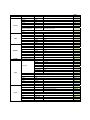
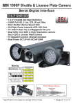
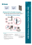
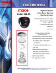
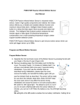
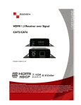
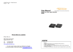
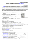
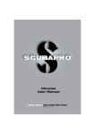
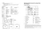
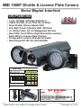
SDI 1080P Shuttle & License Plate Camera
Serial Digital Interface
CHLP120IR-SDI
• 1/2.8” COLOR SDI High Definition
• 1080P Full HD, 0 Lux, ICR, IR cut Filter.
• Slow Shutter (Sense Speed 32X)
• 224 High Power Intensity LED, 300 Feet.
• 10-120mm Auto Iris 2.0 Megapixels IR Lens
• Dual CDS, front CDS is High Resolution camera,
back CDS is License Plate Camera
• 10 dipswitch control, Bracket included
• Dual Power DC12V 4A /AC24V 60VA
Warning
ON SDI High Definition Camera The DIP Switch
NO.10
OFF License Plate Camera
ON
OFF
1 2 3 4 5 6 7 8 9 10
MENU LENS AUTO
EXP AIS SHUTTER
Shu tt er speed select
License Plate
0
OFF
1
A.FLK
20 Miles 30 KM
40 Miles 60 KM
2
1/160sec.
50 Miles 80 KM
3
1/250sec.
65 Miles 100 KM
4
1/500sec.
80 Miles 130 KM
5
1/700sec.
90 Miles 160 KM
6
1/1000sec.
110 Miles 180 KM
7
1/1600sec.
120 Miles 200 KM
8
1/2500sec.
140 Miles 230 KM
“IR On” Effective Distance
IR On
Normal Camera
300Feet
300Feet
* Specifications are subject to change without notice
100Feet
200Feet
100Feet
50Feet
0Feet
** Designed in U.S.A.
RS485 Housing Control
(Box camera)
User's Manual
Notice
To reduce the risk of electric shock, please do not disassemble by yourself, it
should be repaired by a qualified technician.
The lightning arrow symbol reminds users that there is
dangerous voltage nearby, enough for a body to produce an
electric shock and cause bodily harm.
The caution symbol, reminds users to pay close attention to the
relevant instructions during the operation and maintenance of
the product.
Please fill in the product model and manufacturing number. This information will
assist you in the future should you need to refer to it for service or repair.
Model:
Number:
Important Safety Precautions
1、Before installation, please read the manual, and keep this
guide for future reference.
2、Please comply with all warnings on the device and follow the
instructions carefully.
3、 Please wipe or clean the device before connecting the device
to power, and please do not use liquid/spray cleaning agents.
4、Please used our recommended factory parts when in need of
repair, otherwise, failure may occur.
5、The device should use the recommended power and voltage from
the manual. If the power and voltage of the installation site
is unclear, please contact us for further assistance.
6、 Protect the power cord, especially along the plug and camera
data lines. Do not submerge in water or any liquids.
7、 To prevent lightning surge damage, please install surge
protectors.
8、 To prevent fire and electric shock, please do not over-extend
the data lines or allow foreign substances into the machine which
may cause dangerous corrosion.
9、Do not install in areas that have unstable brackets, walls,
roofs, etc. Otherwise, it may result in bodily harm.
10、Please contact your dealer should you have the following
issues:
10.1 Wrong power supply or voltage.
10.2 Damaged housing unit.
10.3 Abnormal behavior with device performance.
10.4 After consulting the user manual and it still does not
operate.
11、When part replacement is needed, please contact your dealer
so we can provide approved parts to maintain the same
performance.
I Summary .............................................. 6
II Features ............................................ 6
III Product Size Chart ................................. 8
IV Socket Function .................................... 9
1.Camera control board layout ...................... 9
2.Power board socket diagram ....................... 10
V Connecting different camera models ................. 12
1、Color box camera with DC12V .................... 12
2、Color box camera with AC24V ..................... 12
VI Auxiliary Preset Function ......................... 13
I. Summary
The integrated shell uses an all-metal construction, the
compatible color camera is protected and is for outdoor and
indoor equipped with light compensation at night。The unit has
a waterproof grade of IP66, uses EIA/RS-485 connections for
remote control, has internal and external infrared compensation
light for both near and far distances. The unit also is set
automatically to have infrared light at night.
II. Features
1、AC24V or DC12V compatible
2. When using DC12V, use FPC flexible connect lines;
3、When connecting integrated devices, a wire control function
is available for convenience.
4、The unit is set at default with a range address of:0-255, baud
rate is 2400, Pelco-D protocol;
5、 Dual power supply input, input voltage DC12V±10%/AC24V±
10%;
6、Photo Sensor can be adjusted on four levels,
front or back settings may be chosen;
7、Double-sided infrared is 15°distance more than 120M/394ft, power
is 15W, internal infrared is 45 ° ,5W, both near and far
infrared radiation;
8、All-metal construction is strong and durable, with IP66
Grade.
9、Unit can use RS485 control, 120Ω Resistor;
10 、IR Lights are optically triggered by camera
11、Preset positions up to 32;
12、Has automatic on/off Infrared Control;
13、Manual Settings to open or close;
III. Product Size Chart
IV. Socket Function
1、Camera control board layout
1.1 BK1:DIP switch
1.1.1 1—8 address code,binary representation,ON is 1,OFF
is 0, from 8 to 1 reading:
If 1 is set ON, all other set off, is 00000001,that is decimal 1.
f 2 is set ON, all other set off, is 00000010,that is decimal 2.
And so on, the largest that is decimal 11111111,that is decimal 255.
th
1.1.2 The 9 is RS485 120Ω resistance select
switch,
1.1.3 The 10th is Photo Sensor switch,
set ON for the Photo Sensor in the Front, set OFF for the Photo Sensor
in the Back
1.1 S1:Photo Sensor sensitivity has four Settings:
(00):1lux,(01):2lux,(02):4lux,(03):10lux
1.2 S3:D/N signal voltage output select, low level, 3.3V option
1.3 J1:DC12V output,suitable DV12V box camera power supply.
1.4 J2:System program interface
1.5 J3: Photo Sensor input interface
1.6 J4:Box camera menu control output
D:down;U:up;E:MENU/confirm;R:right;L:left
1.7 J5:Output signal day and night,for day and night camera
with external input control interface. this interface is
available when infrared light and the camera's synchronizes.
CTL:According to the choice of S2 to output high level, low level
1.8 J6:DC12V power supply input,The interface board access DC12v
voltage from the power supply as the control panel input voltage。
(connect power supply J3)
1.9 J9:Board connector socket, make video signal and relay control
signal output to the power board(connect power board J8).1.10
J10:Board connect socket, RS485 control signal(connect power
board J7).
1.11 J12 : Front Photo sensor Signal input
interface
LUX Adjustment Dipswitches
for Both front and back CDS
ON
1
2
OFF-OFF
OFF-ON
ON -OFF
ON -ON
1LUX
2LUX
3LUX
4LUX
Camera ID Dipswitches
and CDS selection (Front or Back)
ON SDI High Definition Camera The DIP Switch
NO.10
OFF License Plate Camera
ON
OFF
1 2 3 4 5 6 7 8 9 10
MENU LENS AUTO
EXP AIS SHUTTER
Shu tt er speed select
License Plate
0
OFF
20 Miles 30 KM
1
A.FLK
40 Miles 60 KM
2
1/160sec.
50 Miles 80 KM
3
1/250sec.
65 Miles 100 KM
4
1/500sec.
80 Miles 130 KM
5
1/700sec.
90 Miles 160 KM
6
1/1000sec.
110 Miles 180 KM
7
1/1600sec.
120 Miles 200 KM
8
1/2500sec.
140 Miles 230 KM
IR light adjustment dial
HD-MK-V1
CDS VR
OUT VR
2、Power Board Socket Diagram
2.1 P1:BNC Video Output Signal
2.2 J1,J2:AC24V/DC12V power input
2.3 J3:Board connected socket,DC12V output。(connect with Board J6)
2.4 J7:
Board connected socket,RS485 control signal。(connect with Board J10)
2.5 J8:Board connected socket,Video Signal and Relay control signal input。
(connect with
Board J 9)
2.6 J9:RS485 control signal input。
2.7 J6,J10:both sides of the external infrared lamp supply power socket
V. Connecting different camera models
1、
、DC12V Color Zoom Camera
Connect the J1 control panel output voltage mouth DC12V power to the input part of the
camera, video signal ouput by the camera BNC directly.
2、AC24V Color Zoom Camera
The power of zoom camera input directly by the external AC24V power input, video signal
output by camera BNC directly .
VI. Auxiliary Preset Function
Press button open" of keyboard to open camera menu or enter the
sub menu,Rocker lever up and down the menu, joystick left and
right selection options
Preset
Faction
Setting
Transfer
51
IR electric mode
/
on
52
IR auto mode
/
on
53
Infrared Lamp on
/
on
54
Infrared Lamp off
/
on
Main Exposure AWB WDR/BLC 3D‐DNR Submenu Brightness Sharpness Color Gain Gamma AGC Lens 0~20 0~20 0~4 0~10 Default
Manual ‐Level 1/30(25), 1/60(50), 1/120(100), 1/240, 1/500, 1/1K, 1/2K, 1/4K, 1/8K, 1/16K, 1/30K, 1/60K. 1/1k Shutter (Auto/Manual) DSS Return Auto Auto Ext Preset Manual WDR HLC BLC High / Middle / Low / Off Day & Night Image System OFF, X2, X3, X4, X5, X6, X7, X8
Pushing Kelvin R‐Gain B‐Gain Return Weight Return Level Return H‐POS V‐POS H‐Size V‐Size Return Mode IR LED Smart IR Low/ Middle / High 0~20 0~20 Low/ Middle / High 0~20 0~20 0~20 0~20 Extern / Auto / Color / D&N NO / YES LED Power (Full / Dimming) Anti‐Sat (0~9) Low/High 0~20 0~20 Middle / Low / High OFF 8
5
10
0.55
11
OFF
Auto
OFF
OFF / H FLIP / V FLIP / HV FLIP
1X / 2X / 4X / 6X / 8X / 10X / 12X / 14X / 16X / 18X / 20X
OFF
Extern
NO
FULL
4
LOW
8
8
Middle
OFF
OFF
1X
OFF OFF
Extern S/W AGC Threshold AGC Margin Delay Mirror Flip D‐Zoom D‐WDR Shading Privacy Motion Return Protocol ON/OFF OFF ON/OFF ON/OFF Image Range Output Color Space Frame Rate CVBS Reset Return Full / Comp 720P / 1080P HD CbCr , SD CbCr, YUV 30/25FPS NTSC /PAL ON OFF ON/OFF
Address: 0~255 Baudrate:9600/1200/2400/4800 Protocol:Pelco‐D / Pelco‐P OFF
OFF
1
9600
PELCO‐P
FULL
1080P HDCbCr 30FPS
NTSC