1
OL4 OBSTRUCTION LIGHT
USER MANUAL
Technical Support:
Email:[email protected]
Toll Free: 1.877.722.8877 (US & Canada)
Worldwide:1.250.380.0052
Fax:1.250.380.0062
Web:carmanah.com
© 2014, Carmanah Technologies Corporation. 70393RevB_AVIA_OL4_UserManual
OL4 USER MANUAL
Warnings and Precautions
The following symbols indicate important safety
warnings and precautions throughout this manual.
They are defined as follows:
WARNING
Safety and Usage Precautions
WARNING
WARNING indicates that serious
bodily harm or death may result
from failure to adhere to the
precautions.
CAUTION indicates that damage
to equipment may result if the
instructions are not followed.
CAUTION
CAUTION
NOTE
NOTE suggests optimal conditions
under which the equipment will
operate effectively and safely, or
provides additional information to
the reader.
This Class [B] digital apparatus complies with Canadian
ICES-003.
CAUTION
Changes or modifications not expressly
approved by the party responsible
for compliance could void the user’s
authority to operate the equipment.
Installation work must be done by
a qualified person(s) in accordance
with all applicable local codes and
standards.
Charge your OL4's Battery Pack
periodically. Permanent damage
and reduced capacity will result if
the Battery Pack is not correctly
maintained. Refer to page 19 for
details on how to maintain your
Battery Pack.
OL4s that have been stored will
usually require a top-up charge
before they are put into service. The
most accurate Battery Pack Health
status reading is obtained when the
OL4 has been in a dark location and
in Off mode for at least 24 hours.
Regulatory Information
Cet appareil numérique de la classe [B] est conforme à la
norme NMB-003 du Canada.
The OL4's Battery Pack contains
lead, lead compounds, and other
compounds known to the State
of California to cause cancer and
reproductive harm. Please handle
with care and wash your hands
thoroughly after handling the Battery Pack.
Warranty Disclaimer
NOTE
This manual will familiarize you with
the features and operation standards of Carmanah’s Model OL4
lantern. Failure to comply with the
use, storage, maintenance, installation or placement instructions
detailed in this manual could void
the applicable user warranty.
Equipment shall be positioned outside
the 5m vicinity of a compass as per ISO
694.
2
© 2014, Carmanah Technologies Corporation. 70393RevB_AVIA_OL4_UserManual
OL4 USER MANUAL
Table of Contents
Warnings and Precautions.......................................2
Regulatory Information...........................................2
Safety and Usage Precautions............................... 2
Warranty Disclaimer...............................................2
Introduction...............................................................5
OL4 Applications....................................................5
Common Features and Functionality...................... 5
OL4 Parts Description............................................7
Getting Started.......................................................... 8
What’s in the Box?..................................................8
Installing the Bird Deterrent....................................8
On/Off Switch (Optional).........................................8
Bottom Cover Lock.................................................9
Operation................................................................. 10
Choosing an Installation Location........................ 10
Choose a Sunny Location.................................... 10
Cooler is Better..................................................... 10
Installing the OL4.................................................. 10
Configuring the OL4............................................... 11
Methods................................................................ 11
On-Board User Interface...................................... 11
Removing the Bottom Cover................................. 11
Status Report........................................................ 12
Editing Parameters............................................... 12
Entering the Passcode......................................... 13
Editing the Flash Code......................................... 13
Editing the Effective Intensity............................... 14
Editing the Automatic Light Control (ALC) mode.. 14
Resetting to Initial Settings................................... 15
Editing the Date.................................................... 15
Setting the Calendar Function.............................. 16
Installing the Bottom Cover.................................. 17
Device Manager Software.................................... 18
On/Off Switch....................................................... 18
Off Mode............................................................... 18
Standard On Mode............................................... 18
Fog Mode.............................................................. 19
Infrared Remote Programmer (Optional).............. 19
Battery Pack............................................................20
Battery Pack Health Status..................................20
Charging the Battery Pack....................................20
© 2014, Carmanah Technologies Corporation. 70393RevB_AVIA_OL4_UserManual
Solar Charging......................................................20
Optional Plug-In Charger......................................20
Charging with an Artificial Light Source............... 21
Preserving Battery Pack Health........................... 21
Storage Procedures..............................................22
Replacing the Battery Pack..................................22
Maintenance............................................................24
Recycling.................................................................25
The Battery Pack.................................................. 25
Shipping...................................................................26
Ship Mode.............................................................26
Appendix A: Carmanah Device Manager
Software...................................................................27
System Requirements.......................................... 27
Hardware Requirements....................................... 27
Software Requirements........................................ 27
Installation Procedure........................................... 27
Removing the Bottom Cover................................. 28
Logging In.............................................................29
User Functions......................................................30
Checking the Light’s Status.................................. 32
Status Page.......................................................... 32
Configuration Page...............................................33
SW Admin Page...................................................36
Initial Configuration...............................................38
User Tasks............................................................ 41
Restoring the Default Configuration..................... 41
Using the Derived Values..................................... 41
Entering/Exiting Ship Mode..................................43
Setting the Time...................................................44
Setting the Day to Night Transition Level..............44
Setting the Night to Day Transition Level..............45
Setting the ALC....................................................45
Changing the Device Manager Password............46
Understanding the Installation Location
Environmental Parameters...................................46
Distributor Functions............................................. 47
Logging In............................................................. 47
Configuring the OL4.............................................48
Entering the Deployment Location.......................48
Setting the User’s Device Access........................49
3
OL4 USER MANUAL
Downloading a Configuration...............................49
Sending a Configuration to a Light.......................49
Creating a Configuration File................................50
Reading a Configuration File................................50
Retrieving a Light’s Configuration......................... 51
Saving a Configuration File.................................. 51
Changing Passcodes............................................ 52
Updating the Firmware......................................... 52
Updating the Flash Code Table............................53
Retrieving a Datalog.............................................55
Appendix B: Using the Infrared Remote
Programmer.............................................................56
Entering the Passcode.........................................56
Changing the Flash Code..................................... 57
Turning the OL4 Off.............................................. 57
Setting the OL4 to Ship Mode..............................58
Restoring the OL4 from Ship Mode......................59
Determining the Battery Pack's State of Health...59
Appendix C: Ordering Codes.................................60
OL4 Accessories..................................................60
Appendix D: Specifications................................... 61
Form-Factor.......................................................... 61
Optical.................................................................. 61
Energy Capture..................................................... 61
Energy Storage..................................................... 61
User Interface....................................................... 61
Standards and Testing.......................................... 61
Standards and Testing (continued)....................... 62
Patents..................................................................63
Mounting...............................................................63
Photometric Plots..................................................64
Appendix E: Flash Codes.......................................65
Appendix F: Warranty and Customer Service
Information.............................................................. 74
Warranty............................................................... 74
Customer Service................................................. 74
4
© 2014, Carmanah Technologies Corporation. 70393RevB_AVIA_OL4_UserManual
OL4 USER MANUAL
Introduction
Common Features and Functionality
The OL4:
OL4 Applications
The OL4 Hazard Marker is a rugged, multipurpose light for marking barricades, fencing,
entranceways, and ground hazards at industrial
sites, construction areas and other hard-toaccess locations.
•Is a self-contained, high-performance, lowmaintenance and easy-to-install solar-powered
light source.
•Is programmed for geographical location to
optimize output and prevent a user from potentially
damaging the product.
•Is suitable for a range of hazard marking
applications.
•Is durable and reliable with double o-ring sealing.
•Offers dusk-to-dawn operation with programmable
transition levels.
•Features a replaceable Battery Pack.
•Has a removable Bottom Cover for accessing the
On-Board User Interface (OBUI).
•Has an efficient optical design.
•Has over 250 user-programmable flash patterns.
© 2014, Carmanah Technologies Corporation. 70393RevB_AVIA_OL4_UserManual
5
OL4 USER MANUAL
•Has four different user interfaces:
•On Board User Interface (OBUI)
•(Optional) On/Off Switch
•(Optional) Infrared Programmer
6WDUW
(QWHU
•Carmanah Device Manager software, via USB
cable
•Has multiple layers of programmable password
protection.
•Is available in red, green, yellow, white and blue
LED output colours.
•Is designed in accordance with the European
Union's guidelines for the Restriction of Hazardous
Substances in electronic equipment (RoHS).
6
© 2014, Carmanah Technologies Corporation. 70393RevB_AVIA_OL4_UserManual
OL4 USER MANUAL
OL4 Parts Description
solar panel
lens
visual colour indicator
identification
label
mounting
foot
bird deterrent mounting hole
(one per mounting foot)
SIDE VIEW
optional on/off
switch
pressure
equalizing vent
mounting
hole
selector
buttons
user
interface
display
set button
on-board
interface
USB port
battery
connector
removable
bottom cover
battery strap
bottom cover locking
tab and screw
BOTTOM VIEW
battery strap tab
INTERNAL VIEW
(BOTTOM COVER REMOVED)
© 2014, Carmanah Technologies Corporation. 70393RevB_AVIA_OL4_UserManual
7
OL4 USER MANUAL
Getting Started
2. Rotate the wire upwards 90 degrees until it is in
the upright position.
What’s in the Box?
The OL4 ships in a
small cardboard box.
Each box contains:
•One OL4 light.
•One Bird Deterrent.
•One illustrated
Quick Start Guide.
NOTE
The OL4 User Manual (this
document) is shipped independently
of the OL4. It is also available for
download on Carmanah.com.
3. Twist the Bird Deterrent clockwise until the
L-shaped end snaps into the groove on the bottom
of the mounting foot. The Bird Deterrent extends
over the top of the OL4 to prevent birds from
landing on the OL4.
Installing the Bird Deterrent
Included with each OL4
is one Bird Deterrent. If
bird fouling of the OL4 is a
concern in your installation
environment, install the
Bird Deterrent as follows:
NOTE
1. Insert the short L-shaped end through the small
hole in the top of one of the OL4 mounting feet.
The OL4 can be fitted with up to
three bird deterrents.
On/Off Switch (Optional)
The OL4 is available with an optional On/Off Switch
which is located on the OL4’s Bottom Cover. The On/
Off switch allows you to:
•Shut off the LEDs (while allowing the OL4 to
continue charging).
•Activate Standard On (Dusk-to-Dawn) or Fog
Mode.
•Initiate a Status Report (see page 12) without
having to remove the Bottom Cover.
8
© 2014, Carmanah Technologies Corporation. 70393RevB_AVIA_OL4_UserManual
OL4 USER MANUAL
When switched off, the OL4 remembers its Flash
Code, intensity, and other settings.
NOTE
2. To put the switch in the Off position, slide the
switch to the left until it snaps into position. In the
Off position, a “O” symbol is visible on the switch.
With the switch in the Off position,
the OL4's LED will not turn on, and
it will not respond to commands
from the IR Remote. The OL4 will,
however, charge its Battery Pack
when exposed to sunlight, regardless
of the position of its switch.
on/off switch
The switch has two positions, On ( ) and Off (
).
NOTE
1. To put the switch in the On position, slide the
switch to the right until it snaps into position. In the
On position, a “I” symbol is visible on the switch.
Removing the bottom cover is
equivalent to placing the switch in
the On position.
Bottom Cover Lock
You can lock or unlock the OL4 Bottom Cover by
tightening or loosening the locking screw from the tab
on the Bottom Cover. Tightening the screw renders
the Bottom Cover tamper-proof when it is installed
against a flat surface using security fasteners.
NOTE
© 2014, Carmanah Technologies Corporation. 70393RevB_AVIA_OL4_UserManual
To unlock the Bottom Cover, loosen
the screw; it does not need to be
fully removed.
9
OL4 USER MANUAL
Operation
Choosing an Installation Location
NOTE
Full solar exposure is critical to
the OL4’s long-term performance.
Ensure that the installation location
has year-round, unrestricted sun
exposure throughout the day.
Installing the OL4
The OL4 has three mounting feet with holes for ¼”
(M6) fasteners (fasteners are not included, and can
be ordered as an optional kit). The three holes are
120° apart, and have a bolt circle diameter of 5.9”
(150mm). You can use these holes to mount the OL4
to a variety of surfaces.
Choose a Sunny Location
During the winter, the sun is lower on the horizon.
Because the angle of the sun changes with the
seasons, you must be aware that obstructions such
as trees, buildings, and mountains that do not shade
the OL4 during the summer may shade it during the
winter. Choose your installation location very carefully
to prevent this situation, because shade dramatically
reduces the ability of the OL4 to charge its Battery
Pack.
CAUTION
Cooler is Better
The OL4 Battery Pack lasts longest if you can
minimize its exposure to high temperatures. Choose
a location that is away from hot, dark coloured
surfaces, like asphalt or black steel plate. Carmanah
offers mounting kits that can help reduce the
temperature of your Battery Packs, allowing longer
replacement intervals.
10
Ensure the mounting surface is flat
and level. The surfaces in contact
with the three mounting feet must
be flat to within 0.120” (3 mm) of one
another or the OL4 chassis could
twist when tightened down.
Torque the mounting fasteners to a minimum of 4 ft-lb
(5.4 N-m).
NOTE
Carmanah has various OL4
mounting kits available. Please
visit Carmanah.com or contact
a Carmanah distributor or sales
representative for more information
on purchasing one of these kits.
© 2014, Carmanah Technologies Corporation. 70393RevB_AVIA_OL4_UserManual
OL4 USER MANUAL
Configuring the OL4
On-Board User Interface
Methods
You can program the OL4 using:
•The On-Board User Interface (OBUI). Refer to
the following section for detailed information about
using the OBUI. Note that you must remove the
Bottom Cover to access the OBUI buttons.
•The Carmanah Device Manager software.
Detailed information about using the Carmanah
Device Manager software is located in Appendix
A. Note that you must remove the Bottom Cover
to access the USB port and use the Carmanah
Device Manager software.
NOTE
Typically, a Distributor uses the
Carmanah Device Manager
software to configure your OL4.
Using the Carmanah Device
Manager software, the Distributor
can program a configuration, set the
installation location environmental
parameters, change passcodes,
update firmware, etc.
You can use the On-Board User Interface (OBUI) to
configure many of the light’s parameters and features.
To use the OBUI to configure the OL4, first remove
the Bottom Cover.
Removing the Bottom Cover
Removal of the Bottom Cover is required to configure
the OL4 using the OBUI.
1. Turn the OL4 upside down and place it on a soft
cloth (to avoid scratching the housing).
You can perform some basic configuration using:
•The optional On/Off Switch. Detailed information
about using the On/Off Switch is located on pages
8 and 18 of this document. You do not have
to remove the Bottom Cover to use the On/Off
Switch.
•The optional Infrared Remote Programmer (IR
Remote). Detailed information about using the IR
Remote is located in Appendix B. You do not have
to remove the Bottom Cover to use the IR Remote.
© 2014, Carmanah Technologies Corporation. 70393RevB_AVIA_OL4_UserManual
2. Locate and turn the locking screw counterclockwise to allow the locking tab to clear the
screw head (you do not have to remove the
locking screw).
11
OL4 USER MANUAL
3. Secure the OL4 so it won’t move, and then firmly
twist the Bottom Cover counter-clockwise until it
stops.
Status Report
After you remove the Bottom Cover, you can use the
OBUI to query the status of various OL4 parameters
(without editing them) by pressing and briefly holding
one of the three buttons under the display.
The display then reports the following parameters:
1.batt: Battery Pack health status (pg. 20)
2.FLSH:programmed Flash code (pg. 13)
3Int: programmed effective intensity (in candela)
(pg. 14)
4.ALC: Automatic Light Control (ALC) state - on or
off (pg. 14)
5.Date: current date (pg. 15)
6.Info: programmed firmware version (pg. 32)
7.Lat: programmed latitude setting (pg. 46)
8.Long: programmed longitude setting (pg. 46)
After the parameters have finished scrolling, Hold Set
to Edit will appear on the display. The display will then
repeat the status report, finishing with Hold Set to
Edit. The display will then turn off.
4. Lift the cover out by pushing up on the protruding
locking tab. You now have access to the OBUI
buttons or the USB connector port (for using the
Carmanah Device Manager software). This is also
the first step when replacing the Battery Pack.
NOTE
By pressing the up/down arrow
buttons, you can scroll through the
parameters at your own pace. The
display will turn off after 60 seconds
of button inactivity.
Editing Parameters
lift
here
To edit any of the parameters, press and hold the set
button for approximately one second. After entering
the passcode (see the next section), you will be able
to edit parameters as described in the sections that
follow.
NOTE
12
For models equipped with the
optional external switch, moving
the switch from the Off to the On
position will initiate a status report.
A status report will also result if the
switch is in the Off position, and the
Bottom Cover is removed.
© 2014, Carmanah Technologies Corporation. 70393RevB_AVIA_OL4_UserManual
OL4 USER MANUAL
Entering the Passcode
NOTE
Before you can edit any of the OL4’s parameters, you
must enter a Passcode. The default Passcode is 753.
To enter the Passcode:
1. Press and hold the set button for approximately
one second. The words Pass Code briefly display
on the OBUI, followed by three zeroes with the left
zero flashing. The display is prompting you to enter
the Passcode beginning with the first digit.
2. Enter 753 on the display. Use the arrow buttons
to change the number, and press the set button
briefly to advance to the next digit.
3. When 753 displays, press and hold the set button
again for approximately one second. 753 flashes
quickly to indicate that you have successfully
entered the Passcode and are now logged in to the
OBUI. Use the arrow buttons to scroll through the
editable fields.
NOTE
NOTE
NOTE
You can change the Passcode using
the Carmanah Device Manager
software (Appendix A). This is
recommended to improve OL4
security.
If you do not edit any of the settings,
the OBUI exits the edit mode after
two minutes. Your Carmanah
Distributor can also configure the
OL4 so that entering a Passcode is
not required. Contact your distributor
for details.
If you enter an incorrect Passcode,
the word “Fail” briefly displays. This
indicates that:
•The Passcode was entered
incorrectly, or
•The Passcode has been
changed from the default setting
(753) using the Carmanah
Device Manager software.
© 2014, Carmanah Technologies Corporation. 70393RevB_AVIA_OL4_UserManual
As a security measure, your
distributor can limit which settings
can be edited using the OBUI. If you
are unable to edit a setting using
the OBUI, contact your Carmanah
Distributor for assistance.
Editing the Flash Code
If you need to change the Flash Code (for example,
when you have to change an OL4 to the “steady-on”
Flash Code – 001), use the following procedure:
1. Press the set button until the words Pass Code
appear on the OBUI display.
2. Enter the Passcode to log in to the OL4.
3. After logging in, the word FLSH appears on the
display.
4. Press and hold the set button for approximately
two seconds until the Flash Code setting appears
in the display with the first digit flashing.
5. Use the up and down arrows to change the first
digit, and press the set button briefly to advance
to the next digit. For a list of commonly-used Flash
Codes, refer to Appendix F.
6. Change each of the three digits using the same
procedure.
7. When you are finished and the new Flash Code
shows on the display, press and hold the set
button for approximately one second. The code
flashes three times quickly to indicate that the
new Flash Code has been set. The OL4 will then
demonstrate the new flash code for one minute.
NOTE
If programmed in a dim location, the
OL4 will continue to flash after one
minute has elapsed.
13
OL4 USER MANUAL
NOTE
Changing the Flash Code may
reduce the effective intensity
setting, if the new Flash Code
cannot operate in a sustainable
manner at the programmed effective
intensity in the programmed
installation environment.
If you program a Flash Code
that requires a lower Effective
Intensity setting than is currently
programmed, then after accepting
the new Flash Code, the display
indicates the new maximum
Effective Intensity, and allows it to
be edited (unless the user doesn't
have edit access to Effective
Intensity, in which case it will
program the maximum allowable
Effective Intensity).
NOTE
The range of allowable effective
intensities changes based on the
programmed installation latitude
and longitude and the Flash Code.
The OL4 does not allow you to
select an intensity which consumes
more energy than is available from
the solar panel in the programmed
installation location.
NOTE
The maximum allowable effective
intensity may automatically change
as you program different Flash
Codes. The OL4 automatically
calculates a new upper limit on
effective intensity based on the new
Flash Code and installation location
latitude and longitude.
Editing the Automatic Light Control (ALC)
mode
Editing the Effective Intensity
The effective intensity of the light is a measure of
its apparent brightness, and has units of candela. It
takes into account the programmed Flash Code.
To change a light’s effective intensity:
1. Press the set button until the words Pass Code
appear on the OBUI display.
When ALC mode is set to on, the OL4 monitors
the Battery Pack’s state of health and reduces the
intensity level if the OL4 is not receiving sufficient
solar energy to maintain the Battery Pack.
If the OL4’s latitude and longitude are set correctly,
ALC only reduces the intensity setting for the light in
unusually poor solar conditions.
To toggle the ALC setting:
2. Enter the Passcode to log in to the OL4.
3. After logging in, press the up or down buttons
until the word Int appears on the display.
1. Press the set button until the words Pass Code
appear on the OBUI display.
2. Enter the Passcode to log in to the OL4.
4. Press and hold the set button until the intensity
setting starts flashing
5. Press the up or down buttons until the correct
effective intensity appears on the display.
6. Press the set button for approximately one
second to store the change.
14
3. After logging in, press the up or down buttons
until ALC appears on the display.
4. Press and hold the set button until the current
state of the ALC flashes (either on or off).
5. Press the up or down buttons to toggle ALC to
off or on.
© 2014, Carmanah Technologies Corporation. 70393RevB_AVIA_OL4_UserManual
OL4 USER MANUAL
6. Press the set button for approximately one
second to store the change.
NOTE
Set the ALC to off if your application
demands that the OL4 meets
specific intensity requirements.
NOTE
Leaving the ALC on provides
prolonged Battery Pack life in the
event of unusually poor weather
over an extended period of time, or
excessive bird fouling of the solar
panel. When ALC intervenes, the
LED’s brightness is reduced.
Editing the Date
The OL4 has an internal clock which it uses for
logging activity. The current date is written in nonvolatile memory, so if the Battery Pack is unplugged
or be-comes completely discharged, but you
reconnect or replace the Battery Pack within a few
hours, the date remains correct. However, if the OL4
is left without power for more than a few hours, you
may need to reset the date.
To edit the date on the OL4:
1. Press the set button until the words Pass Code
appear on the OBUI display.
Resetting to Initial Settings
2. Enter the Passcode to log in to the OL4.
Resetting to Initial Settings returns the OL4’s
configuration to settings that were present when you
first received the OL4. If your Distributor programmed
the light with specific settings for you, these are the
settings that are restored.
3. After logging in, press the up or down buttons
until “date” shows on the display.
1. Press the set button until the words Pass Code
appear on the OBUI display.
5. While the year displays, press the up or down
button to change it.
2. Enter the Passcode to log in to the OL4.
6. Press the set button briefly. The month starts to
flash on the OBUI display.
3. After logging in, press the up or down buttons
until the word RSET appears on the display.
4. Press and hold the set button until the word no
flashes.
5. Press the up or down buttons until the display
changes to yes (to restore the Distributorprogrammed defaults) or no (to leave the settings
as they are).
6. Press the set button for approximately one
second to store the change. The word DONE
flashes three times to indicate that the changes
have taken effect.
© 2014, Carmanah Technologies Corporation. 70393RevB_AVIA_OL4_UserManual
4. Press and hold the set button until the current
year is flashing on the display.
7. While the month displays, press the up or down
button to change it.
8. Press the set button briefly. The day starts to
flash on the OBUI display.
9. While the day displays, press the up or down
button to change it.
10.Press the set button for approximately one
second to store the new date.
15
OL4 USER MANUAL
Setting the Calendar Function
To set the date the OL4 will reactivate:
Confirm that the calendar is turned "on".
The Calendar Function allows you to specify a dated
shutdown and reactivation date if desired.
1. Navigate to the "CoFF" menu.
To toggle the calendar setting on or off:
2. Press and hold the set button until the display
flashes.
1. Press the set button until the words Pass Code
appear on the OBUI display.
3. While the month displays, press the up or down
button to enter the month when dated shutdown
will end.
2. Enter the Passcode to log in to the OL4.
3. After logging in, press the up or down buttons
until “CAL” shows on the display.
4. Press the set button briefly. The day starts to
flash on the OBUI display.
4. Press and hold the set button until the display
flashes "on" or "off".
5. While the day displays, press the up or down
button to enter the specific day of the month when
dated shutdown will end.
5. While the status displays, press the up or down
button to change it.
6. Press the set button for approximately one
second to store the new reactivation date.
6. Press the set button for approximately one
second to store the selection status.
To set the date the OL4 will enter dated
shutdown:
Confirm that the calendar is turned "on".
1. Navigate to the "Con" menu.
2. Press and hold the set button until the display
flashes.
3. While the month displays, press the up or down
button to enter the month when dated shutdown
will begin.
4. Press the set button briefly. The day starts to
flash on the OBUI display.
5. While the day displays, press the up or down
button to enter the specific day of the month when
dated shutdown will begin.
6. Press the set button for approximately one
second to store the new shutdown date.
16
© 2014, Carmanah Technologies Corporation. 70393RevB_AVIA_OL4_UserManual
OL4 USER MANUAL
Installing the Bottom Cover
CAUTION
4. Push down firmly and evenly until the Bottom
Cover is seated in the chassis.
The double o-ring seal can make
the bottom cover difficult to install.
Take your time, and ensure the
cover goes in straight, and is
properly seated before you start
turning it. Press down firmly on the
cover as you turn it to avoid crossthreading it.
After you have completed configuring the OL4 using
the OBUI, you must install the Bottom Cover:
1. Make sure that the two o-rings in the Bottom
Cover are in place, are clean, and in good
condition. Ensure that the inside surfaces of the
OL4 that the o-rings will contact are also clean.
2. If the Bottom Cover was difficult to remove, apply
a very thin coating of silicone o-ring lubricant
to the two o-rings on the Bottom Cover before
installing it.
5. While ensuring that the Bottom Cover stays fully
seated, turn the Bottom Cover clockwise, while
pressing down slightly, until the locking tab lines
up with the locking screw.
6. (Optional) Tighten the locking screw to lock the
cover in the installed position.
3. To install the Bottom Cover, align it so that the
protruding locking tab is aligned with the small
angled wall in the light chassis.
© 2014, Carmanah Technologies Corporation. 70393RevB_AVIA_OL4_UserManual
17
OL4 USER MANUAL
Device Manager Software
On/Off Switch
Before deploying and installing the OL4, you can
connect it to a computer (using a USB cable) and use
the Carmanah Device Manager software to:
You can place the OL4 in one of three modes using
the On/Off switch:
Off Mode
•Configure the light's parameters
•View detailed information about the light
•Change Day to Night and Night to Day transition
settings
•Change the Passcode
Distributors also have access to a suite of advanced
features.
For instruction on how to use the Carmanah Device
Manager Software, see Appendix A.
In Off Mode, the OL4’s main LED will not illuminate at
night. During the day the OL4 will continue to charge
its Battery Pack through the solar panel.
To place the OL4 in Off Mode, move the On/Off
switch to the Off position. The word "OFF" flashes
three times on the display. While in Off Mode, the
OL4 continues to charge its battery pack when
exposed to light, but will not turn on the light when the
panel is transitioned from daylight to night..
Off (
NOTE
)
If your OL4 is not equipped with the
optional On/Off switch, you can set
it to Off Mode by setting the Flash
Code to 000 (page 13) using
the OBUI or IR Remote. When the
light is set to Off mode with the IR
Remote, the light still responds to
IR programming. The light does not
turn on until the password is reset.
Standard On Mode
In Standard On Mode, the OL4’s main LED
illuminates at dusk (using its programmed Flash
Code and effective intensity), remains on all night, and
turns off at dawn. The OL4 continues to cycle in this
dusk-to-dawn mode as long as the switch remains
in the On position. When switched to Standard On
Mode, the display will scroll through a Status Report.
18
© 2014, Carmanah Technologies Corporation. 70393RevB_AVIA_OL4_UserManual
OL4 USER MANUAL
While in Standard On Mode, the OL4 continues to
charge its batteries when exposed to light.
Infrared Remote Programmer
(Optional)
To place the OL4 in Standard On Mode, switch the
On/Off switch to the On position.
The (optional) Infrared Remote
Programmer (IR Remote) allows
you to perform certain basic
programming functions without
having to remove the OL4 from its
installed location. The IR Remote
allows you to quickly access
the following functions without
removing the bottom cover:
On ( )
•If you change the OL4 to Standard On Mode
during the night, the main LED illuminates at
the programmed Flash Code and intensity, and
remains on until dawn.
•If you change the OL4 to Standard On Mode
during the day, the OL4’s main LED illuminates for
60 seconds at the programmed Flash Code and
intensity (to confirm that Standard On Mode was
accepted), turns off, and then illuminates at dusk.
© 2014, Carmanah Technologies Corporation. 70393RevB_AVIA_OL4_UserManual
For instructions on how to use the IR Remote, see
Appendix B.
NOTE
If you set the OL4 to Off mode
(Flash Code 000) using the OBUI,
the OL4 still responds to infrared
commands.
Infrared commands are ignored
if:1. Carmanah Device Manager is
connected.2. The battery is dead or
missing.3. The OL4 switch is in the
Off position.
With the use of the Carmanah Device Manager
software, you can configure the OL4 to operate
in Fog Mode when the On/Off switch is in the On
position.
The difference between Fog Mode and Standard
On Mode is that when the switch is put into the On
position with the light configured to operate in Fog
Mode, the OL4 turns on and remains on for the rest
of that day.
WHU
(Q
•Check the Battery Pack status
•Change the Flash Code
•Put the OL4 into Ship Mode
•Remove the OL4 from Ship Mode
•Enter Off mode
Fog Mode
While in Fog Mode, whenever the On/Off switch
is moved from the Off to the On position the OL4’s
main LED immediately illuminates (at its programmed
Flash Code and intensity), regardless of ambient light
conditions. The OL4 remains illuminated for the rest
of that day and night, turns off at dawn the next day,
and then operates in Standard On Mode.
UW
6WD
NOTE
The IR remote requires two AAA
(1.5 V) batteries.
UW
6WD
HU
(QW
1.5 V AAA
1.5 V AAA
NOTE
Previous versions of the Carmanah
IR Remote will work with the OL4.
19
OL4 USER MANUAL
Battery Pack
NOTE
Battery Pack Health Status
The OL4 periodically monitors the health of its Battery
Pack. There are three Battery Pack health status
levels:
Good: the Battery Pack is healthy and charged.
A Battery Pack with this health status is ready for
deployment.
Charge: the Battery Pack needs to be charged, but is
otherwise healthy.
Bad: the Battery Pack is damaged and should be
recycled and replaced with a new one.
You can determine the Battery Pack health status
using any of the four User Interface methods: the
OBUI (via the buttons), the OBUI (via the On/Off
switch), the IR Remote, or the Carmanah Device
Manager software. The following table indicates how
the different User Interface methods report the three
levels of Battery Pack health.
Battery Pack Health Status
User Interface
Good
Charge
Bad
OBUI
“good”
“chrg”
“bad”
IR remote(flash
response to query)
10 flashes
7 flashes
4 flashes
DeviceManager
“Good”
“Charge”
“Replace”
NOTE
20
When installing a new battery,
press and hold the Set button as
you insert the battery connector
into the OL4 receptacle. Continue
to hold the Set button until Zero is
displayed briefly. This resets the
OL4’s Battery Pack health monitor.
Do not hold the Set button while
reconnecting a used battery.
The most accurate Battery Pack
Health Status reading is obtained
when the OL4 has been in a dark
location and in off mode for at least
24 hours.
Charging the Battery Pack
Solar Charging
The easiest way to charge the Battery Pack is to
put the OL4 in a sunny location. The OL4 charges
automatically whenever it is exposed to sufficiently
intense light. The OL4’s charging system continuously
monitors solar conditions, and uses a sophisticated
Maximum Power Point Tracking (MPPT) algorithm
to automatically adjust charging parameters to most
efficiently charge the Battery Pack. The OL4 charging
system avoids overcharging of the Battery Pack,
maximizing its life.
Optional Plug-In Charger
The optional Plug-In Charger allows you to quickly
charge the OL4 Battery Pack. The Plug-In Charger
automatically charges the Battery Pack. Like the
on-board charging system, the Plug-In Charger
avoids overcharging the Battery Pack to prolong its
life.
WARNING
Charge the Battery Pack in a wellventilated, cool spot.
WARNING
Do not attempt to recharge a bad
battery pack with the Optional
Plug-In Charger. Damage to the
Plug-In Charger may result.
© 2014, Carmanah Technologies Corporation. 70393RevB_AVIA_OL4_UserManual
OL4 USER MANUAL
To use the Plug-In Charger:
1. Remove the Bottom Cover.
2. Unplug the Battery Pack connector by pressing
down on the latch while gently pulling on the
connector body. Do not pull by the wires.
•Different light sources produce different charging
times, depending on the source wattage and
spectral characteristics.
•Do not place the light source too close to the OL4
solar panel, as very high temperatures can damage
the light. For example, do not place the OL4 closer
than 12” (30 cm) to a 60 Watt light source.
60W
≥ 12" (30 cm)
3. Plug the charger connector into the Battery Pack
connector (not into the OL4 body).
NOTE
Whenever possible, use a fan to
blow cool air across the OL4 solar
panel when charging under artificial
light. This both maximizes the life of
the Battery Pack, and accelerates
the charging process.
Preserving Battery Pack Health
4. Plug the charger into a wall receptacle. Charging
a fully discharged Battery Pack with the Plug-In
Charger for five hours brings the Battery Pack to a
90% charge.
Charging with an Artificial Light Source
You can also charge the OL4 Battery Pack by placing
the OL4 under an artificial light source. However, this
method is considerably slower than either solar or
plug-in methods.
Keep the following points in mind when charging in
this manner:
•Do not use fluorescent lighting to charge the OL4.
Using fluorescent lighting does not damage the
OL4, but it does not produce enough solar energy
to charge the Battery Pack.
© 2014, Carmanah Technologies Corporation. 70393RevB_AVIA_OL4_UserManual
The OL4 Battery Pack gets charged during the
day, and depletes during the night by driving the
main LED. Over several years the Battery Pack will
degrade and require replacement. Several factors
contribute to the OL4 Battery Pack life:
•How sunny the installation location is: choose a
sunny, shade-free location.
•How hot the installation or storage location is:
choose a cool area, where possible.
•Intensity setting: don’t set the light to be brighter
than conditions require. A brighter light setting
cycles the battery deeper and shortens its lifespan.
•Storage time: the longer an OL4 Battery Pack is
stored without being charged, the shorter its life.
•Battery Pack age: over a period of many hundreds
of charge/discharge cycles, the Battery Pack chemistry degrades. The OL4 Battery Pack can last over
five years, depending on the factors listed above.
21
OL4 USER MANUAL
Storage Procedures
NOTE
Please follow these storage procedures to maximize
the OL4 Battery Pack life:
Disconnect the USB cable and
Battery Pack connector before
removing the Battery Pack.
•Prior to storage, put the OL4 into Off Mode (pg.
18), Ship Mode (pg. 57), or disconnect the
Battery Pack (pg. 22).
•Store in a cool place.
•Follow the recharge interval recommendations
presented in the following table:
Battery storage and recharge intervals
Storage Temperature
˚C
˚F
Recharge Interval
(months)
≤ 20
≤ 68
9
25
77
6
30
86
4
35
95
2.5
40
104
1.5
≥ 45
≥ 113
3. Unhook the Battery Pack strap from the tab in the
chassis, and pull the Battery Pack strap out of the
way.
battery strap tab
1
Do not store the OL4 for long periods without
charging the Battery Pack, either with the optional
Plug-In Charger (pg. 20), or by placing it in the sun
until the reported Battery Pack health is Good. The
amount of time it takes to charge in the sun depends
on the installation location, weather, and the initial
Battery Pack state of health.
Replacing the Battery Pack
At the end of the OL4 Battery Pack’s life, you can
remove it and replace it. Always recycle used Battery
Packs appropriately.
To remove the Battery Pack:
1. Remove the Bottom Cover (pg. 11).
2. Unplug the Battery Pack connector by pressing
down on the latch while gently pulling on the
connector body. Do not pull by the wires.
22
© 2014, Carmanah Technologies Corporation. 70393RevB_AVIA_OL4_UserManual
OL4 USER MANUAL
4. Insert a finger under the Battery Pack ribbon, and
lift the Battery Pack out. Be careful not to pinch
any wires between the Battery Pack and the
housing body.
To install the Battery Pack, follow the steps above
in reverse. Before mating the new Battery Pack
connector with the OL4 receptacle, press and hold
the Set button until Zero shows briefly on the display.
Take care not to pinch any of the wires when seating
the Bottom Cover after inserting a new Battery Pack.
NOTE
When installing a new battery,
press and hold the Set button as
you insert the battery connector
into the OL4 receptacle. Continue
to hold the Set button until Zero is
displayed briefly. This resets the
OL4’s Battery Pack health monitor.
Do not hold the Set button while
reconnecting a used battery.
© 2014, Carmanah Technologies Corporation. 70393RevB_AVIA_OL4_UserManual
23
OL4 USER MANUAL
Maintenance
After installation, the OL4 requires no day-to-day
maintenance.
On occasion, you may want to inspect the OL4 to
ensure the solar panel has not been fouled. During
typical operation, you can leave the OL4 alone
until it stops functioning. At this point you may have
to replace the existing Battery Pack with a new
Battery Pack. For instructions on how to remove and
replace the Battery Pack, refer to page 22 of this
manual. For Battery Pack part numbers and ordering
instructions, refer to Appendix C.
You can clean an OL4 with water and a mild
detergent. Avoid any harsh detergents. Pressure
washing is a convenient way to clean the OL4,
and won't cause damage to the light. Follow the
guidelines below to pressure wash the OL4:
•Use a 40° nozzle (white)
•Do not exceed 2900psi
•Keep the nozzle at least 6" (15cm) away from the
OL4
24
© 2014, Carmanah Technologies Corporation. 70393RevB_AVIA_OL4_UserManual
OL4 USER MANUAL
Recycling
The Battery Pack
When the OL4 reports the Battery Pack's Health as
"bad", the Battery Pack should be removed from the
OL4 and replaced with a new Battery Pack. Consult
carmanah.com or your Carmanah dsitributor.
Bring the used Battery Pack to a lead-acid battery
collection, or appropriate recycling facility. DO NOT
dispose of it in the garbage.
© 2014, Carmanah Technologies Corporation. 70393RevB_AVIA_OL4_UserManual
25
OL4 USER MANUAL
Shipping
Ship Mode
Before shipping an OL4, you should place it in Ship
Mode using either the IR Remote or the Carmanah
Device Manager software.
•Refer to page 57 for instructions on how to
place the OL4 into Ship Mode using the IR
Remote.
•Refer to Appendix A for instructions on how to
place the OL4 in Ship Mode using the Carmanah
Device Manager software.
After the OL4 enters Ship Mode, place it into the box
in which it is being stored or shipped, and close the lid
to ensure it stays in darkness. The main LED remains
off until the OL4 is removed from the box and senses
a day-to-night transition. It then continues to operate
in Standard On Mode.
26
© 2014, Carmanah Technologies Corporation. 70393RevB_AVIA_OL4_UserManual
OL4 USER MANUAL
Appendix A: Carmanah
Device Manager Software
The OL4 uses the Carmanah Device Manager
(650DM) software to:
•Configure the OL4's parameters.
•View detailed information about the light.
•Change Day to Night and Night to Day transition
settings.
•Change the passcode(s)
Installation Procedure
If your system meets the system requirements
outlined in the previous section, install the Carmanah
Device Manager by following the steps below.
1. Insert the CD into your disc drive. The Device
Manager installation screen appears.
Distributors also have access to a suite of advanced
features.
System Requirements
To run the software, your computer must meet the
following requirements:
Hardware Requirements
•Pentium II processor, or higher
•250 MB free disk space (if .Net framework not yet
installed on the computer)
•50 MB free disk space (if .Net framework already
installed)
•32 bit colour, 1024 X 768 minimum resolution
•One available USB port
•One USB cable
2. Click Next. The License Agreement appears.
Software Requirements
•Windows XP, Service Pack 2 or 3
NOTE
If your computer already has the
.Net framework installed, the
Carmanah Device Manager will
install in a few seconds. If the
.Net framework is not installed,
installation will take between 5 and
10 minutes.
© 2014, Carmanah Technologies Corporation. 70393RevB_AVIA_OL4_UserManual
3. After reading the License Agreement, check the
checkbox in the bottom left corner of the window
and click Next. The Installation options window
appears.
27
OL4 USER MANUAL
NOTE
To remove the Carmanah Device
Manager from your computer,
press the Start button, select Set
Program Access and Defaults,
and choose Change or Remove
Programs. Select 650 Device
Manager from the list of programs,
and click the Remove button.
NOTE
Before installing a new version of
the Carmanah Device Manager,
first remove the previous version (if
installed).
Removing the Bottom Cover
4. If you approve of the default installation folder,
click Install. If you prefer to install Carmanah
Device Manager in another folder, click Browse,
navigate to the correct folder, then click Install.
NOTE
If your computer doesn't have the
.Net framework installed, it will be
installed now. This process can
take between 5 and 10 minutes;
please wait while it installs.
Before you can connect the USB cable to the light,
you must remove the light’s Bottom Cover. To do this:
1. Turn the light upside down and place it on a soft
cloth (to avoid scratching the housing).
After the installation is complete, the Installation
completed window appears.
2. Locate and turn the locking screw counterclockwise to loosen it (you do not have to remove
the locking screw).
Congratulations, you have successfully completed
your Carmanah Device Manager installation.
28
3. Secure the light so it won’t move, and then firmly
twist the Bottom Cover counter-clockwise until it
stops.
© 2014, Carmanah Technologies Corporation. 70393RevB_AVIA_OL4_UserManual
OL4 USER MANUAL
Logging In
To login to the software:
1. From either the Start/Program
menu or your Windows Desktop,
click the Carmanah Device
Manager icon.The Device
Manager Status screen appears.
2. From the Device Manager Status screen, click
Login Here.
4. Lift the cover out using the protruding locking tab.
You can now access the USB connector port (for
using the Carmanah Device Manager software).
lift
here
The Login dialog box appears.
NOTE
5. Using the USB cable provided with your
Carmanah Device Manager software, connect the
larger end to an available USB connector in your
computer. Connect the other smaller end to the
USB connector inside the OL4.
You can disconnect your USB
cable from a light and reconnect
to another light without logging out
of the software. It will take a few
seconds to connect to the new light.
USB cable
© 2014, Carmanah Technologies Corporation. 70393RevB_AVIA_OL4_UserManual
29
OL4 USER MANUAL
3. In the Access Level field, select User from the
drop down menu. The default User Access Level
password is 1Cmh2
NOTE
You will only have access to the
software functions associated with
the Access Level at which you log
in. (Distributor and Manufacturing
Access Levels are able to modify a
wider range of light parameters.)
User Functions
The procedures in the following section are
available to all Access Levels (User, Distributor and
Manufacturing).
Top Bar
4. Enter the Password and click Login.
If you’ve connected an OL4 light to your computer
using a USB cable, then after a short pause, the
software connects to the light, and a coloured picture
of the OL4 on the main screen replaces the darkened
picture. The picture that appears matches the LED
colour of the OL4.
Function page
Bottom Bar
Once you successfully login, several of the buttons
in the Bottom Bar become active. Inactive buttons
display with white text.
30
© 2014, Carmanah Technologies Corporation. 70393RevB_AVIA_OL4_UserManual
OL4 USER MANUAL
The following section describes the various parts of
the Carmanah Device Manager screen:
TOP BAR
The Top Bar is the blue area at the top of the window. It always contains the following
information boxes:
Battery Health: This gives you a quick snapshot of the battery’s current state of health:
Good: the Battery Pack is healthy, and charged. A Battery Pack in this state is ready for
deployment.
Charge: the Battery Pack needs to be charged, but is otherwise healthy.
Replace: the Battery Pack should be recycled, and replaced with a new one.
Ship Mode: This indicates if the light is currently in Ship Mode (Ship Mode: On).
Disconnected/(Model Name) Connected: This indicates the software connection status.
If your computer is not connected to a light, it displays Disconnected. When connected to
a light, it displays the light’s model name.
Login Here/Logout (Access Level): Click this button to log out of the Carmanah Device
Manager. The name in brackets indicates the access level of the user currently logged in to
the device (User, Distributor, or Manufacturing).
FUNCTION PAGE
The centre area of the screen contains the Function Page information. Different content
appears in this area, depending on the button you select from the Bottom Bar.
BOTTOM BAR
The Bottom Bar contains buttons that allow you to access the software’s various function
pages. As a User, you can access the following pages:
Status: (the default page when you log in): This page contains basic status information
about the OL4 device that is currently plugged into the computer.
Configuration: This page displays the attached light’s current configuration, and allows
you to change various settings (for example, Flash Code and Effective Intensity).
SW Admin: This page has two tabs: the Connection Tab (which allows you to view your
current Connection Status, Com Port address, and software version number), and the
Security Tab (which allows you to change passwords).
Exit: Click Exit to end your current session and close the software.
© 2014, Carmanah Technologies Corporation. 70393RevB_AVIA_OL4_UserManual
31
OL4 USER MANUAL
Checking the Light’s Status
After logging in to the software as a User, the
Device Manager Status Page appears. This section
describes the various functions of the Status Page.
NOTE
The Status Button highlights in
yellow in the Bottom Bar.
Status Page
After logging in to the software, the Status Page
appears. The following are the various functions of
the Status Page.
AREA NAME
DESCRIPTION
Device Information
Area
Model #: the light’s model number.
The Device
Information Area
contains:
Date of Manufacture: the date the light was manufactured.
Serial #: the light’s serial number.
LED Colour: the colour of the LED in the light.
Device Date/Time: the date and time currently programmed on the light.
Firmware and Flash
Code Table Version
The Firmware and
Flash Code Table
Version area contains:
32
Firmware Version: the current firmware version loaded onto the light.
Flash Code Table Version: the version of the Flash Code Table that is currently loaded on
the light.
© 2014, Carmanah Technologies Corporation. 70393RevB_AVIA_OL4_UserManual
OL4 USER MANUAL
Configuration Page
The Configuration Page displays the light’s current
settings, and allows you to modify some of these
settings. The columns under the “Setting” headings
(the Setting Columns, shown in solid-line boxes
below) indicate the software’s current setpoints. The
columns under the “Device” headings (the Device
Columns, shown in dashed-line boxes below) show
the connected light’s settings.
The general method for changing a setting involves
changing the software setpoint(s) in the Setting
Columns and then sending the setting(s) to the light
using the Send Settings to Device button.
NOTE
A User cannot edit the Geography
or the Set Device Access areas.
© 2014, Carmanah Technologies Corporation. 70393RevB_AVIA_OL4_UserManual
33
OL4 USER MANUAL
The following fields are available on the Configuration
Page:
AREA NAME
DESCRIPTION
Device Function
Flash Code: Either type in the correct Flash Code, or click the up and down arrows to
select the correct Flash Code. Refer to Appendix F for more information.
Effective Intensity: Either type in the desired Effective Intensity setting, or click the
down arrow and select the Effective Intensity setting from the drop-down menu. For more
information about Effective Intensity, see the Derived Values section of this table, below.
ALC: Click the down arrow and select On (to enable ALC) or Off (to disable ALC). For
more information about ALC, refer to page 14 of the User Manual.
Day to Night Transition Level: Either type in the correct Day to Night Transition Level
(D2N) setting, or click the down arrow to select the correct D2N Transition Level setting.
For more information about the D2N Transition Level, refer to the table on page 38.
Night to Day Transition Level: Either type in the correct Night to Day Transition Level
(N2D) setting, or click the down arrow to select the correct N2D Transition Level setting.
For more information about the N2D Transition Level, refer to the table on page 38.
Switch Mode: If the light is equipped with the optional external switch, you can change
the Switch Mode between Standard Mode (Std) and Fog Mode (Fog). For more information
about the Switch Mode, refer to the table on page 39.
Set Device Passcodes User Passcode: This is the passcode that users enter when logging into a light using
the On-Board User Interface (OBUI). You can edit the passcode by typing in the desired
setting, or using the up/down arrows.
Distributor Passcode: This field is only editable by someone logged in at the Distributor
or Manufacturing Access Level.
Date and Time
Computer Time: This is the current date and time, synchronized with the computer on
which the software is installed.
Device Time: This is the time currently configured on the light. To synchronize the time of
a connected light to the computer time, click Set Device Time.
Derived Values
Projected Automomy: This indicates the estimated number of days of dusk-to-dawn
operation the light can sustain without any solar energy being gathered by the solar panel.
The Projected Autonomy changes to reflect any changes to the Flash Code, Effective
Intensity, and Transition light level settings.
Range: This is the range of the light, in nautical miles, when programmed with the current
settings. It is calculated using the methods outlined in IALA E-122, Section 1.5.
Peak Intensity: This is the intensity of the light, in candela, when the LED is on. The
Peak Intensity value, unlike the Effective Intensity value, does not take into account the
programmed Flash Code: it is the instantaneous intensity of the light during the “on” portion
of the Flash Code.
34
© 2014, Carmanah Technologies Corporation. 70393RevB_AVIA_OL4_UserManual
OL4 USER MANUAL
AREA NAME
DESCRIPTION
Effective Intensity Limit: This is the maximum Effective Intensity which can be
programmed without exceeding the available solar energy. This prevents the light from
being deployed at a setting which isn’t sustainable. Factors that influence the Effective
Intensity Limit include: Flash Code, Day to Night and Night to Day Transition, Latitude and
Longitude, and Atmospheric Transmissivity. The Effective Intensity of a flashing light is
the intensity that a steady-on light must have to appear equivalently bright. It is calculated
using the method of Schmidt-Clausen, as per IALA E-122, Section 1.4.
NOTE
Device Actions
The Peak Intensity and Effective Intensity values correspond to the
intensity of the beam at 3° above the horizon.
Set Device Time: Click this to synchronize the computer time with the light time.
Set Ship Mode On: Click this to put the light into Ship Mode (Set Ship Mode On), or take
the light out of Ship Mode (Set Ship Mode Off). For more information on Ship Mode, refer
to the Ship Mode section of this Appendix.
Config Actions
Send Settings to Device: This sends the settings currently shown in the Setting Columns
to the light. Note that this button becomes inactive when the values in the Setting Columns
would require more solar energy than is available at the programmed location (Latitude
and Longitude). When this occurs, red exclamation points highlight the settings that are
contributing to the energy deficit. If you put your mouse pointer over the exclamation point,
a message indicates the problem.
Get Settings from Device: Click this to retrieve the light’s current settings and copy
them into the Setting column. Note that when the software connects to a light, it does this
automatically.
Restore Defaults: This restores the settings that were last programmed at the Distributor
or Manufacturing Access Level. If the light’s settings have only been changed at the User
Access Level, the settings return to what they were when you first received the light.
© 2014, Carmanah Technologies Corporation. 70393RevB_AVIA_OL4_UserManual
35
OL4 USER MANUAL
SW Admin Page
The SW Admin (Software Administration) page
has two tabs that allow you to view connection and
software version information (Connection tab) and to
set login password(s) (Security tab).
AREA NAME
DESCRIPTION
Connection Tab:
Connection Status
The Connection Status field indicates if you are currently connected or not connected to a
light.
Com Port
The Com Port field displays the current communications port through which the light is
connected to the software.
Connection Tab:
650DM Version
36
This field displays the version of the software currently installed on the computer.
© 2014, Carmanah Technologies Corporation. 70393RevB_AVIA_OL4_UserManual
OL4 USER MANUAL
AREA NAME
DESCRIPTION
Security Tab:
Password Change
After clicking the Security Tab, the Device Manager Password Change area appears. This
allows you to change the password that is entered when you login to the Carmanah Device
Manager software.
To set a new password, select the appropriate Access Level from the Access Level dropdown menu, enter the new password in the Password field, and click Set Password.
NOTE
If you are logged in as a User, you will only see the Access Level
“User”. If you are signed in as a Distributor, you will see both
Distributor and User.
© 2014, Carmanah Technologies Corporation. 70393RevB_AVIA_OL4_UserManual
37
OL4 USER MANUAL
Initial Configuration
After receiving your light from a Carmanah Distributor,
most of the light’s settings should already be
configured. If you want to further customize these
settings, follow the associated procedure.
SETTING
DEFINITION
PROCEDURE
Flash Code
The Flash Code controls the flash pattern the light
emits during operation. Select the appropriate Flash
Code from the Flash Code Table (see Appendix F)
and enter the code in this field.
Either type in the correct Flash Code, or
click the up and down arrows to select
the desired Flash Code.
Effective Intensity The Effective Intensity setting controls the light’s
brightness. A higher Effective Intensity setting allows
the light to be seen from farther away, but also uses
up more battery power and requires more solar
energy. The Effective Intensity setting is measured
in candela, and takes into account the programmed
Flash Code (using the method of Schmidt-Clausen as
per IALA E-122, Section 1.4). The Effective Intensity
value is measured at 3° above the horizon.
Either type in the correct Effective
Intensity setting, or click the down arrow
and select the correct Effective Intensity
setting.
ALC (Automatic
Light Control)
Click the down arrow and select On (to
enable ALC) or Off (to disable ALC).
When ALC is enabled, the light monitors the battery
pack's state of charge and reduces the intensity
level if the light is not receiving sufficient solar
charging to maintain the battery pack. When the
battery pack recovers, ALC automatically resumes
operation at the programmed Effective Intensity.
If the light’s latitude and longitude are set correctly,
ALC reduces the Effective Intensity setting for the
light only under unusually poor solar conditions.
Day to Night
Transition Level
As the sun goes down in the evening, the ambient
brightness level goes down with it. The Day to Night
Transition Level (D2N) is the ambient light level
(measured in lux) at which the light’s beam will turn
on in the evening. A lower D2N results in the light
turning on later, conserving battery power.
Click the down arrow and select the
correct Day to Night Transition Level
setting.
Night to Day
Transition Level
As the sun rises, the ambient light level goes up.
The Night to Day Transition Level (N2D) is the
ambient light level (in lux) at which the light’s beam
turns off in the morning. A lower N2D results in the
light turning off earlier, conserving battery power.
Click the down arrow and select the
correct Night to Day Transition Level
setting.
NOTE
38
The N2D setting must be at least
25 lux greater than the D2N setting
© 2014, Carmanah Technologies Corporation. 70393RevB_AVIA_OL4_UserManual
OL4 USER MANUAL
SETTING
DEFINITION
PROCEDURE
Switch Mode
For lights equipped with the optional external switch, Click the down arrow and select Std (for
two Switch Modes are available. These modes
Standard Mode) or Fog (for Fog Mode).
control the behaviour of the light when switched on
during the day using the external switch:
Standard Mode (Std): If the light is switched on
during the day in this mode, the light will turn on for
a minute or two to demonstrate the programmed
flash code and intensity, and then extinguish until
the programmed D2N light level is sensed.
Fog Mode (Fog): When switched on during the day
in Fog Mode, the light will turn on, and remain on
for the rest of that day and the following night. It will
extinguish the next morning, when the N2D light
level is sensed. It will then return to normal duskuntil-dawn behaviour. Fog Mode can be used to
force the light on during the day.
User Passcode
The User Passcode is the 3-digit number that you
must enter on the OBUI to modify the light’s settings
(unless the light is configured so as not to require
passcode entry to edit settings).
Either type in the desired User
Passcode, or click (and hold, if desired)
the up/down arrows to select your
preferred User Passcode.
Set Device Time
This sets the internal clock on your light to be the
same as the time on your computer.
Click this button to synchronize the
time on your light to the time on your
computer. After pressing the button, the
times displayed in the Date and Time
area should be identical.
NOTE
Set Ship Mode
On / Set Ship
Mode Off
The OL4 is equipped with an
algorithm that uses daily transition
events to periodically correct for
its clock drifting over time. It’s not
critical that the internal light clock
and computer times be identical;
the internal light clock exists only
for datalogging purposes.
This allows you to set the light to Ship Mode. Ship
Mode prevents the light’s beam from turning on until
it detects a Night to Day transition event, at which
point the light exits Ship Mode and resumes normal
operation. Use Ship Mode whenever you store the
light somewhere where it remains consistently dark
(like inside a closed box). If you don’t use Ship Mode
prior to placing a light in a consistently dark location,
the light’s beam will turn on for ~24h, at which time
it will automatically enter Ship Mode. To conserve
battery power, however, it’s preferable to put the light
into Ship Mode prior to dark storage.
© 2014, Carmanah Technologies Corporation. 70393RevB_AVIA_OL4_UserManual
Click this button to enter your light into
Ship Mode. Click the button again to turn
Ship Mode off.
To confirm Ship Mode, look at the Top
Bar.
39
OL4 USER MANUAL
SETTING
DEFINITION
PROCEDURE
Send Settings To
Device
Click this to send the settings currently shown in the
Setting columns to the light.
With the light plugged into your
computer, click the button to send the
values in the Setting column on the
Configuration page to the light.
Note that this button becomes inactive when the
values in the Setting columns would require more
solar energy than is available at the programmed
location (latitude and longitude). When this occurs,
red exclamation points highlight the settings that
are contributing to the energy deficit. If you put
your mouse pointer over the exclamation point, a
message indicates the problem.
Get Settings
From Device
Click this to retrieve the light’s current settings
and copy them into the Setting column. Note that
when software connects to a light, it does this
automatically.
Use the Get Settings From Device button if you
have modified the values in the Setting columns of
the Configuration page, but don’t want to send the
settings to the light.
Restore Defaults
40
This restores the settings that were last programmed
at the Distributor or Manufacturing Access Level. If
the light’s settings have only been changed at the
User Access Level, the settings will return to what
they were when you first received the light.
With the light plugged into your
computer, click Get Settings From
Device to populate the Setting columns’
values with those programmed on the
light.
With the light plugged into your
computer, click Restore Defaults to
populate the Setting columns’ values
with those originally programmed on the
light.
© 2014, Carmanah Technologies Corporation. 70393RevB_AVIA_OL4_UserManual
OL4 USER MANUAL
User Tasks
Using the Derived Values
Restoring the Default Configuration
If you are unsure of your light’s current configuration,
or if you accidentally change a setting while
customizing your light’s settings, you can restore
the light to its default configuration. The light’s
default configuration is the settings that were last
programmed by either your Distributor, or Carmanah
Manufacturing.
Restoring the default configuration changes the
following settings (if they’re different from the current
values): Flash Code, Effective Intensity, Automatic
Light Control, Day to Night Transition, Night to Day
Transition, Switch Mode, and User Passcode.
NOTE
Latitude/Longitude, Transmissivity,
and Distributor Passcodes won’t
change.
Derived Values are calculated based on the settings
you select for your light. The values described in
the following table are calculated from the following
settings: Flash Code, Effective Intensity, Day to Night
Transition, Night to Day Transition, the Latitude and
Longitude, and Transmissivity.
If you change any of these settings, the software
calculates the effects of your changes on the light,
and displays the results in the Derived Values area of
the Configuration Page.
Note that until you use the Send Settings to Device
button, the values in the Device columns remain
unchanged. This allows you to compare the light’s
current derived values with those resulting from the
settings currently entered in the Setting columns in
the Device Function area.
To restore the default configuration:
1. Remove the light’s Bottom Cover and plug the
USB cable into the USB port.
2. Connect the other end of the USB cable to an
empty USB port on your computer.
3. Open 650DM on your computer. It may take a
moment to find and connect to the light.
4. Click Configuration on the Bottom Bar. The
Configuration screen appears.
5. Click Restore Defaults (on the right side of the
screen). The light’s current settings are replaced
with the settings last programmed by your
Distributor or Carmanah Manufacturing.
© 2014, Carmanah Technologies Corporation. 70393RevB_AVIA_OL4_UserManual
41
OL4 USER MANUAL
VALUE
DEFINITION
HOW THEY CHANGE
Projected
Autonomy
This indicates the estimated number of days of
dusk-to-dawn operation the light can sustain
without any solar energy being gathered by the
solar panel.
If you change any of the settings that affect
the light’s power consumption, the Projected
Autonomy will automatically update to reflect
that change.
If a settings change results in the light using
less power, then the Projected Autonomy
value increases. If the change requires more
power from the light, then the Projected
Autonomy value decreases.
Range
This is the visible range of the light, in nautical miles, If you change the Effective Intensity setting,
when programmed with the current settings. It is
the Range value updates accordingly.
calculated using the methods outlined in IALA E-122,
If you’ve increased the Effective Intensity
Section 1.5.
setting, the Range value will also increase. If
you lower the Effective Intensity setting, the
Range value decreases.
Peak Intensity
This is the intensity (brightness) of the beam when
the LED is on. This value is expressed in candela.
If you change the Effective Intensity setting,
the Peak Intensity value updates accordingly.
The Peak Intensity gives the intensity of the beam
3° above the horizon.
If you’ve increased the Effective Intensity
setting, the Peak Intensity value also
increases. If you lower the Effective Intensity
setting, the Peak Intensity value decreases.
This is the maximum Effective Intensity setting that
can be programmed to the light without exceeding
the available solar energy. This value changes with
Flash Code, D2N and N2D Transition settings, and
the Geography settings (Latitude, Longitude and
Atmospheric Transmissivity; set by your Distributor
or Carmanah Manufacturing).
If you change the Flash Code or Transition
settings, the Effective Intensity Limit value
updates to reflect that change.
Effective
Intensity Limit
42
If a settings change results in the light using
less power, then the Effective Intensity Limit
value increases. If the change requires
more power from the light, then the Effective
Intensity Limit value decreases.
© 2014, Carmanah Technologies Corporation. 70393RevB_AVIA_OL4_UserManual
OL4 USER MANUAL
Entering/Exiting Ship Mode
To take a light out of Ship Mode (turn Ship Mode Off):
Ship Mode prevents the light’s beam from turning
on until it detects a Night to Day transition event, at
which point the light exits Ship Mode and resumes
normal operation. Use Ship Mode whenever you store
the light somewhere where it remains consistently
dark (like inside a closed box). If you don’t use Ship
Mode prior to placing a light in a consistently dark
location, the light’s beam will turn on for ~24h, at
which time it will automatically enter Ship Mode. To
conserve battery power, however, it’s preferable to
put the light into Ship Mode prior to dark storage.
There are three ways to restore a light from Ship
Mode. You can take the light out of the storage box
and place it in bright light for a few moments, followed
by darkness; you can use the infrared programmer; or
you can use the software as follows:
NOTE
After you put a light into Ship Mode,
immediately place the light into a
dark, sealed storage box (to prevent
it from experiencing a Night to Day
transition and returning to normal
operation).
To put a light into Ship Mode (turning Ship Mode On):
1. Remove the light’s Bottom Cover and plug the
USB cable into the USB port.
1. Remove the light’s Bottom Cover and plug the
USB cable into the USB port.
2. Connect the other end of the USB cable to an
empty USB port on your computer.
3. Open 650DM on your computer. It may take a
moment to find and connect to the light.
4. Click Configuration on the Bottom Bar. The
Configuration screen appears.
5. Click Set Ship Mode Off (on the right side of the
sceen). The light exits Ship Mode and resumes
normal operation. To confirm that the light is out
of Ship Mode, Ship Mode: Off appears in the
middle of the top bar..
2. Connect the other end of the USB cable to an
empty USB port on your computer.
3. Open 650DM on your computer. It may take a
moment to find and connect to the light.
4. Click Configuration on the Bottom Bar. The
Configuration screen appears.
5. Click Set Ship Mode On (on the right side of the
screen). To confirm that the light is in Ship Mode,
Ship Mode: On appears in the middle of the top
bar
© 2014, Carmanah Technologies Corporation. 70393RevB_AVIA_OL4_UserManual
43
OL4 USER MANUAL
Setting the Time
Setting the Day to Night Transition Level
When a light’s battery pack is removed, the light’s
internal clock stops. When another battery pack is
installed, the light sets its internal clock to use the
last time recorded in its datalog. This may be quite
close to the actual time if the light hasn’t gone without
power for long, but for a light that remains without a
battery packconnected for more than a few hours,
the internal clock should be updated using the Set
Device Time button. To restore the light’s clock to
reflect the same time as on your computer, use the
following procedure.
The Day to Night Transition Level (D2N) is the
ambient brightness (in lux), at which the light will
turn on in the evening. A higher value for the D2N
Transition Level causes the light to turn on earlier; a
lower value causes it to turn on later.
NOTE
Remember that the earlier the light
turns on, the more battery power
it consumes. Therefore, higher
D2N Transition Level settings lower
the Effective Intensity Limit and
Projected Autonomy slightly.
To set the light’s time:
To set the D2N Transition Level:
1. Remove the light’s Bottom Cover and plug the
USB cable into the USB port.
2. Connect the other end of the USB cable to an
empty USB port on your computer.
3. Open 650DM on your computer. It may take a
moment to find and connect to the light.
4. Click Configuration on the Bottom Bar. The
Configuration screen appears.
5. Click Set Device Time (on the right side of the
screen). The light’s time now matches the time
on your computer. To confirm this, you can look
at the Date and Time area on the Configuration
page. Both the Computer Time and Device Time
fields should match.
1. Remove the light’s Bottom Cover and plug the
USB cable into the USB port.
2. Connect the other end of the USB cable to an
empty USB port on your computer.
3. Open 650DM on your computer. It may take a
moment to find and connect to the light.
4. Click Configuration on the Bottom Bar. The
Configuration screen appears.
5. In the Device Function area, click the down arrow
beside the Day to Night Transition field, and select
the appropriate value. The Setting column values
for Autonomy and the Effective Intensity Limit (in
the Derived Values area), change to reflect the
effect of the new D2N Transition Level.
6. Click Send Setting to Device. The new D2N
Transition value is sent to the light. The values
for Autonomy and the Effective Intensity Limit, in
the Device column of the Derived Values area,
change to reflect the effect of the new D2N
Transition Level.
44
© 2014, Carmanah Technologies Corporation. 70393RevB_AVIA_OL4_UserManual
OL4 USER MANUAL
Setting the Night to Day Transition Level
Setting the ALC
The Night to Day Transition Level (N2D) is the
ambient brightness at which the light comes on in the
morning (measured in Lux). A higher value for the
N2D Transition Level causes the light to turn on later
in the morning; a lower value makes it turn on earlier.
When ALC (Automatic Light Control) is enabled, the
light monitors the battery pack's state of charge and
reduces the Effective Intensity level if the light is not
receiving sufficient solar charging to maintain the
battery pack's state of charge.
NOTE
You cannot program the N2D
Transition Level to be lesser value
than the D2N Transition Level.
If the light’s latitude and longitude are set correctly,
ALC reduces the Effective Intensity setting for the
light only under unusually poor solar conditions.
To set the N2D Transition Level:
To turn ALC off:
1. Remove the light’s Bottom Cover and plug the
USB cable into the USB port.
1. Remove the light’s Bottom Cover and plug the
USB cable into the USB port.
2. Connect the other end of the USB cable to an
empty USB port on your computer.
2. Connect the other end of the USB cable to an
empty USB port on your computer.
3. Open 650DM on your computer. It may take a
moment to find and connect to the light.
3. Open 650DM on your computer. It may take a
moment to find and connect to the light.
4. Click Configuration on the Bottom Bar. The
Configuration screen appears.
4. Click Configuration on the Bottom Bar. The
Configuration screen appears.
5. In the Device Function area, click the down arrow
beside the Night to Day Transition field, and select
the appropriate value. The Setting column values
for Autonomy and the Effective Intensity Limit (in
the Derived Values area), change to reflect the
effect of the new N2D Transition Level. [
5. In the Device Function area, click the down arrow
beside the ALC field, and select Off to disable
ALC, or select On to enable ALC.
6. Click Send Settings to Device. Your setting
change is sent to the light.
6. Click Send Setting to Device. The new N2D
Transition value is sent to the light. The values
for Autonomy and the Effective Intensity Limit, in
the Device column of the Derived Values area,
change to reflect the effect of the new N2D
Transition Level.
© 2014, Carmanah Technologies Corporation. 70393RevB_AVIA_OL4_UserManual
45
OL4 USER MANUAL
Changing the Device Manager Password
The Carmanah Device Manager software is delivered
with a default login password that allows you to view
and edit your light’s configuration. Although you can
continue to use the default password, you also have
the option to change the password to something that
is easier to remember or is more secure.
To change your Password:
1. Open and login to 650DM using your existing
password. If this is the first time you are changing
the password, use the default User Access Level
password 1Cmh2.
2. Click SW Admin on the Bottom Bar. The Software
Administration screen appears.
3. Click the Security tab. The Security page
appears.
4. In the Access Level field, select User.
5. In the New Password field, enter your new
password. Passwords are case-sensitive.
6. In the Confirm New Password field, re-type your
new password.
Understanding the Installation Location
Environmental Parameters
The Carmanah Device Manager displays information
about the light’s installation location based on its
programmed geography settings (latitude, longitude,
and atmospheric transmissivity). The light uses these
parameters (among others) to calculate the light’s
Effective Intensity Limit. The calculated values appear
in the Lookup Values for Set Location area.
The parameters that display are:
•Insolation on Worst Day: This is a measure
of how much sun is available at the light’s
programmed latitude/longitude during the shortest
winter day (this is measured in units of kWh/
m2day).
•Worst Insolation Day Temp: This is a measure of
the lowest expected average winter temperature at
the programmed latitude and longitude (in degrees
Celsius). This allows for the precise calculation of
the efficiency of the following hardware elements,
which all vary with temperature: solar panel,
battery charger circuitry, battery, LED driver
circuitry, and LED.
•Worst Insolation Day Length: This is the length
of the shortest day of the year at the programmed
latitude.
7. Click Set Password. Your new password is now
active.
46
© 2014, Carmanah Technologies Corporation. 70393RevB_AVIA_OL4_UserManual
OL4 USER MANUAL
Distributor Functions
The procedures in this section are accessible to
anyone with Distributor or Manufacturing access.
Logging In
When logging in as a Distributor, click Login Here,
select Distributor from the Access Level drop-down,
enter your Distributor password, and click Login.
After logging in as a Distributor, you will have access
to the Maintenance page. Also, other areas of the
Configuration page become editable.
The Maintenance Page is available to a
Distributor, but not a User.
© 2014, Carmanah Technologies Corporation. 70393RevB_AVIA_OL4_UserManual
47
OL4 USER MANUAL
The Set Device Access, Geography, and File Actions areas are available to a Distributor,
but not a User. The Distributor Passcode field also becomes editable.
Configuring the OL4
The Distributor uses the same procedures as a User
to configure an OL4 light. Refer to User section for
details on how to configure the light’s basic settings.
The following procedures describe the configuration
options that are not available to someone with a User
Access Level.
48
© 2014, Carmanah Technologies Corporation. 70393RevB_AVIA_OL4_UserManual
OL4 USER MANUAL
Entering the Deployment Location
Setting the User’s Device Access
As a Distributor, when you configure a customer’s light,
part of the information required is the Deployment
Location (where the light will actually be located). This
location is expressed in Latitude and Longitude.
The Set Device Access area allows a Distributor to
enable or disable a User’s ability to edit specific light
configuration parameters.
Knowing the Deployment Location allows the software
to convey to the light how much solar exposure
(insolation) it can expect to receive, the lowest average
winter temperature for that location, and the shortest
length of day at that location. All of these factors play
a part in how much energy the light’s battery pack
can expect to receive to power the light in a reliable
manner.
To enter the Deployment Location:
1. Remove the light’s Bottom Cover and plug the
USB cable into the USB port.
2. Connect the other end of the USB cable to an
empty USB port on your computer.
3. Open 650DM on your computer. It may take a
moment to find and connect to the light
4. Click Configuration on the Bottom Bar. The
Configuration screen appears.
5. In the Geography area, enter the latitude and
longitude where the light will be deployed.
Alternatively, you can click Map and then select
the deployment location on the world map that
appears. After clicking the light’s deployment
location, click OK. The location you selected
appears in the Latitude and Longitude fields.
6. To set the Atmospheric Transmissivity, click the
down arrow and select the appropriate value.
© 2014, Carmanah Technologies Corporation. 70393RevB_AVIA_OL4_UserManual
The administrator at a customer site typically requests
that certain settings are made editable at the User
level. For example, if the administrator doesn’t
require the lights to have an access password, or
wants to allow a User to change the Flash Code, the
Distributor can ensure that the customer’s requests
are met and become part of the default configuration.
To set a User’s Device Access:
1. Remove the light’s Bottom Cover and plug the
USB cable into the USB port.
2. Connect the other end of the USB cable to an
empty USB port on your computer.
3. Open 650DM on your computer. It may take a
moment to find and connect to the light.
4. Click Configuration on the Bottom Bar. The
Configuration screen appears.
5. In the Set Device Access area, check the
checkboxes to enable the associated features, or
clear the checkboxes to disable the features.
6. Click Save Settings to File… to save the
changes as part of the customer’s default
configuration, or click Send Settings to Device to
program a connected light with the Device Access
settings. The checkboxes in the Device column
indicate the light’s current configuration.
49
OL4 USER MANUAL
Downloading a Configuration
After you finish customizing the light’s settings (or
open a Configuration File), click Send Setting to
Device. This takes the values that are in the Setting
columns and sends them to the light.
After sending the settings to the light, the information
in the Device columns changes to match the
information in the Setting columns, indicating that
your changes were successful.
Sending a Configuration to a Light
You can use two methods to create customized
settings and send them to a light.
•You can open a Configuration File and send the
settings to the light.
•You can individually edit the Setting columns prior
to sending the settings to the light.
The following procedure covers both approaches:
1. Remove the light’s Bottom Cover and plug the
USB cable into the USB port.
2. Connect the other end of the USB cable to an
empty USB port on your computer.
3. Open 650DM on your computer. It may take a
moment to find and connect to the light.
4. Click Configuration on the Bottom Bar. The
Configuration screen appears.
5. Manually change the values in the Setting
columns to the desired values (then skip to step
7) -OR- Open the desired Configuration File by
clicking Get Settings from File… (and proceed to
the following step)
6. Browse to and Open the desired Configuration
File. The settings from the Configuration File are
entered into the Setting columns.
50
7. Click Send Settings to Device. The settings
from the Setting columns are sent to the light, and
display in the Device columns.
Creating a Configuration File
Different Carmanah lights require different amounts
of power to operate at a given configuration (Flash
Code, Effective Intensity, etc.). This is due to
efficiency differences among LED colours, and optical
system differences between Aviation, Obstruction and
Marine models.
Because of this, when you create a Configuration
File, you should be connected to a light that has
the same model number as those that you intend to
program with that configuration. This prevents you
from specifying a configuration that requires more
energy than is available to the light.
To create a Configuration File:
1. Remove the light’s Bottom Cover and plug the
USB cable into the USB port.
2. Connect the other end of the USB cable to an
empty USB port on your computer.
3. Open 650DM on your computer and login as
Distributor. It may take a moment to find and
connect to the light.
4. Click Configuration on the Bottom Bar. The
Configuration page appears.
5. Configure the settings as required to meet the
customer’s request.
6. In the File Actions area on the right side of the
page, click Save Settings to File…. The Save As
dialog box appears.
7. Navigate to and save the file to an appropriate
location. The file is saved in .DCF format. You can
now download this Configuration File to as many
lights as you would like.
© 2014, Carmanah Technologies Corporation. 70393RevB_AVIA_OL4_UserManual
OL4 USER MANUAL
Reading a Configuration File
If you have several Configuration Files stored on your
computer, you can open each file to determine the
differences between them.
Each Configuration File contains settings for the
following parameters: Flash Code, Effective Intensity,
Automatic Light Control, D2N Transition, N2D
Transition, Switch Mode, User/Distributor Passcodes,
Latitude, Longitude, Transmissivity, and the Device
Access settings.
To read a Configuration File:
1. Open 650DM on your computer and login as
Distributor. It may take a moment to find and
connect to the light.
2. Click Configuration on the Bottom Bar. The
Configuration page appears.
3. From the File Actions area, click Get Settings
from File…. The Open dialog box appears.
4. Navigate to the Configuration File you want to
view, and click Open. The file’s configuration
settings appear in the Settings boxes on the
Configuration Page.
5. Repeat this procedure with each Configuration
File you want to view.
NOTE
Even though the configuration
information appears on screen, it is
not automatically downloaded to the
light. To download the configuration
to a light, you must first connect to the
light onto which you want to load the
settings, then click Get Settings from
File to open the desired configuration,
and then click Send Settings To
Device.
Settings boxes. You must connect to the light, and
then open the Configuration File.
Retrieving a Light’s Configuration
If you have a light that you know is configured
correctly, and you would like to copy this configuration
over to other lights, you have to retrieve the light’s
configuration and save it to your computer (as a DCF
file).
To retrieve a device’s configuration:
1. Remove the light’s Bottom Cover and plug the
USB cable into the USB port.
2. Connect the other end of the USB cable to an
empty USB port on your computer.
3. Open 650DM on your computer. It may take a
moment to find and connect to the light. The light's
settings will be copied to the Settings boxes.
4. Click Configuration on the Bottom Bar. The
Configuration screen appears.
5. In the File Actions area, click Save Settings to
File…. The Save As dialog box appears.
6. Navigate to and save the file to an appropriate
location. The file is saved in .DCF format. You can
now download this Configuration File to as many
lights as required.
NOTE
If an OL4 is already connected to the
software, and you want to retrieve the
light's settings, click Get Settings
From Device. The light's settings will
be copied into the Settings boxes.
The order in which you do this is important; if you
open the Configuration File and then connect to a
light, the light’s values overwrite the settings in the
© 2014, Carmanah Technologies Corporation. 70393RevB_AVIA_OL4_UserManual
51
OL4 USER MANUAL
Saving a Configuration File
Changing Passcodes
If you configure one light exactly how you want it,
and would like to copy this configuration over to other
lights, you can save the original light’s Configuration
File, and then copy the file over to the other lights.
You can also save a light’s Configuration File just so
you have a record of how the light is configured.
Passcode Protected means that a User must enter
a Passcode on the OBUI before they can edit any
settings.
The Configuration File contains all the values for
Flash Code, Effective Intensity, Automatic Light
Control, D2N Transition, N2D Transition, Switch
Mode, User/Distributor Passcodes, Latitude,
Longitude, Transmissivity, and the Device Access
settings.
To save a Configuration File:
1. Remove the light’s Bottom Cover and plug in the
USB cable to the USB port.
2. Connect the other end of the USB cable to an
empty USB port on your computer.
3. Open 650DM on your computer. It may take a
moment to find and connect to the light. The light's
settings will be copied to the Settings boxes.
4. Click Configuration on the Bottom Bar. The
Configuration screen appears.
5. In the File Actions area, click Save Settings to
File…. The Save As dialog box appears.
6. Navigate to and save the file to an appropriate
location. The file is saved in .DCF format. You can
now download this Configuration File to as many
lights as you would like.
NOTE
52
If an OL4 is already connected to the
software, and you want to save the
light's settings, click Get Settings
From Device prior to step 5 above.
If the Passcode Protected Setting box is clear (and
then this setting is sent to the light), the editable
settings can be changed without the User having to
enter a Passcode on the light.
To remove the Passcode requirement:
1. Open 650DM on your computer and login as
Distributor. It may take a moment to find and
connect to the light.
2. Click Configuration on the Bottom Bar. The
Configuration page appears.
3. In the Set Device Access area, clear the
Passcode Protected Setting box.
4. Click Send Settings To Device. Any User can
now edit the light’s configuration using the OBUI,
without having to enter a Passcode.
If a customer requests a specific Passcode, then as a
Distributor you can assign a Passcode to the User.
To assign a specific Passcode to a customer
1. Open 650DM on your computer and login as
Distributor. 650DM may take a moment to find
and connect to the light.
2. Click Configuration on the Bottom Bar. The
Configuration page appears.
3. In the Set Device Passcode area, type the
requested Passcode in the User Passcode field.
4. Click Send Settings To Device. The updated
settings are sent to the light. The next time
someone tries to access the light, they will need
to know the new Passcode.
© 2014, Carmanah Technologies Corporation. 70393RevB_AVIA_OL4_UserManual
OL4 USER MANUAL
Updating the Firmware
Occasionally it may be useful to be able to
update new firmware to a 650 light. These files,
when necessary, will be supplied by Carmanah
Technologies.
NOTE
If you receive specific firmware
upgrade installation instructions from
Carmanah Technologies with the
firmware file, use those instructions
instead of the ones below.
Do not disconnect the light while the firmware
is downloading to the light. When the file
completes downloading, the following screen
appears:
To update the firmware on a light:
1. Put the supplied Firmware file (.hex extension) in a
suitable location on your hard drive.
2. Remove the light’s Bottom Cover and plug the
USB cable into the USB port.
3. Connect the other end of the USB cable to an
empty USB port on your computer.
9. Click OK. The light firmware has been updated.
4. Open 650DM on your computer. 650DM may take
a moment to find and connect to the light.
5. Click Maintenance on the Bottom Bar. The
Maintenance page appears.
Click Status in the Bottom Bar, and on the Status
page, look in the Firmware and Flash Code Table
Version area to confirm the firmware version you are
running on your light.
6. Save the current light’s configuration, if you plan
to use it after upgrading the firmware. The light’s
configuration settings may be lost in the firmware
upgrade process.
7. In the Firmware and Flash Code Table area, click
Update Firmware. The Open dialog box appears
8. Navigate to and select the .hex file you saved to
your hard drive, and double-click on the file or
click Open. The following screen appears:
© 2014, Carmanah Technologies Corporation. 70393RevB_AVIA_OL4_UserManual
53
OL4 USER MANUAL
Updating the Flash Code Table
Occasionally it may be useful to load a specific
flash code table onto an OL4 light. These files,
when necessary, will be supplied by Carmanah
Technologies.
To update the Flash Code Table on a light:
1. Put the supplied Flash Code Table file (.csv extension) in a suitable location on your hard drive.
2. Remove the light’s Bottom Cover and plug the
USB cable into the USB port.
3. Connect the other end of the USB cable to an
empty USB port on your computer.
4. Open 650DM on your computer. It may take a
moment to find and connect to the light.
5. Click Maintenance on the Bottom Bar. The
Maintenance page appears.
6. In the Firmware and Flash Code Table area, click
Update Flash Code Table. The Open dialog box
appears
7. Navigate to and select the .csv file you saved to
your hard drive. The following screen appears:
54
Do not disconnect the light while the Flash
Code Table is downloading to the light. When
the file completes downloading, the following
screen appears:
© 2014, Carmanah Technologies Corporation. 70393RevB_AVIA_OL4_UserManual
OL4 USER MANUAL
Retrieving a Datalog
If you are experiencing technical difficulties with your
light, Carmanah’s Helpdesk may ask you to send
them a Datalog from the light that they can use for
diagnostic purposes.
To obtain a Datalog from a light:
1. Remove the light’s Bottom Cover and plug in the
USB cable to the USB port.
8. Click OK. The Flash Code Table has been
updated.
Click Status in the Bottom Bar, and on the Status
page, look in the Firmware and Flash Code Table
Version area to confirm the version you are running
on your light.
2. Connect the other end of the USB cable to an
empty USB port on your computer.
3. Open 650DM on your computer.
4. Click Maintenance on the Bottom Bar. The
Maintenance page appears.
5. In the Datalogs area, click Get Datalog From
Device. The Browse For Folder dialog box
appears.
6. Navigate to and select the folder into which you
want to save the Datalog (for example, your
Windows Desktop).
7. Click OK. The Datalog file is saved in the
specified location. You can now email this Datalog
to Carmanah’s Helpdesk to diagnose the problem
with the light.
© 2014, Carmanah Technologies Corporation. 70393RevB_AVIA_OL4_UserManual
55
OL4 USER MANUAL
Appendix B: Using
the Infrared Remote
Programmer
Entering the Passcode
The (optional) Infrared Remote Programmer (IR
Remote) allows you to access a subset of the OL4
functions. This is useful if the light is bolted down,
preventing access to the On-Board User Interface
(OBUI) or the USB connector.
To enter the Passcode:
You must enter a Passcode before you can access
any of the IR Remote features.
1. Point the IR Remote at the side of the OL4.
6WDUW
(QWHU
NOTE
NOTE
NOTE
The IR Remote uses the following
codes:User Passcode = 753Off =
000Ship Mode = 820Out of Ship
Mode = 821Batt Check = 810
The IR Passcodes (User and Distributor) are the same ones used
to login using the OBUI. They can
be changed using the Carmanah
Device Manager software.
If the "Can Change Flash Code"
checkbox is cleared in the software,
the Flash Code will not be editable
when logged in to the OL4 using the
User passcode. (The Flash Code
can always be edited by logging in
with the Distributor Passcode.)
You can perform the following functions with the IR
Remote:
2. Press and hold any button for approximately three
seconds. The right-most decimal point on the
OBUI illuminates steadily to indicate it received
the IR signal and entered IR Edit Mode.
3. Press the Start button on the IR Remote. The
OBUI displays "I r Pr" briefly to indicate that it has
received the IR signal.
4. Enter the Passcode using the IR Remote. The
default Passcode is 753. Each time you enter one
of the digits for the Passcode, the OBUI flashes "lr
X" (where X indicates the button you pressed on
the IR Remote. For example, if you press the up
button on the IR Remote, the display reads "I r U
P"; "I r 0 9" displays when you press the 9 button;
etc.).
5. Press the Enter button on the IR Remote.
•Check the Battery Pack Health
•Change the Flash Code
•Put the OL4 into Ship Mode
•Retrieve the OL4 from Ship Mode
•Enter Off Mode
56
6. After you successfully enter the Passcode, if the
main LED was on, it extinguishes and then flashes
three times quickly to indicate that the Passcode
entry was successful. If the Passcodeentry was
unsuccessful, the main LED stays lit. This is a
security feature to prevent unauthorized persons
from interrupting the main LED during operation.
Repeat this procedure to enter the Passcode.
© 2014, Carmanah Technologies Corporation. 70393RevB_AVIA_OL4_UserManual
OL4 USER MANUAL
6WDUW
(QWHU
While you are logged in, the main
LED flashes whenever it receives a
valid IR transmission.
NOTE
During the login process, the main
LED does NOT flash in response to
IR remote button presses
After you successfully login, the OBUI scrolls through
a Status Report twice. If the OL4 is not bolted down,
you can view the Status Report on the OBUI through
the transparent window in the Bottom Cover.
NOTE
IR TimeoutAfter you enter the
Passcode, if the OL4 does not
detect any IR activity, the IR
Interface times out after one minute.
If this occurs, press and hold any
button on the IR Remote for three
seconds, and repeat the Passcode
entry process.
NOTE
When using the IR Remote, you
must always login using a valid
Passcode, even if the Passcode
Protected flag is cleared using the
software. This is a security feature.
NOTE
If you enter an incorrect Passcode,
the OBUI briefly displays the
word “Fail”. This may indicate
that someone has changed the
Passcode using the OL4 Device
Manager.
2. Enter the new Flash Code by pressing the three
digits of the new Flash Code on the IR Remote.
The main LED flashes once each time the OL4
receives a valid keypress.
3. Press Enter on the IR Remote. If the new Flash
Code update was successful, the main LED
flashes three times quickly, and then the OL4 runs
through the new Flash sequence for one minute
(or until another IR transmission is received from
the IR Remote). If the new Flash Code update was
unsuccessful, the main LED flashes twice slowly.
NOTE
If the main LED responds with two
slow flashes after you enter the new
Flash Code, then the Flash Code
is not valid, or it consumes more
than the available energy at the
programmed intensity.
Using the OBUI, changing the
Flash Code can force the intensity
to change, but that does not
occur when changing the flash via
infrared. This, and the inability of the
IR to trigger a status report without
first entering a valid Passcode, are
two key differences between the
OBUI and IR interface.
Changing the Flash Code
The Flash Code you select determines the OL4's
flashing pattern. Refer to Appendix F for a complete
list of the available Flash Codes.
To change the existing Flash Code:
1. After entering the Passcode, point the IR Remote
at the side of the OL4 lens and then press the
Start button on the IR Remote.
© 2014, Carmanah Technologies Corporation. 70393RevB_AVIA_OL4_UserManual
Either select a different Flash Code,
or reduce the effective intensity
setting using the OBUI or OL4
Device Manager software.
Turning the OL4 Off
To turn the OL4 off using the IR Remote, you must set
the Flash Code to 000. To do this:
57
OL4 USER MANUAL
1. After entering the Passcode, point the IR Remote
at the side of the OL4 lens and press the Start
button on the IR Remote.
Setting the OL4 to Ship Mode
6WDUW
(QWHU
If you are storing an OL4, or have to return it to your
distributor for maintenance or repair, it is best to put
the OL4 into Ship Mode or Off mode. When the OL4
exits Ship Mode and returns to normal operation,
it will remember its Flash Code, intensity and other
settings.
To set the OL4 to Ship Mode:
2. Enter the Flash Code "000" using the IR Remote.
The main LED flashes once each time the OL4
receives a keypress.
1. After entering the Passcode, point the IR Remote
at the side of the OL4 lens and then press the
Start button on the IR Remote.
6WDUW
(QWHU
If you set the OL4 to Off mode
using the OBUI, the OL4 will still
respond to infrared commands.
NOTE
NOTE
When the OL4 is in Off mode,
the main LED does not illuminate.
However, it continues to charge
when exposed to sufficiently intense
light.
3. Press the Enter button on the IR Remote. If the
Flash Code update was successful, the main LED
flashes three times quickly. If the Flash Code
update was unsuccessful, the main LED flashes
twice slowly. If you were unsuccessful, it means
the Flash Code was entered incorrectly. Repeat
this process using the Flash Code "000".
2. Enter 820 using the IR Remote. The main LED
flashes once each time the OL4 receives a valid
keypress.
3. Press the Enter button on the IR Remote. If the
Ship Mode command was successful, the main
LED flashes three times quickly. The OL4 is now
in Ship Mode. If the command was unsuccessful,
the main LED flashes twice slowly. If you were
unsuccessful, repeat the process: Start, 820,
Enter.
4.
After you enter Ship Mode, place the OL4 into
the box in which it is being stored or shipped, and
close the lid. The main LED remains off until the
device is removed from the box and senses a dayto-night transition. It then continues to operate in
dusk-to-dawn mode. Please follow the storage
recommendations outlined on pg. 22.
58
© 2014, Carmanah Technologies Corporation. 70393RevB_AVIA_OL4_UserManual
OL4 USER MANUAL
Restoring the OL4 from Ship Mode
The OL4 automatically exits Ship Mode when it
detects a day-to-night transition. However, to exit
Ship Mode manually use the following procedure:
1. After entering the Passcode, point the IR Remote
at the side of the OL4 lens and then press the IR
Remote Start button.
Determining the Battery Pack's State of
Health
If the OL4 is bolted down, you can use the IR Remote
to check the OL4's Battery Pack's state of health.
1. After entering the Passcode, point the IR Remote
at the side of the OL4 lens and then press the
Start button on the IR Remote. The main LED
flashes once.
6WDUW
(QWHU
6WDUW
(QWHU
2. Enter 821 using the IR Remote. The main LED
flashes once each time the OL4 receives a
keypress.
2. Enter 810 using the IR Remote. The main LED
flashes once each time the OL4 receives a signal.
3. Press the Enter button on the IR Remote. If
the command was successful, the main LED
flashes three times quickly. The OL4 is now out
of Ship Mode. If the command was unsuccessful,
the main LED flashes twice slowly. If you were
unsuccessful, repeat this process (Start, 821,
Enter).
3. Press Start on the IR Remote. The main LED
flashes once, and if the command entry was
successful, the main LED will flash three times
quickly, and then display the Battery Pack's state
of health using a series of flashes from the main
LED. Use the following table to determine the
Battery Pack’s state of health.
4. After you take the OL4 out of Ship Mode,
determine the Battery Pack’s State of Health
using either the OBUI or the IR Remote. If the
Battery Pack is not in good health, either charge
or replace the Battery Pack (see pg. 20, 22).
If you successfully remove the OL4 from Ship Mode,
the OL4 begins to operate automatically in dusk-todawn mode.
NOTE
Number of Flashes
State of Health
4
Bad
7
Charge
10
Good
If the Battery Pack Health Status Request was
unsuccessful, the main LED flashes twice slowly. If
you were unsuccessful, repeat this process (Start,
810, Enter).
Check the OL4's Flash Code before
deploying it. If the Flash Code is set
to 000, it indicates that the OL4 is in
Off mode, and the main LED will not
turn on even with the arrival of dusk.
© 2014, Carmanah Technologies Corporation. 70393RevB_AVIA_OL4_UserManual
59
OL4 USER MANUAL
Appendix C: Ordering Codes
The following sections lists the OL4 ordering codes
and the accessories available from your Carmanah
Distributor:
Ordering Code Format:
OL4X-000X
OL - Obstruction B - Blue
G - Green
0 - Without switch
1 - With switch
R - Red
Y - Yellow
W - White
For example, OL4R-0001 is a red, switched light.
OL4 Accessories
OL4 Replacement Battery Pack
Part # 57383
A replacement Battery Pack is
available for the OL4. The Battery
Pack is ready for installation in the
OL4 and does not require tools or
other parts.
60
© 2014, Carmanah Technologies Corporation. 70393RevB_AVIA_OL4_UserManual
OL4 USER MANUAL
Appendix D: Specifications
Form-Factor
Mounting: 5.9 inch (150 mm), 3-hole
Mounting Orientation: N/A; symmetrical
Over-torque resistant: Yes
Chassis Materials: polycarbonate / polysiloxane
alloy
Height: 6.7 inch (169 mm)
Width: 6.9 inch (176 mm)
Weight: 3.5 lb (1.58 kg)
Operating Temp.: -45 to 124 ºF (-43 to 51 ºC)
Storage Temp.: -45 to 176 ºF (-43 to 80 ºC)
Optical
Light Source: High-power LED
Intensity: see Carmanah.com specification sheet
Chromaticity: IALA Preferred and Optimum, ICAO,
SAE 25050/FAA, AREMA blue
Flash Settings: 256+ Flash Codes
Ambient Light Sensing: 25 - 925 lux, CCG and
USCG targets
LED Corrections: Yes - temperature, colour, flash
code, efficacy, voltage
Automatic Light Control (ALC): Yes
Visual Colour Indicator: Yes, FAA Eng. Brief 67
compliant.
Energy Capture
Solar Panel Power: High-efficiency cells
Air Gap between Solar Panel and Lens: No
Maximum Power Point Tracking (MPPT): Yes
Float Charge Cut-off: Yes
Battery Charger: Temperature-compensated,
constant-voltage
Reverse Polarity Protection: Yes
Solar Panel Bypass Diodes: Yes
Solar Panel Blocking Diode Function: Yes
© 2014, Carmanah Technologies Corporation. 70393RevB_AVIA_OL4_UserManual
Energy Storage
Replaceable Battery Pack: Yes (tool-less)
Secured Battery Pack: Yes. Strap material meets
ASTM D2000 2BG613-F7-G2
Vented Battery Pack Compartment: Yes
Battery Status Feedback: Good, Charge, Bad
(Replace)
User Interface
User Interface: Onboard LED Display; External
Swtich option; IR option; USB connection to PC
Datalogger: Yes
Self-Test: Yes
Battery Pack State of Health: Yes
External Switch: Optional
Ability to Connect to Computer: Yes - USB
Wireless Control: IR only
Standards and Testing
Class 1 Div 2 Hazardous Environment: Pending
RoHS: Yes
ICAO 2007 Requirements: Yes
FAA Taxiway Requirements: Pending
EMC and EMI: to be approved for EU/CE, USA,
CAN, AU, others
Vibration: 10g, 10 - 60 Hz
Shock, Pulse: Tested to MIL-STD-202G, Method
213B, Test Condition G, 50 – 75g
Shock, Handling: 48 inch (122 cm) drop onto solid
wood on concrete
Hail: Tested to EN 61215, 1 inch (25 mm) OD up to
50mph (23 m/s)
Wind Loading: 400 mph (180 m/s)
Immersion: IP68, MIL-STD-202G, Method 104A,
Test Condition B
Salt Spray: Tested to MIL_STD-810G, ASTM B11773(1979)
ESD: Tested to EN 61000-6-2:2001, +/-8 to +/-25 kV
Discharge
Chemical Resistance: Tested to MIL-STD-810G,
Method 504, Procedure II
61
OL4 USER MANUAL
Standards and Testing (continued)
Vandalism: Tested to withstand hits from a 27 inch
(69 cm) bat
Pressure Washer: Tested to withstand up to 2900
psi (20 MPa)
Mounting Over-torque: Tested to withstand up to 65
ft-lb (88 N-m)
Humidity/Damp Heat: Tested to MIL-STD-810G,
Method 507.5
UV Exposure: Tested to MIL-STD-810G, Method
505.5, Procedure II, 1120 W/m2, 44°C
RF/EMI Resilience: Tested to EN 60945:2002, EN
61000-4-3:1995, 100MHz -1GHz, 10V/m and 1GHz
-12GHz, 200V/m
Battery Life: Tested equivalent to IEC 61427
62
© 2014, Carmanah Technologies Corporation. 70393RevB_AVIA_OL4_UserManual
OL4 USER MANUAL
Patents
US 6,573,659 and other US, Canadian, EU patents
pending
Mounting
Mounting bolt size: 0.25 inch (6mm or 7mm)
Mounting foot thickness: 0.5 inch (12.7mm)
Mounting bolt torque (minimum: 4 lbf·ft (5.4 N·m)
Mount post diameter (minimum): 7 inch (177mm)
Bolt circle diameter: 5.91 inch (150mm)
5.11"
(130 mm)
2.56"
(65 mm)
2.56"
(65 mm)
6.96"
(177 mm)
1.48"
(37.5 mm)
Centre
of post
4.43"
(112.5 mm)
2.95"
(75 mm)
© 2014, Carmanah Technologies Corporation. 70393RevB_AVIA_OL4_UserManual
63
OL4 USER MANUAL
Photometric Plots
NOTE
64
Intensity dependant on location.
Based on equatorial location
of 12-hour night duration and
steady-on (001) flash code.
© 2014, Carmanah Technologies Corporation. 70393RevB_AVIA_OL4_UserManual
OL4 USER MANUAL
1.5
0.5
7.5
4
Fl(2) 10s
0.8
1.2
0.8
7.2
5
Fl(2) 10s
1
1
1
7
6
Fl(2) 10s
1
1.5
1
6.5
7
Fl(2) 12s
0.5
1
0.5
10
8
Fl(2) 12s
1.5
2
1.5
7
9
Fl(2) 15s
1
2
1
11
10
Fl(2) 5s
0.5
1
0.5
3
11
Fl(2) 5s
1
1
1
2
12
Fl(2) 6s
0.5
1
0.5
4
13
Fl(2) 6s
0.8
1.2
0.8
3.2
14
Fl(2) 6s
1
1
1
3
15
Fl(2) 7s
1
1
1
4
16
Fl(2) 8s
0.5
1
0.5
6
17
Fl(2) 8s
1
1
1
5
18
Fl(2+1) 10s
0.5
0.7
0.5
2.1
0.5
5.7
19
Fl(2+1) 12s
0.8
1.2
0.8
2.4
0.8
6
20
Fl(2+1) 12s
1
1
1
4
1
4
21
Fl(2+1) 15s
1
2
1
5
1
5
22
Fl(2+1) 6s
0.3
0.4
0.3
1.2
0.3
3.5
23
Fl(3) 12S
0.5
2
0.5
2
0.5
6.5
24
Fl(3) 10s
0.5
1.5
0.5
1.5
0.5
5.5
25
Fl(3) 10s
1
1
1
1
1
5
26
Fl(3) 12s
0.8
1.2
0.8
1.2
0.8
7.2
27
Fl(3) 15s
0.3
1.7
0.3
1.7
0.3
10.7
28
Fl(3) 15s
0.5
1.5
0.5
1.5
0.5
10.5
29
Fl(3) 20s
0.5
3
0.5
3
0.5
12.5
Fl2
Fl1
© 2014, Carmanah Technologies Corporation. 70393RevB_AVIA_OL4_UserManual
EC9
0.5
Fl9
Fl(2) 10s
EC8
3
Fl8
8
EC7
0.5
Fl7
1
EC6
0.5
Fl6
Fl(2) 10s
EC5
2
Fl5
0
EC4
60
Fl4
EC3
F
EC2
1
EC1
Fl3
Flash Code
Flash Character
Appendix E: Flash Codes
65
0.5
1
0.5
1
0.5
1
0.5
5
32
Fl(4) 10s
0.8
1.2
0.8
1.2
0.8
1.2
0.8
3.2
33
Fl(4) 12s
0.8
1.2
0.8
1.2
0.8
1.2
0.8
5.2
34
Fl(4) 15s
0.5
1.5
0.5
1.5
0.5
1.5
0.5
8.5
35
Fl(4) 15s
1
1
1
1
1
1
1
8
36
Fl(4) 20s
0.5
1.5
0.5
1.5
0.5
1.5
0.5
13.5
37
Fl(5) 20s
0.8
1.2
0.8
1.2
0.8
1.2
0.8
1.2
0.8
11.2
38
Fl(5) 20s
1
1
1
1
1
1
1
1
1
11
39
Fl(6) 15s
0.5
1
0.5
1
0.5
1
0.5
1
0.5
1
40
FL-*
5
1
1
1
41
FL-**
5
1
1
1
1
1
42
Fl 1.5s
0.3
1.2
43
Fl 1.5s
0.5
1
44
Fl 10s
0.5
9.5
45
Fl 10s
1
9
46
Fl 10s
1.5
8.5
47
Fl 12s
1.2
10.8
48
Fl 15s
1
14
49
Fl 2.5s
0.3
2.2
50
Fl 2.5s
0.5
2
51
Fl 2.8s
0.3
2.5
52
Fl 2s
0.2
1.8
53
Fl 2s
0.3
1.7
54
Fl 2s
0.4
1.6
55
Fl 2s
0.5
1.5
56
Fl 2s
0.7
1.3
57
Fl 2s
0.8
1.2
58
Fl 3s
0.3
2.7
59
Fl 3s
0.5
2.5
66
0.5
EC9
Fl(4) 10s
Fl9
31
EC8
EC5
4.2
Fl8
Fl5
0.8
EC7
EC3
1.2
Fl7
Fl3
0.8
EC6
EC2
1.2
Fl6
Fl2
0.8
EC4
EC1
Fl(3) 9s
Fl4
Fl1
30
Flash Code
Flash Character
OL4 USER MANUAL
7
© 2014, Carmanah Technologies Corporation. 70393RevB_AVIA_OL4_UserManual
4
64
Fl 4s
0.5
3.5
65
Fl 4s
0.8
3.2
66
Fl 4s
1
3
67
Fl 4s
1.5
2.5
68
Fl 5s
0.3
4.7
69
Fl 5s
0.5
4.5
70
Fl 5s
1
4
71
Fl 5s
1.5
4.5
72
Fl 6s
0.5
5.5
73
Fl 6s
0.6
5.4
74
Fl 6s
1
5
75
Fl 6s
1.5
3.5
76
Fl 7.5s
0.8
6.7
77
ISO 10S
5
5
78
ISO 2S
1
1
79
ISO 4S
2
2
80
ISO 5S
2.5
2.5
81
ISO 6S
3
3
82
ISO 8S
4
4
83
ISO 3S
1.5
1.5
84
LFL 10S
2
8
85
LFL 10S
3
7
86
LFL 10S
4
6
87
LFL 12S
2
10
88
LFL 15S
4
11
89
LFL 5S
2
3
© 2014, Carmanah Technologies Corporation. 70393RevB_AVIA_OL4_UserManual
EC9
0.4
Fl9
Fl 4.4s
EC8
63
Fl8
3
EC7
1.3
Fl7
Fl 4.3s
EC6
62
Fl6
2
EC5
1
Fl5
Fl 3s
EC4
61
Fl4
2.3
EC3
0.7
Fl3
Fl 3s
EC2
EC1
60
Fl2
Fl1
Flash Code
Flash Character
OL4 USER MANUAL
67
MO(A) 10S
0.5
0.5
1.5
7.5
94
MO(A) 15s
0.5
1.5
2
11
95
MO(A) 6s
0.3
0.6
1
4.1
96
MO(A) 8s
0.8
1.2
2.4
3.6
97
MO(B) 15S
1.5
0.5
0.5
0.5
0.5
0.5
98
MO(U) 10S
0.3
0.7
0.3
0.7
0.9
7.1
99
MO(U) 10S
0.4
0.6
0.4
0.6
1.2
6.8
100
MO(U) 10S
0.5
0.5
0.5
0.5
1.5
6.5
101
MO(U) 15S
0.5
0.5
0.5
0.5
1.5
11.5
102
MO(U) 15S
0.6
0.3
0.6
0.3
1.4
11.8
103
MO(U) 15S
0.7
0.5
0.7
0.5
1.9
10.7
104
MO(U) 15S
0.7
0.7
0.7
0.7
2.1
10.1
105
MO(U) 15S
0.75
0.45
0.75
0.45
2
10.6
106
MO(U) 15S
1.15
0.73
1.15
0.73
3.03
8.21
107
MO(U) 15S
1.3
0.7
1.3
0.7
3.3
7.7
108
MO(U)
15S****
0.75
0.15
0.75
0.15
1.65 11.55
109
MO(U)
15S*
0.45
0.45
0.45
0.45
1.35 11.85
110
MO(U)
15S**
0.55
0.35
0.55
0.35
1.45 11.75
111
MO(U)
15S***
0.6
0.3
0.6
0.3
1.5
11.7
112
MO(U) 10S
0.2
0.8
0.2
0.8
0.6
7.4
113
OC 10S
7
3
114
OC 10S
7.5
2.5
115
OC 15S
10
5
116
OC 3S
2
1
117
OC 3S
2.5
0.5
68
0.5
EC9
93
Fl9
5
EC8
3
Fl8
LFL 8S
EC7
92
Fl7
6
EC6
2
Fl6
LFL 8S
EC5
91
Fl5
4
EC4
EC3
2
Fl4
Fl3
LFL 6S
EC2
Fl2
90
Fl1
EC1
Flash Character
Flash Code
OL4 USER MANUAL
10.5
© 2014, Carmanah Technologies Corporation. 70393RevB_AVIA_OL4_UserManual
121
OC 5S
4.5
0.5
122
OC 6S
4
2
123
OC 6S
4.5
1.5
124
OC 6S
5
1
125
Q 1.2S
0.3
0.9
126
Q 1.2S
0.5
0.7
127
Q 1.2S
0.6
0.6
128
Q 1S
0.2
0.8
129
Q 1S
0.3
0.7
130
Q 1S
0.4
0.6
131
Q 1S
0.5
0.5
132
Q 1S
0.8
0.2
133
Q(2) 10S
0.5
1.5
0.5
7.5
134
Q(2) 10S
0.6
0.4
0.6
8.4
135
Q(2) 5S
0.3
0.7
0.3
3.7
136
Q(2) 6S
0.3
0.7
0.3
4.7
137
Q(2) 6S
0.35
0.7
0.35
4.6
138
Q(3) 10S
0.3
0.7
0.3
0.7
0.3
7.7
139
Q(3) 10S
0.35
0.65
0.35
0.65
0.35
7.65
140
Q(3) 10S
0.6
0.6
0.6
0.6
0.6
7
141
Q(4) 10S
0.3
0.7
0.3
0.7
0.3
0.7
0.3
6.7
142
Q(4) 12S
0.3
0.7
0.3
0.7
0.3
0.7
0.3
8.7
143
Q(4) 15S
0.35
0.7
0.35
0.7
0.35
0.7
0.35
11.5
144
Q(4) 20S
0.5
0.5
0.5
0.5
0.5
0.5
0.5
16.5
145
Q(4) 6S
0.4
0.6
0.4
0.6
0.4
0.6
0.4
2.6
146
Q(5) 10S
0.3
0.7
0.3
0.7
0.3
0.7
0.3
0.7
0.3
5.7
147
Q(5) 20S
0.3
0.7
0.3
0.7
0.3
0.7
0.3
0.7
0.3
15.7
Fl4
Fl3
Fl1
© 2014, Carmanah Technologies Corporation. 70393RevB_AVIA_OL4_UserManual
EC9
1
Fl9
4
EC8
OC 5S
Fl8
120
EC7
2
Fl7
3
EC6
EC5
OC 5S
Fl6
Fl5
119
EC4
1
EC3
3
EC2
OC 4S
Fl2
Flash Character
118
EC1
Flash Code
OL4 USER MANUAL
69
EC3
Fl6
EC6
Fl8
EC8
Fl9
EC9
0.5
0.5
0.5
0.5
0.5
0.5
0.5
0.5
15.5
149
Q(5) 7S
0.3
0.7
0.3
0.7
0.3
0.7
0.3
0.7
0.3
2.7
150
Q(6) 10S
0.3
0.7
0.3
0.7
0.3
0.7
0.3
0.7
0.3
0.7
0.3
4.7
151
Q(6)+LFL
15S
0.3
0.7
0.3
0.7
0.3
0.7
0.3
0.7
0.3
0.7
0.3
0.7
2
7
152
Q(6)+LFL
15S
0.35
0.65
0.35
0.65
0.35
0.65
0.35
0.65
0.35
0.65
0.35
0.65
1.05
7.95
153
Q(6)+LFL
15S
0.6
0.6
0.6
0.6
0.6
0.6
0.6
0.6
0.6
0.6
0.6
0.6
2
5.8
154
Q(9) 15S
0.3
0.7
0.3
0.7
0.3
0.7
0.3
0.7
0.3
0.7
0.3
0.7
0.3
0.7
0.3
0.7
0.3
6.7
155
Q(9) 15S
0.35
0.65
0.35
0.65
0.35
0.65
0.35
0.65
0.35
0.65
0.35
0.65
0.35
0.65
0.35
0.65
0.35
6.65
156
Q(9) 15S
0.6
0.6
0.6
0.6
0.6
0.6
0.6
0.6
0.6
0.6
0.6
0.6
0.6
0.6
0.6
0.6
0.6
4.8
157
VQ 0.5S
0.15
0.35
158
VQ 0.5S
0.2
0.3
159
VQ 0.6S
0.2
0.4
160
VQ 0.6S
0.3
0.3
161
VQ(3) 5S
0.15
0.35
0.15
0.35
0.15
3.85
162
VQ(3) 5S
0.2
0.3
0.2
0.3
0.2
3.8
163
VQ(3) 5S
0.3
0.3
0.3
0.3
0.3
3.5
164
VQ(6)+LFL
10S
0.2
0.3
0.2
0.3
0.2
0.3
0.2
0.3
0.2
0.3
0.2
0.3
2
5
165
VQ(6)+LFL
10S
0.3
0.3
0.3
0.3
0.3
0.3
0.3
0.3
0.3
0.3
0.3
0.3
2
4.4
166
VQ(9) 10S
0.15
0.35
0.15
0.35
0.15
0.35
0.15
0.35
0.15
0.35
0.15
0.35
0.15
0.35
0.15
0.35
0.15
5.85
167
VQ(9) 10S
0.2
0.3
0.2
0.3
0.2
0.3
0.2
0.3
0.2
0.3
0.2
0.3
0.2
0.3
0.2
0.3
0.2
5.8
168
VQ(9) 10S
0.3
0.3
0.3
0.3
0.3
0.3
0.3
0.3
0.3
0.3
0.3
0.3
0.3
0.3
0.3
0.3
0.3
4.9
169
Q(2) 7S
0.5
1
0.5
5
170
Fl(2) 5s
0.3
0.4
0.3
4
171
Fl(2) 10s
0.5
0.7
0.5
8.3
172
Fl(5) 20s
0.5
1
0.5
1
0.5
1
0.5
1
0.5
13.5
173
Fl(2) 10s
1
2
1
6
174
Fl 4s
0.4
3.6
70
Fl7
EC7
Fl3
0.5
EC5
EC2
Q(5) 20S
Fl5
Fl2
EC4
EC1
148
Fl4
Fl1
Flash Code
Flash Character
OL4 USER MANUAL
© 2014, Carmanah Technologies Corporation. 70393RevB_AVIA_OL4_UserManual
2
5
177
Fl 2.5s
1
1.5
178
Fl(3+1) 20 s
0.5
1.5
0.5
1.5
0.5
4.5
0.5
10.5
179
Fl(3+1) 20 s
0.6
1.4
0.6
1.4
0.6
4.4
0.6
10.4
180
Fl(3+1) 20 s
0.65
1.35
0.65
1.35
0.65
4.35
0.65 10.35
181
Fl(3+1) 20 s
0.7
1.3
0.7
1.3
0.7
4.3
0.7
10.3
182
Fl(3+1) 20 s
0.8
1.2
0.8
1.2
0.8
4.2
0.8
10.2
183
Fl(2) 7s
0.5
1.5
0.5
4.5
184
Fl(3) 9s
0.5
1.5
0.5
1.5
0.5
4.5
185
LFL 11s
2
9
186
Fl(6+1) 15s
0.5
0.5
0.5
0.5
0.5
0.5
0.5
0.5
187
Mo (0) 12s
1.5
0.5
1.5
0.5
1.5
6.5
188
Mo (0) 15s
1.5
0.5
1.5
0.5
1.5
9.5
189
Q 1S
0.25
0.75
190
Q (3) 4.6s
0.3
0.7
0.3
2
0.3
1
191
Fl 7.5s
0.5
7
192
Fl (4) 11s
0.5
1.5
0.5
1.5
0.5
1.5
0.5
4.5
193
FL (3) 21s
0.5
1.5
0.5
4.5
0.5
13.5
194
FL (3) 6s
0.5
0.5
0.5
0.5
0.5
3.5
195
FL(3)10s
0.5
0.5
0.5
0.5
0.5
7.5
196
FL(9)15s
0.5
0.5
0.5
0.5
0.5
0.5
0.5
0.5
197
OC(2)6s
3
1
1
1
198
OC(3)8s
3
1
1
1
1
1
199
OC(4)10s
3
1
1
1
1
1
1
1
200
FL(2)6s
0.5
1.5
0.5
3.5
201
FL(1)8s
0.5
7.5
202
FL(3)15s
0.3
1.7
0.3
1.7
0.3
10.7
203
FL(2)5s
0.2
0.8
0.2
3.8
204
FL(2)4s
0.5
1
0.5
2
Fl4
© 2014, Carmanah Technologies Corporation. 70393RevB_AVIA_OL4_UserManual
EC9
0.6
Fl9
0.4
EC8
Mo(A) 8s
Fl8
EC3
176
EC7
Fl3
3.6
0.5
0.5
0.5
0.5
2
7
0.5
0.5
0.5
0.5
0.5
0.5
0.5
0.5
0.5
6.5
Fl7
EC2
0.4
EC6
Fl2
0.6
Fl6
EC1
0.4
EC5
Fl1
Fl(2) 5s
Fl5
Flash Character
175
EC4
Flash Code
OL4 USER MANUAL
71
0.5
1.5
0.5
1.5
0.5
5.5
207
FL(3)15s
0.5
1.5
0.5
1.5
0.5
10.5
208
Mo(B)16s
1.5
0.5
0.5
0.5
1.5
0.5
209
Q 1s
0.15
0.85
210
Fl(2+1) 10s
0.6
0.6
0.6
1.8
0.6
5.8
211
MO(U) 15S
0.4
0.5
0.4
0.5
1.2
12
212
Q 1.2S
0.2
1
213
Q(3) 10S
0.2
1
0.2
1
0.2
7.4
214
Q(6)+LFL
15S
0.6
0.6
0.6
0.6
0.6
0.6
215
VQ(3) 5S
0.2
0.4
0.2
0.4
0.2
3.6
216
VQ(6)+LFL
10S
0.3
0.3
0.3
0.3
0.3
217
VQ(9) 10S
0.2
0.4
0.2
0.4
218
OC (3) 12S
4.5
1.5
1.5
219
OC(4) 12S
5
1
220
FL(3) 12S
1
221
FL(4) 15S
222
0.6
0.6
0.6
0.6
0.6
3
4.8
0.3
0.3
0.3
0.3
0.3
0.3
0.3
3
3.4
0.2
0.4
0.2
0.4
0.2
0.4
0.2
0.4
0.2
0.4
1.5
1.5
1.5
1
1
1
1
1
1
1.5
1
1.5
1
6
1
1.5
1
1.5
1
1.5
1
6.5
FL(5) 20S
1
1.5
1
1.5
1
1.5
1
1.5
1
9
223
MO(A)
1
1
3
7
224
FL(5) 20S
SADO
0.5
1.5
0.5
1.5
0.5
1.5
0.5
1.5
0.5
11.5
225
FL(4) 15S
0.5
2
0.5
2
0.5
2
0.5
7
226
FL(5) 20S
0.5
2
0.5
2
0.5
2
0.5
2
0.5
9.5
227
Q(6)+LFL
15S
0.2
1
0.2
1
0.2
1
0.2
1
0.2
1
0.2
1
3
4.8
228
Q(9) 15S
0.2
1
0.2
1
0.2
1
0.2
1
0.2
1
0.2
1
0.2
1
229
VQ(6)+LFL
10S
0.2
0.4
0.2
0.4
0.2
0.4
0.2
0.4
0.2
0.4
0.2
0.4
3
3.4
230
CST1
3.273 1.091 1.091 1.091 3.273 1.091 1.091 30
231
CST2
6
72
Fl7
Fl1
EC7
0.6
Fl4
10.5
EC1
0.5
EC9
FL(3)10s
Fl9
206
EC8
2.9
Fl8
0.3
EC6
1
Fl6
EC3
0.3
EC5
Fl3
FL(2)4.5s
Fl5
EC2
205
EC4
Fl2
Flash Code
Flash Character
OL4 USER MANUAL
0.2
0.4
0.2
5
0.2
1
0.2
5.2
15
© 2014, Carmanah Technologies Corporation. 70393RevB_AVIA_OL4_UserManual
0.5
1
0.5
4.5
235
CST6
0.4
0.7
0.4
0.7
0.4
0.7
0.4
0.7
236
CST7
1.5
0.5
237
CST8
0.5
2.5
0.5
2.5
0.5
2.5
0.5
10.5
238
CST9
0.6
0.3
0.6
0.3
1.5
56.7
239
CST10
0.5
1.5
0.5
2.5
240
CST11
0.3
0.7
0.3
2.7
241
CST12
6
6
242
CST13
2
1
5
1
243
CST14
0.4
0.6
0.4
0.6
0.4
2.6
244
CST15
0.8
1
0.8
1
0.8
1
0.8
1
245
CST16
0.8
1
0.8
1
0.8
1
0.8
3.8
246
CST17
0.5
0.5
0.5
0.5
0.5
5.5
247
CST18
0.5
2.5
0.5
2.5
0.5
2.5
0.5
10.5
248
CST19
0.8
5.2
249
CST20
0.8
6.2
250
CST21
0.5
2
0.5
2
0.5
2
0.5
8
251
Fl 3.5s
0.7
2.8
252
Fl 3.6s
0.7
2.9
253
Fl 5.5s
0.7
4.8
254
Fl(3) 15s
0.5
1.5
0.5
3
0.5
9
255
GpD(5) 14s
0.5
1.5
0.5
1.5
0.5
1.5
0.5
256
GpD(5) 15s
0.5
1.5
0.5
1.5
0.5
1.5
0.5
257
ISO 2.5S
1.25
1.25
258
Fl(3) 10s
0.5
1.5
0.5
0.5
1.5
5.5
259297
SYS: future
use
0
0
298
ENDCODE
0.4
20.2
0.8
2
1.5
0.5
5.5
1.5
0.5
6.5
Fl2
Fl1
© 2014, Carmanah Technologies Corporation. 70393RevB_AVIA_OL4_UserManual
EC9
1
Fl9
0.5
EC8
CST5
Fl8
234
EC7
10
Fl7
3
EC6
CST4
Fl6
233
EC5
15
Fl5
EC4
9
Fl4
EC3
LFL 24s
EC2
232
EC1
Fl3
Flash Character
Flash Code
OL4 USER MANUAL
73
OL4 USER MANUAL
Appendix F: Warranty
and Customer Service
Information
Warranty
This product is covered by the Carmanah warranty.
Please contact Customer Service or an Authorized
Carmanah Distributor for more information.
Customer Service
Before contacting Carmanah’s Customer Service
department, please have the serial number of your
OL4 available, a brief description of the problem,
as well as all details of installation, storage, and
recharging efforts.
To contact Carmanah’s Customer Service
Department:
Mail:
Carmanah Technologies Corporation
250 Bay Street
Victoria, BC Canada V9A 3K5
Phone:1.250.380.0052
877.722.8877 (Toll Free in U.S. and Canada)
Fax:1.250.380.0062
Email:[email protected]
Website:carmanah.com
74
© 2014, Carmanah Technologies Corporation. 70393RevB_AVIA_OL4_UserManual
OL4 USER MANUAL
© 2014, Carmanah Technologies Corporation. 70393RevB_AVIA_OL4_UserManual
75
© 2014 Carmanah Technologies
Corporationcarmanah.com
Technical Support:
Email:[email protected]
Toll Free: 1.877.722.8877 (US & Canada)
Worldwide:1.250.380.0052
Fax:1.250.380.0062
Web:carmanah.com
76
© 2014, Carmanah Technologies Corporation. 70393RevB_AVIA_OL4_UserManual
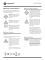
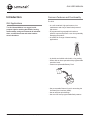
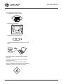
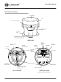
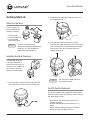
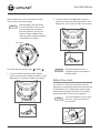
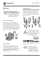
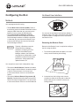
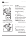
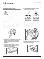
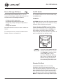
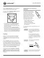

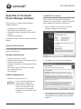
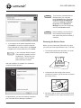
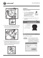
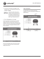
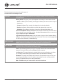
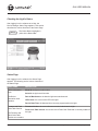
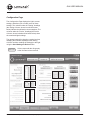
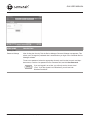
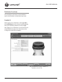
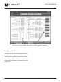
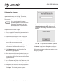
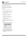
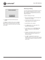
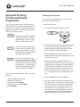
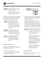
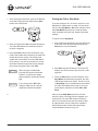
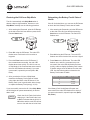
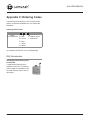
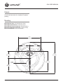
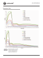
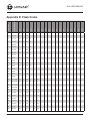
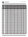
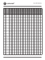
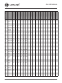
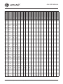
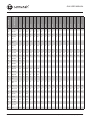
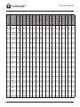
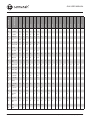

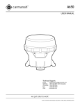
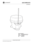
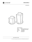


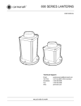


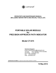


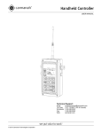
![Installation Manual [PDF 4.6 MB]](http://vs1.manualzilla.com/store/data/006008736_1-137b4e33f3bd3f098e11b56c54272240-150x150.png)