1
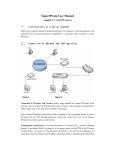
1
AUTODEN – USER MANUAL
2
Table of Contents
1.
Setup Mode ................................................................................................... 3
1.1
1.2
1.3
1.4
1.5
1.6
1.7
1.8
1.9
Introduction ............................................................................................................................................ 3
Entering setup mode ........................................................................................................................... 3
Setup mode PIN ..................................................................................................................................... 5
Run mode PIN ......................................................................................................................................... 6
Font calibration...................................................................................................................................... 7
Assets Management ............................................................................................................................. 8
Pictures Management ....................................................................................................................... 10
Controls Management ...................................................................................................................... 12
Boards Management ......................................................................................................................... 21
2.
Run Mode .................................................................................................... 24
2.1
2.2
2.3
Introduction ......................................................................................................................................... 24
Entering Run Mode............................................................................................................................ 24
Controls in Run Mode ....................................................................................................................... 26
3
1. Setup Mode
1.1 Introduction
The setup mode enables you to define, the names of your assets (flat, house or
even a room) that you intend to automate. For each of those assets, you can
assign one or more pictures where each picture can correspond to a physical
subdivision of your asset (e.g. the saloon of an apartment) or a limited area of a
physical subdivision (e.g. the window side of a living room). The possibilities are
endless, and you can freely use your imagination in that respect according to
your taste and preferences.
1.2 Entering setup mode
When running the application you enter by default the run mode / assets
selection screen, from where you can select the relevant asset name. In the below
example, there is already a created asset called Bakhos Electric:
To enter the setup mode, press the SET button on the top right corner
4
Once you are in setup mode, the below screen will appear:
The following options are possible:
-
SETUP MODE PIN: you can set a 4 digits PIN code to prevent access to the
setup mode
-
RUN MODE PIN: you can set a 4 digits PIN code to prevent access to the
run mode (e.g. preventing children accessing the application and
activating a control that triggers unexpected consequences)
-
GOTO RUNMODE: to return to RUN mode
-
FONT CALIBRATION: to calibrate the default font size, in case the fonts
do not render properly when capturing data in text fields
-
Assets Management: to add or edit assets names
-
Pictures Management: to add or edit a picture for a given asset name
-
Controls Management: to add or edit a control for a given picture
belonging to a given asset name
-
Boards Management: to add a board data for a given asset name
The next sections of this manual will detail each of the above listed options
5
1.3 Setup mode PIN
This screen enables to set a 4 digits passcode preventing access to the setup
mode, and hence minimizing the possibility of foreign tempering with your user
set data:
You can set the four digits passcode by pressing the keypads. There is no
backspace key: you have to clear all digits in case you made a typing error by
pressing CLEAR. Once you have decided about your passcode press the SAVE
button.
Notes:
-
You can not save a passcode with less then 4 digits
Any digits beyond 4 will be ignored
Pressing CLEAR will clear all 4 digits
To cancel the Passcode just clear all 4 digits and press SAVE
To exit the screen press SAVE
6
1.4 Run mode PIN
This screen enables to set a 4 digits passcode preventing access to the run mode,
and hence minimizing the possibility of other persons interacting with your
assets’ automation
You can set the four digits passcode by pressing the keypads. There is no
backspace key: you have to clear all digits in case you made a typing error by
pressing CLEAR. Once you have decided about your passcode press the SAVE
button.
Notes:
-
You can not save a passcode with less then 4 digits
Any digits beyond 4 will be ignored
Pressing CLEAR will clear all 4 digits
To cancel the Passcode just clear all 4 digits and press SAVE
To exit the screen press SAVE
7
1.5 Font calibration
Depending on the device, the default font size in the capture fields, might not
display correctly; in such event, you can recalibrate the font size and vertical
alignment. Note that this setting will only apply to the data capture fields (e.g.
when capturing an asset name)
For example, in the below screen, the reference text in the white background
colored field, is not aligned with its label:
By pressing the buttons FONT DSZ or FONT ISZ, you can change the font size,
and, by pressing the HORIZ DOWN and HORIZ UP buttons you can move the
text up and down:
Using a font size of 12 and a value of 43 for the text height positioning
adjustment gives a satisfactory result. If you are happy with the settings press
SAVE to apply your changes across all capture fields, otherwise CANCEL.
8
1.6 Assets Management
This screen will show the existing assets names that have already been defined
and will enable you to edit them. Besides you can add also new assets name. In
the below screenshot, there is already one asset name defined as Bakhos Electric,
and you can add a new one by pressing the + squared button
Pressing the Back button, will take you one step back in the screens navigation,
which will be in that case, the setup main screen. To edit the existing name
Bakhos Electric, just click the associated button:
9
You have the option to change the name and save the changes by pressing the
SAVE button. If you want to discard the change, just press CANCEL.
Pressing DELETE will delete the asset name, but this will cascade also to any
picture and associated controls and boards to this asset! Unless you are sure
about what you are doing, never delete an asset name! It is not possible to
recover deleted data!
In case you added wanted to add a new asset name, by pressing the before
mentioned + button, you will be prompted with the following screen:
You have the option to define a new asset name and save it by pressing SAVE. To
discard the addition of a new asset name, just press CANCEL, and you will return
to the previous screen
Note that there are no limitations in regard to the number of assets names you
can add; assuming the number of assets names you have defined is N, the
application will compute, depending on the aspect ratio of your device two
integers n and m where n x m > N, in order to represent n rows and m columns
of square buttons associated to the assets names on the screen.
10
1.7 Pictures Management
From here, you can add or edit pictures for a given asset name. You have to
select first the asset name:
In the above screen there is already one asset name defined as Bakhos Electric;
press on the relevant button, and, the following screen will display all the
pictures associated to this asset:
It can be seen that there are four pictures associated to Bakhos Electric and
respectively labeled as Zone 1, Zone 2, Zone 3 and Zone 4.
11
To add a picture, press the + button; this will lead you to the below screen:
Press Select to select a photo from your media browser (Depending on your
device, the media browser will open only in portrait mode), enter a picture name
and press SAVE to save a new picture for the corresponding asset. To discard the
add picture process, press CANCEL and you will return to the previous screen
To edit a picture, press on its on its corresponding thumbnail (back to the
previous page). For instance, if you want to edit the picture for Zone 1, click the
thumbnail bearing the Zone 1 label. This will lead to a similar screen as shown
below:
You can change the picture, by clicking Select to grab a new picture and edit the
picture name within the Picture name field. Press SAVE to record your changes
otherwise CANCEL. Pressing DELETE will delete the picture, but this will
cascade also to any associated controls to this asset! Unless you are sure about
what you are doing, never delete a picture name! It is not possible to recover
deleted data!
12
1.8 Controls Management
The controls managements menu enables you to add or edit controls for a given
asset name, and a given picture name. A brief note about the hardware board
types that are supported:
- Relay board: this board has eight embedded relays each with one NO/16
Amperes contact. Additionally it can interface with an external power
module to read parameters like voltage, current, frequency, power and
consumed power for a single or three-phase system. These additional
parameters can of course be displayed on smartphones/tablets connected
to the same router as the relay board. These relays can activate light
appliances, electric shutters/curtains/doors, heaters, boilers etc…
- Digital input board: this board has eight digital inputs, each 0 or +12Vdc,
that can be displayed on remote smartphones/tablets connected to the
same router as the digital input board. These inputs can for example
display which power source is present (generator or sector power), if a
breaker or thermostat has switched etc... but also can be connected to
user-activated switches around the asset. When a switch is actived, the
digital board can be programmed to issue a command to another board
on the same network (e.g. a relay board ) to toggle light in a corridor for
example...
- Dimmer board: this board has two independent channels, each with a 010Vdc output to control two external dimmers. These dimmers can be for
incandescent/halogen lamp type or Led lamp type. Dimmer control
objects in the application allow users to control the dimmer to the
required lighting level
- Temperature board: this board has two independent channels, each
channel can read a specific temperature from an external sensor and have
it displayed on the user app. The temperature range spans from negative
25deg.C up to 100deg.C. Examples of temperature use can be
outside/inside room temperature or hot water temperature etc…
- Liquid level board: this board is connected to an external pressure sensor
via two wires. Tank dimension are setup up within the board and hence
the pressure level can be converted to liters and remotely read by a
smartphone/tablet etc…
- Scheduler board: this board is not connected to any specific
sensor/interface. It is user-programmable in Run mode to trigger events
such as relays/dimmers in other boards on the same network. The board
has an embedded real-time clock and memory to store up to sixty two
triggers. Example of triggers could be to turn on light in a room or a
shutter at a specific time to wake up the user in the morning, or to turn on
and off the asset boiler to heat the ambient temperature or water at
specific times. It should be noted that the scheduler is weekly-based, that
is each trigger can be programmed several times within the same week,
for example on Monday, Wednesday and Friday only.
The above boards should be installed in a proper electrical enclosure and wired
by a qualified electrician with a prior knowledge of the AutoDen automation
13
system. Country/Location specific laws and regulations regarding the electrical
installation should be observed.
Each of the above boards require an ethernet cable connection with the asset WiFi router. Should the distance or specificities of the asset not allow a direct cable
installation between board(s) and router, then a Wi-Fi repeater can remedy. The
use of Ethernet switches between the board(s) and the Wi-Fi router is of course
feasible since the boards fully comply with the Ethernet standards.
You have to select first the asset name:
In the above screen there is already one asset name defined as Bakhos Electric;
press on the relevant button, and, the following screen will display all the
pictures associated to this asset:
14
Same shown earlier, there are four pictures associated to Bakhos Electric and
respectively labeled as Zone 1, Zone 2, Zone 3 and Zone 4. In this example, Zone 2
will be selected (Click on the relevant thumbnail)
15
This will lead to a screen displaying all the controls associated to the asset name
Bakhos Electric and its picture Zone 2 as seen below:
For instance, it can be seen that there are the following controls:
-
7 buttons
2 User selectable timers
The top left corner button EXT ADR ACCESS sets a default value flag to indicate
whether the application uses local IP addressing or external access (Fixed IP or
DDNS) for the connection when accessing the corresponding picture in run
mode.
At that stage, you can add a control on the screen or edit existing ones. To edit a
control, just tap on it: for instance to edit the control labeled Relay 8 / ON1S,
just tap on it and this will lead you to the following screen:
16
Press SAVE to record your changes (You can also change the control type) or
CANCEL to return to the previous screen. Pressing DELETE will delete the
control and this action cannot be undone!
To add a control on the screen, tap where you would like to have its top left
corner anchored. The following screen will appear:
Same as for editing a control, press SAVE to record your changes (You can also
change the control type) or CANCEL to return to the previous screen. You can
use X, Y, W and H parameters to properly align your controls.
As you noticed, each control has the following properties:
-
X: x coordinate starting from the top left corner of the screen
Y: y coordinate starting from the top left corner of the screen
W: width of the control rectangular area
H: height of the control rectangular area
Type: type of the control (see below)
Board: board number to which the control refer to
Slot: slot number to which the control refer to (on the relevant board)
Font: font size for displaying on screen text
Alpha: alpha transparency factor for the background rectangular area
Display: text color for displaying on screen text
Panel: background color for the background rectangular area
17
Important Notes:
-
Irrespective of the device, the height range is always normalized to 320
virtual pixels, the width (Screen Width) will be considered to be 320
multiplied by the aspect ratio of your device rounded to the lowest
integer. In the case of 16:9 aspect ratio devices, this value will be 568.
Hence, any value you enter for X, Y, W, H must be inline with your screen
settings. For convenience the range of acceptable values for X, Y, W and H
is indicated below their respective labels when editing or creating a
control
-
The minimal value for H is 20
-
The minimal value for W is 20 multiplied by the aspect ratio of your
device and rounded to the lowest integer (It is indicated in the associated
label for the width)
-
The range of values for X, Y, W, H must always satisfy the following
constraints:
o
o
o
o
X + W ⩽ Screen Width (568 in the case of 16:9 aspect ratio devices)
Y + H ⩽ 320
1 ⩽ X ⩽ Screen Width (568 in the case of 16:9 aspect ratio devices)
1 ⩽ Y ⩽ 320
-
The board number must be comprised between 1 and 99. In case you
enter a board number and there is no board defined for this number, you
will not be able to save your data!
-
The slot number must be comprised between 1 and 16. Although, there is
no mean of enforcing that a created or edited control matches exactly the
defined slot number, it is your responsibility to ensure consistency
between an on-screen control and its correspondence with the relevant
board number and slot number
18
-
The possible control types are:
o
o
o
o
o
o
o
o
o
o
o
o
o
o
o
o
o
Button ON: to set a relay to a permanent ON state
Button OFF: to set a relay to a permanent OFF state
Button TOGGLE: to toggle the state of a relay
Button ON1S: to set a relay to an ON state for 1 second only
Button MULTI: multitask button that can run several tasks
Dimmer: to interact with a dimmer channel
UTS: to set a relay ON during a period of time you specify
V1 Read: to read phase 1 voltage
V2 Read: to read phase 2 voltage
V3 Read: to read phase 3 voltage
I1 Read: to read phase 1 current
I2 Read: to read phase 2 current
I3 Read: to read phase 3 current
KW Read: to read the power expressed in Watts
KH Read: to read the cumulative consumed energy in kWh
Hz Read: to read the current frequency
Input Read: digital input read from the relevant DI board
-
The reading of voltage, current and power related figures is only possible
provided the addressed board supports the power meter read function
and is effectively connected to the relevant power meter via the RS485
interface
-
In case of Multitask Button, when you create the control for the first time
you cannot enter the tasks directly. You need to edit it afterwards in
order to define its sequence of tasks to be executed. Also, for Multitask
buttons, you do not need to specify board and slot numbers:
o Creating a sample multitask control:
19
o Multitask button on screen in the bottom right (tap to edit it):
o Editing the control (press the Task Editor button):
o Tasks editor (You can add a new task or return to the controls
display):
20
o Adding a task (e.g. to set a dimmer value):
o Back to the tasks listing after saving:
-
Another important point of note in case of Multitask Button: if you edit it
and change its type (e.g. to BUTTON ON) and save this change, then all
tasks you might have entered previously will be lost! The tasks can only
relate to RELAY ON, RELAY OFF, RELAY ON1S, RELAY OFF, UTS TIMER
and DIMMER. The task editor cannot check the consistency of the board
number and slot number in terms of addressing toward the type of
desired task! It is your responsibility to ensure that you address the
correct board and slot numbers!
21
1.9 Boards Management
Boards Management enables you to add or edit boards for a given asset name.
You have to select first the asset name:
In the above screen there is already one asset name defined as Bakhos Electric;
press on the relevant button, and, the following screen will display all the boards
associated to this asset:
Each thumbnail button is associated to a board and bears its sequence number.
22
To add a picture, press the + button; this will lead you to the below screen:
Enter a board name (description of the board), the external address (fixed IP or
DDNS), local IP address, passkey (8 characters) and the port number. Press
SAVE to save the new board data for the corresponding asset, or press CANCEL
to discard any entry and return to the previous screen.
Note that the following business rules will be enforced:
-
The passkey must be exactly 8 alphanumerical characters
The port number must be greater than 1000 and smaller than 65355
The local IP address must obey the 255.255.255.255 format
The application won’t save the data if one of those rules is violated. For the
external address, it is your responsibility to provide the correct data in the form
of a fixed IP address (such as 194.154.40.190) or a DDNS (myddns.home.com).
Another good practice if you have more than one asset, for example a house and
an office both being automated, would be to pick the local addresses of the
boards in the house to be different than the IPs in the office. In this way you
ensure that if you are in your office and by mistake you press on the house asset
you wouldn’t be communicating with the wrong boards.
23
To edit a board data, press on its on its corresponding thumbnail (back to the
previous page). For instance, if you want to edit the board #2, click the
thumbnail bearing #2. This will lead to a similar screen as shown below:
You can edit the board data from there. Remember though, to respect the
business rules pertinent to the local IP address, passkey and port. Press SAVE to
record your changes otherwise CANCEL. Pressing DELETE will delete the board
data and alter the overall board sequence numbering! Unless you are sure
about what you are doing, never delete a board data! It is not possible to recover
deleted data!
Important Note: assume you have the following configuration:
-
Board 1: Dimmer board
Board 2: Relays board
Board 3: Digital inputs board
Button ON1S associated to Board 2, channel 1
If by mistake you delete Board #2, the board sequencing will become as follows:
-
Board 1: Dimmer board
Board 2: Digital inputs board
Hence, when you will press the ON1S button that was associated to Board 2,
channel 1, the actual command will go the digital inputs board (now #2 in the
sequence), which is totally irrelevant! Therefore great care must be applied
when handling and managing the boards’ definition data!
24
2. Run Mode
2.1 Introduction
The run mode is the default mode for the application: when you start the
application for the first time, you are in run mode. Run mode screens do not have
the top left red banner index that indicates the hierarchy of setup screens. The
main screen of the run mode, is the asset names selection screen as shown
below:
As explained in the previous pages, pressing the SET button will take you to the
setup screens.
2.2 Entering Run Mode
If you are starting the application for the first time, or restarting the application
after having killed its associated process from your device task manager, you
should get to the screen exposed in the previous section. Note that if you have set
(in setup mode) a PIN for the run mode, you will be first prompted to enter this 4
digits PIN code to access the run mode.
25
From the setup mode, navigate to the main setup screen (below) and press the
GOTO RUN MODE button on the bottom of the screen:
Once you are in the run mode main screen (shown in section 2.1), click on the
relevant thumbnail to select your asset name (For instance Bakhos Electric). This
will take you to the following screen:
Select the relevant picture to run automation commands or read data feedback
from data gathering boards. In this example, Zone 2 will be selected
26
This will open the below screen:
2.3 Controls in Run Mode
Control
Category
Dimmer
Generic
Graphical Pattern
Min
-
0
User set Title
+
Associated Actions
Comments
Max
-
Min: sets dimmer value to 0
Max: sets dimmer value to
25
(-): Decrements dimmer
(+): Increments dimmer
For ON, ON1S, OFF and TOGGLE
buttons:
Button
(ON, OFF,
ON1S,
TOGGLE,
MULTITASK)
-
User set Title
Taping the button triggers
the relevant action
Depending on the board
feedback, the background
color will be green if the
associated relay is ON
otherwise red. Note that if
no feedback is received
from the background color
will be orange
For multitasks buttons, taping the
button will trigger the chain of tasks
programmed for this button
27
The UTS timer is a control
associated to a relay on a given
board. It is possible to select a time
value of HH:MM:SS by using the
relevant (+) and (-) sub-buttons
from left to right
Start
UTS
Timer
Stop
+
+
+
00
00
00
-
-
-
User set Title
Pressing the Start sub-button
triggers the UTS timer in
countdown mode starting from
HH:MM:SS while setting the
corresponding relay to an ON state.
When the timer countdown reaches
00:00:00 the corresponding relay
returns to an OFF state
Pressing Stop at any time cancels
the countdown and sets the
corresponding relay to an OFF state
Analog
Value
Read
Digital
Value
Read
Value
User set Title
User set Title
Reads a value from a board
connected to a power meter. It is
possible to read voltage, current,
power
in
Watts,
power
consumption in kWh and frequency
in Hz
The background of this control is
green if the corresponding input
from the board is TRUE, otherwise
the background will be red
For any questions, comments or clarifications regarding the above information
or the AutoDen system in general, please do not hesitate to email us at:
[email protected]
[email protected]
Other information about the AutoDen automation system and also other
products by Elebak company can be found on our website: www.elebak.com
28
END