1
BRUCIATORI
CALDAIE MURALI E TERRA A GAS
GRUPPI TERMICI IN GHISA E IN ACCIAIO
GENERATORI DI ARIA CALDA
TRATTAMENTO ACQUA
CONDIZIONAMENTO
AZIENDA CERTIFICATA ISO 9001
-VI
0444 351044
"
RE 'USO
A
N D
EG ALE
S
N U
E
CO AN
I
TH
M
S "
T
A
A
E
H D
EG TO T
PR SER TEN
E T NDE
R
U
U A
N
L'I SIG.
E S IS H
K
L
A L"
E
A
E MNUA USER AD D L
S
A A
E
ILIDRIO
PLE E M THE
B
A
S
A
O
"U ER T
AM USU
A
V
L
L
A "
O
AN RLE USO
G
A
O
TENREG L DE
T
A
AR
U
N
G
E AN
RE O"
NT E US
"M
E
R
D
VO AL TE
FA ANU TEN
U
"M SR.
AO
Le illustrazioni e i dati riportati sono indicativi e non impegnano. La LAMBORGHINI si riserva il diritto di apportare senza
obbligo di preavviso tutte le modifiche che ritiene più opportuno per l'evoluzione del prodotto.
The illustrations and data given are indicative and are not binding on the manufacturer. LAMBORGHINI reserves the right to
make those changes, considered necessary, for the improvement of the product without forwaming the customer.
Las ilustraciones y los datos son indicativos y no comprometen. LAMBORGHINI se reserva el derecho de realizar sin preaviso
todas las modificaciones que estime oportuno para la evolución del producto.
As ilustrações e os dados existentes são indicativos e não compromissivos. A LAMBORGHINI reserva-se o direito de efectuar,
sem a obrigação de pré-aviso, todas as modificações que considerar necessárias para a melhoria do produto.
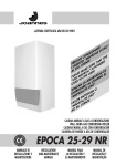
CALDAIA MURALE A GAS PER ESTERNO - ALTO RENDIMENTO - MODULANTE
WALL-HUNG GAS BOILER FOR OUTDOOR INSTALLATION - HIGH EFFICIENCY - MODULATING UNIT
CALDERA MURAL A GAS PARA EXTERIOR - ALTO RENDIMIENTO - MODULANTE
CALDEIRA DE PAREDE A GÁS PARA AMBIENTES EXTERNOS - ALTO RENDIMENTO - MODULÁVEL
LAMBORGHINI CALOR S.p.A.
VIA STATALE, 342
44040 DOSSO (FERRARA)
ITALIA
TEL. ITALIA 0532/359811 - EXPORT 0532/359913
FAX ITALIA 0532/359952 - EXPORT 0532/359947
Cod. 97.50419.0 11/00
24 MCS W TOP U/IT
MANUALE DI
INSTALLAZIONE E
MANUTENZIONE
INSTALLATION
AND MAINTENANCE
MANUAL
MANUAL PARA
LA INSTALACIÓN Y
EL MANTENIMIENTO
MANUAL DE
INSTALAÇÃO E
MANUTENÇÃO
100
37
INDEX
PAGE
GENERAL INSTRUCTIONS _______________________________________________ 39
DESCRIPTION _________________________________________________________ 40
MAIN COMPONENTS __________________________________________________ 41
DIMENSIONS _________________________________________________________ 42
TECHNICAL FEATURES __________________________________________________ 42
NOZZLE CALIBRATION__________________________________________________ 43
ELECTRICAL CONNECTIONS - WIRING DIAGRAMS _________________________ 44
INSTALLATION AND START-UP ___________________________________________ 47
SETTING THE TIME/DAY OF THE WEEK ___________________________________ 48
MODES ______________________________________________________________ 48
“AUTOMATIC” TEMPERATURE CONTROL MODE ____________________________ 49
“MANUAL” TEMPERATURE CONTROL MODE _______________________________ 50
SETTING THE TEMPERATURE _____________________________________________ 51
VIEWING MAIN BOILER PARAMETERS ____________________________________ 52
RE-ESTABLISHING FACTORY SETTINGS AND CONTROL RESET ________________ 53
ERROR MESSAGES _____________________________________________________ 53
INSTALLER SETTINGS ___________________________________________________ 54
HYDRAULIC CONNECTION _____________________________________________ 56
HYDRAULIC CIRCUIT ____________________________________________________ 57
INSTALLATION _________________________________________________________ 58
STARTING UP __________________________________________________________ 58
FLUE EXHAUST TYPES ___________________________________________________ 59
FLUE EXHAUST CONNECTION ___________________________________________ 60
FLUE EXHAUST INSTALLATION ___________________________________________ 62
ADJUSTMENTS ________________________________________________________ 63
SWITCHING OFF ______________________________________________________ 64
MAINTENANCE _______________________________________________________ 64
OPERATION WITH DIFFERENT TYPES OF GAS ______________________________ 65
ANTI-FREEZE KIT (ON REQUEST) _________________________________________ 66
FAULT-FINDING CHART _________________________________________________ 67
Congratulations....
......on an excellent choice.
We thank you for the preference accorded to our products.
LAMBORGHINI CALORECLIMA has been actively present in Italy and throughout the world since
1959 with a widespread network of agents and concessionary agents to constantly guarantee the
presence of our product on the market. Alongside this is the support of a technical service,
“LAMBORGHINI SERVICE”, which is entrusted with the qualified servicing of the product.
For the installation and positioning of the boiler:
CAREFULLY OBSERVE THE LOCAL REGULATIONS IN FORCE
38
99
ÍNDICE
PÁGINA
NORMAS GERAIS ____________________________________________________ 101
DESCRIÇÃO _________________________________________________________ 102
COMPONENTES PRINCIPAIS ___________________________________________ 103
DIMENSÕES ________________________________________________________ 104
CARACTERÍSTICAS TÉCNICAS _________________________________________ 104
REGULAÇÃO DO GÁS-BICOS _________________________________________ 105
LIGAÇÕES ELÉCTRICAS - ESQUEMAS ___________________________________ 106
INSTALAÇÃO E UTILIZAÇÃO __________________________________________ 109
PROGRAMAÇÃO DO HORÁRIO E DO DIA DA SEMANA __________________ 110
SELECÇÃO DAS FUNÇÕES ____________________________________________ 110
PROGRAMAÇÃO PARA O FUNCIONAMENTO EM AUTOMÁTICO DO CONTROLO CLIMÁTICO __ 111
FUNCIONAMENTO EM MANUAL DO CONTROLO CLIMÁTICO _____________ 112
PROGRAMAÇÃO DA TEMPERATURA ___________________________________ 112
VISUALIZAÇÃO DOS PARÂMETROS DO ESTADO DA CALDEIRA ____________ 114
REPOSIÇÃO DOS DADOS DA FÁBRICA E “RESET” DO CONTROLO _________ 114
SINALIZAÇÃO DE MENSAGENS ERRADAS ______________________________ 115
PROGRAMAÇÃO DO INSTALADOR ____________________________________ 115
LIGAÇÃO HIDRÁULICA _______________________________________________ 118
CIRCUITO HIDRÁULICO _______________________________________________ 119
INSTALAÇÃO _______________________________________________________ 120
LIGACAO ___________________________________________________________ 120
TIPOS DE DESCARGA ________________________________________________ 121
LIGAÇÃO DA DESCARGA DOS FUMOS _________________________________ 122
INSTALAÇÃO DA DESCARGA DOS FUMOS _____________________________ 124
REGULAÇÕES _______________________________________________________ 125
DESLIGAMENTO _____________________________________________________ 126
MANUTENÇÃO _____________________________________________________ 126
FUNCIONAMENTO COM DIVERSOS TIPOS DE GÁS ______________________ 127
KIT ANTIGELO (A PEDIDO) ____________________________________________ 128
IRREGULARIDADES DE FUNCIONAMENTO ______________________________ 129
Parabéns...
... pela óptima escolha.
Agradecemos a preferência dada aos nossos produtos.
A LAMBORGHINI CALORECLIMA encontra-se em actividade desde 1959 em Itália e no mundo com
uma vasta rede de Agentes e Concessionários, que garantem a presença constante dos seus produtos
no mercado. Junta-se a esta rede um serviço de assistência técnica, “LAMBORGHINI SERVICE”, que
garante uma manutenção qualificada do produto.
Para a instalação e colocação da caldeira:
RESPEITAR ESCRUPULOSAMENTE AS NORMAS LOCAIS EM VIGOR.
98
IRREGULARIDADES EN EL FUNCIONAMIENTO
DEFECTO
1 NO SE
ENCIENDE
GENERAL INSTRUCTIONS
CAUSA
SOLUCIÓN
A.Grifo del gas cerrado
B. Pulsador en bloqueo
C. Falta detección de llama
D. Falta descarga eléctrica de encendido
E. Presencia de aire en la tubería
F. Ha intervenido el termostato de
seguridad
G. No hay circulación de agua
H.La temperatura del agua de la caldera
es superior a la posición del termostato de regulación
A. Abran la llave del gas
B. Rearmar presionándolo
C. Inversión fase neutro
D. Llamen al técnico
E. Repitan el arranque
F. Presionar el pulsador de rearme
G. Restablezcan la presión en la caldera
y controlen el circulador
H. Coloquen el termostato de regulación
a la temperatura deseada
2 NO SE ENCIENDE A. Llama defectuosa
B. Caudal del gas insuficiente o mal
SUAVEMENTE
regulado
A. Llamen al técnico
B. Llamen al técnico
A. Controlen las tuberías externas.
Controlen las tuberías internas.
Llamen al técnico
A.Conducto de humos de sección, altura o A. Reemplacen las partes no adecuadas
4 OLOR DE
B. Regulen el caudal del gas.
empalme no adecuados a la caldera
GASES NO
QUEMADOS Y B. Consumo de gas excesivo - el estado C. Controlar y maniobrar en el estabilizador
de presión de la válvula del gas
de combustión es imperfecto
MALA
D. Controlen que estén bien limpios los
C. Las llamitas tienden a separarse
COMBUSTIÓN
D. La llama presenta puntas amarillas
puntos de paso del aire y de los conos
DEL
venturi del quemador.
QUEMADOR
Una vez comprobados los puntos A-B-C-D,
si dan resultado negativo llamen al técnico.
A. Chimenea de sección o altura no
A. Reemplacen las partes no decuadas.
5 LA CALDERA
adecuada (dimensiones excesivas)
B. Regulen el termostato de la caldera a una
PRODUCE
temperatura superior y comprueben que
CONDENSACIÓN B. La caldera funciona a una temperatura
funcione correctamente el tubo de
demasiado baja
aspiración/expulsión humos.
3 OLOR DE GAS
A. Pérdida en el circuito de las tuberías
(externas e internas a la caldera)
6 LOS
RADIADORES
ESTÁN FRÍOS
EN INVIERNO
A. El interruptor verano-invierno, está en
posición verano
B. El termostato ambiente está regulado
demasiado bajo o es defectuoso
C. Instalación o radiadores cerrados
D. El circulador está bloqueado
E. La válvula de 3 vías no funciona
7 PRODUCE
POCA AGUA
CALIENTE
SANITARIA
A. La temperatura del termostato de
precedencia es baja
B. La válvula de 3 vías no funciona
39
A. Cámbienlo a la posición de invierno
B. Regulen el termostato a una temperatura más alta o cámbienlo
C. Comprueben que las válvulas de corte
de la instalación y los grifos de los
radiadores estén abiertos. Si el punto
C da un resultado negativo llamen al
técnico
D. Con un destornillador desbloqueen, y
controlen la alimentación eléctrica
E. Verificar la alimentación eléctrica
A. Regulen el termostato de precedencia
a temperatura superior o sustituirlo.
B. Verificar la correcta alimentación
eléctrica y la correcta colocación del
cuerpo válvula.
● This booklet constitutes an integral and essential part of the product.
Read carefully the instructions contained in this booklet as they provide important directions regarding the
safety of installation, use and maintenance. Preserve this booklet with care for any further consultation.
The installation of the boiler must be carried out in compliance with current regulations, according to the
instructions of the manufacturer and by qualified personnel. An incorrect installation can cause injury or
damage to persons, animals and objects, for which the manufacturer cannot be held responsible.
● After removing the packaging materials, check the content integrity. In case of doubt, do not use the unit
and contact the supplier. The packaging material (wooden crates, nails, clips, plastic bags, foam, etc.)
must not be left within reach of children as they are potential sources of danger.
● This boiler is designed to heat water to a temperature below boiling (atmospheric pressure). It must be
connected to a heating system compatible with its performances and output.
● This appliance should be destined only for the use for which it has been expressly envisaged. Any other
use is to be considered improper and therefore dangerous. The manufacturer cannot be considered
responsible for any damages caused from improper, erroneous or unreasonable use.
ALL INSTALLATION, MAINTENANCE AND GAS CONVERSION OPERATIONS MUST BE CARRIED OUT BY
AUTHORISED SKILLED TECHNICIANS.
TO ENSURE THAT BOILER IS INSTALLED CORRECTLY AND THAT IT FUNCTIONS PROPERLY, WE RECOMMEND
THAT ONLY LAMBORGHINI ACCESSORIES AND SPARE PARTS BE USED.
ON NOTICING THE SMELL OF GAS DO NOT TOUCH ANY ELECTRIC SWITCH. OPEN DOORS AND WINDOWS,
SHUT OFF THE GAS COCKS.
WARNING: FIT A SAFETY DEVICE ON THE FLUE EXHAUST DUCT SO AS TO ELIMINATE ANY SOURCE OF
DANGER TO CHILDREN OR ADULTS AND PREVENT CONTACT WITH FLAMMABLE MATERIALS.
40
97
DESCRIPTION
KIT ANTICONGELANTE (A PETICIÓN)
The THIN boiler has been designed for outdoor installation in partially protected areas and can operate at
winter temperatures as low as –15°C. It is largely intended for installation on balconies and terraces. This unit
is practically “invisible” as it is designed to be wall-mounted just 80 mm above the floor.
The boiler is equipped with an anti-freeze system designed to protect the heating and domestic hot water
circuits; when necessary, this ignites the burner until the set minimum water temperature is restored. To cover
all eventualities, an electrical element kit, to be fitted on the domestic hot water circuit, is also available.
This unit has passed all the tests required by strict European Community safety standards.
The boiler has IP44 protection rating, is fully automatic with continuous flame modulation and ionisation
ignition; it is C-type and can be installed as a sealed chamber or fan-forced draught unit.
All ignition, shut-down, adjustment, programming, display and self-diagnosis functions are effected by a
master remote control unit.
La caldera THIN tiene de serie un dispositivo anticongelante que protege el circuito hidráulico. Tal dispositivo entra en
funcionamiento cuando la temperatura se acerca al valor de 6°C. Como ulterior protección del circuito sanitario, se puede
instalar en el sitio, un KIT ANTICONGELANTE que entra en funcionamiento a una temperatura de 4°C.
Detalle A
Detalle B
Composición KIT ANTICONGELANTE
1 Resistencia adhesiva 72 x 42 - 230V - 12W
2 Resistencia adhesiva 200 x 53 - 230V - 30W
3 Termostato anticongelante 4°C - 14°C
4 Capuchón aislante de silicona
5 Vaina aislante Ø 16 interno x 70 mm.
6 Aislador pasapanel
7 Tornillos autorroscantes
INSTALACIÓN RESISTENCIAS
8 Aro barril
Aplicar las resistencias 1 y 2 respetando el sentido indicado en
9 Tric cables resistencia
la figura. Fijar el termostato 3 utilizando los tornillos 7 en la
10 Cambiador rápido
base presente en el tubo de entrada sanitario y conectar los
11 Cuadro eléctrico
faston presentes. Introducir los cables eléctricos en el cuadro
12 Entrada agua fría
eléctrico teniendo el cuidado de colocar correctamente el aislador
13 Salida agua caliente
pasapanel 6 en dotación. Conectarlos a los bornes FA1 y FA2
14 Entrada sanitario
como ilustra la figura (detalle B)
96
FUNCIONAMIENTO CON DISTINTOS TIPOS DE GAS
41
MAIN COMPONENTS
TRANSFORMACIÓN DE GAS NATURAL A GAS LÍQUIDO
Procedan a la sustitución de los inyectores del quemador, introduzcan el diafragma (I) presente en el kit correspondiente,
sustituir además el muelle (C) situado debajo de la varilla de la bobina (E), respetando el sentido del montaje. Desplazar
el puente en la tarjeta modulación, desde la posición GAS NATURAL a la posición B-P. A continuación procedan a la
verdadera regulación como indica el apartado “REGULACIONES”, pág. 94. Para el diámetro de los inyectores y la
presión del gas de funcionamiento vean la tabla ilustrada a continuación.
Tipo de gas
GAS NATURAL
(G20-20mbar)
GAS LÍQUIDO B
(G30-28/30mbar)
GAS LÍQUIDO P
(G31-37mbar)
min.
max.
m3/h
Inyectores
quemador
Ø mm.
2
11
3,06
1,25
8.550
-
5
25
0,89
0,77
29.330
5,4
6,2
32
1,17
0,77
22.360
5,4
Presión en los inyectores mbar
N
DESCRIPCIÓN
A
B
C
D
E
F
G
H
I
L
N
Tornillo reg. potencia max.
Contratuerca bloqueo regulación
Muelle
Tornillo regulación potencia mínima
Bobina
Resorte
Toma de presión
Centralita
Diafragma gas (eventual)
Toma de compensación
Encendido lento (RLA)
Caudal
kcal/h
Diafragma
gas (M)
Ø
P.C.I.
LEGEND
1
2
3
4
5
6
7
8
9
10
11
12
13
14
Ignition electrodes
Manual air purge valve
Fumes fan
Total safety thermostat
Fumes pressure switch
Heating detector
3-way valve
Hydrometer
Filling cock
Reset push-button with lock-out warning light
Hot water pressure switch
Lack of water pressure switch
Manual air purge valve
Electric box
15
16
17
18
19
20
21
22
23
24
25
Instantaneous water-heater
Hot water circuit drain cock
Hot water detector
Automatic air purge valve
Circulating pump
Heating safety valve
Heating circuit drain cock
Gas cock
Gas valve
Electronic control unit
Expansion tank
42
DIMENSIONS mm
95
PARADA
PARADA PROLONGADA CON CALDERA INSTALADA EN EL INTERIOR
Si la caldera tiene que permanecer inactiva por mucho tiempo, hay que cerrar la llave del gas y desconectar
el aparato de la corriente.
PARADA PROLONGADA CON CALDERA INSTALADA EN EL EXTERIOR
Si la caldera tiene que permanecer inactiva por mucho tiempo, hay que cerrar la llave del gas y desconectar
el aparato de la corriente. En el caso de peligro de hielo, vaciar el circuito sanitario y dejar el circuito de la
calefacción lleno con el líquido anticongelante.
Nota:
TECHNICAL FEATURES
Thermal capacity
MODEL
Min. thermal
capacity
Connections
Operating
pressure
Hot water
supply
Hot water system Heating Hot water Continuous Min.
Main system
circuit circuit supply supply
Supply Return Gas Inlet Outlet
min. max. ∆30ºC
kW kcal/h kW kcal/h kW kcal/h kW kcal/h Ø Ø Ø Ø Ø bars bars bars l/min. l/min.
Input
Output
Input
Output
THIN
24MCS W TOP 30,45 26.187 27,7 23.822 14,2 12.212 12,66 10.887 3/4” 3/4” 3/4” 1/2” 1/2”
Boiler version: mod. C type C12-C32-C42-B22
Category: II 2H3+
3
0,4 6 13,2 2,5
con la caldera nueva o después de un período
largo de inactividad puede que se bloquee el
circulador; en este caso es necesario desenroscar
el tapón delantero y girar con un destornillador
el eje del motor colocado debajo.
Expansion
Weight
tank
MANTENIMIENTO
l
kg
8
56
Las siguientes operaciones están estrictamente reservadas a personas cualificadas; les rogamos que se pongan
en contacto por lo tanto con la organización:
Max. water temperature 90°C
Rated gas pressure: Natural gas 20 mbars
B 28/30 mbars - P 37 mbars
CIRCULATING PUMP FEATURES
SERVICE
Delivery/pressure available at the system
CONTROLES ESTACIONALES
Antes de que empiece la estación invernal hay que efectuar un control general del aparato, de la instalación,
de la chimenea, y en particular:
●
●
●
●
●
●
●
●
la presión de la instalación hidráulica;
la eficiencia de la instalación hidráulica;
el funcionamiento de los termostatos de regulación y de seguridad;
el funcionamiento del circulador;
el desarrollo de la combustión (CO-CO2).
la expulsión humos;
el estado del quemador y si fuera necesario limpiarlo;
la hermeticidad del circuito de gas y el buen funcionamiento de la válvula del gas.
94
43
REGULACIONES
GAS - NOZZLE CALIBRATION
La caldera prevé la posibilidad de adoptar la potencia térmica en calefacción a la demanda térmica de los
locales que haya que calentar (sin que varíe la potencia disponible para la producción de agua caliente
sanitaria).
Todas las calderas salen de la fábrica ajustadas al 70% de su potencia máxima. Para adaptar la caldera a la
potencia solicitada por la instalación hay que efectuar las operaciones siguientes:
The boilers leave the factory calibrated and predisposed to operate with NATURAL GAS and LIQUID GAS.
These calibrations are effected without the connection of the compensating joint (Pos. A).
For the calibrations to put into effect, see the table related below:
Gas type
● introducir un manómetro en la toma de presión (G)
● alimentar eléctricamente la válvula gas poniendo el selector en la posición INVIERNO
● intervenir en el potenciómetro de calefacción (1) situado en la tarjeta modulación hasta alcanzar la
presión de gas requerida por la potencialidad de la instalación de calefacción (ver curvas de presión).
NATURAL GAS
Si fuera necesario intervenir en la regulación de la potencialidad mínima y máxima (pre calibradas en
fábrica),para la producción de agua sanitaria, efectúen las siguientes operaciones:
(G30-28/30mbars)
● desunir los contactos de alimentación de la bobina (E)
● alimentar eléctricamente la válvula de gas con la caldera encendida en la posición VERANO y trasegar
agua caliente sanitaria al máximo del caudal (13,1 l./minuto)
● apretar a fondo, sin la ayuda de herramientas, el tornillo de regulación (D)
● aflojar la contratuerca (B)
● maniobrar con una llave en el tornillo (A) de la bobina hasta obtener los valores de presión de gas
máximos citados en la pag. 74
● bloquear la contratuerca (B)
● destornillar el tornillo de regulación (D) hasta alcanzar los valores de presión de gas mínimos citados en la pag. 74
● volver a conectar la bobina (E)
(G20-20mbars)
LIQUID GAS B
LIQUID GAS P
(G31-37mbars)
min.
max.
m /h
Burner
nozzles
Ø mm.
2
11
3,06
1,25
8.550
5
25
0,89
0,77
29.330
6,2
32
1,17
0,77
22.360
Pressure on nozzles mbars
Delivery
3
L.C.V.
kcal/h
BURNER PRESSURE CURVES - OUTPUT
Tales operaciones permitirá ahora a la caldera, satisfacer las exigencias de los utilizadores.
NOTA: Para realizar este ajuste es necesario utilizar un manómetro de columna de agua conectándolo a la
toma de presión (G).
DESCRIPCIÓN
A
B
C
D
Tarjeta modulación
E
F
G
H
I
L
Tornillo reg. potencia max.
Contratuerca bloqueo
regulación
Muelle
Tornillo regulación
potencia mínima
Bobina
Resorte
Toma de presión
Centralita
Diafragma gas
(eventual)
Toma de compensación
A Compensating joint
B Connecting pipe
To effect the gas valve calibration,
proceed as follows:
a) take the pipei B off the joint A;
b) effect calibration;
c) connect the pipe B again to the joint A.
44
93
ELECTRICAL CONNECTIONS - WIRING DIAGRAMS
INSTALACIÓN CONDUCTOS EXPULSIÓN DE HUMOS
The boiler must be connected to an earthed, single-phase 220-230V-50 Hz mains supply by means of a threewire cable, ensuring that connections to the LINE and NEUTRAL terminals are made correctly.
A bipolar switch must be used with contacts opening to at least 3 mm.
The power lead must only be replaced by another with the following characteristics: “HAR H05 VV-F” 3 X 0.75
mm2.
The boiler is equipped with a 1 m lead for connection of the remote control unit. If this is not long enough for
the intended control unit position it must be replaced with a lead of appropriate length.
The control unit must be fitted on an internal wall about 1.5 m above the floor. Do not fit near heat sources or
in direct sunlight. Avoid installation in corners, alcoves, behind doors or curtains etc.
Attach the unit to the wall with the supplied expansion plugs. A through-hole is previewed to allow for passage
of the electrical wiring. The control unit can also be fitted directly on a standard 3-module junction box.
Connection to the boiler requires two wires with a minimum cross-section of 0.5 mm2 which must not exceed
50 m in length. The positive pole is to be connected to terminal 5 and the negative pole to terminal 4.
Accidental inversion of polarity, while not damaging the control unit, will stop it functioning.
CONDUCTO EXPULSIÓN CONCÉNTRICO
Monten la curva concéntrica colocándola en la dirección deseada, introduzcan en la misma la junta estanca. Monten los
tubos de aspiración y de expulsión de los humos respetando las dimensiones indicadas en el correspondiente esquema de
instalación. Hay que mantener el conducto de expulsión de humos ligeramente inclinado hacia el exterior.
Installation must be made in compliance with safety REGULATIONS IN FORCE.
Make a good earth connection.
Voltage
Frequency
V
Hz
230
50
Absorbed
power
Protection
index
Noise level
kW
IP
dB (A)
0,148
44
45
CONDUCTO
EXPULSIÓN HUMOS
RAMIFICADO
CONDUCTO EXPULSIÓN
HUMOS DE TIRO FORZADO
(B22)
ELECCIÓN DEL DIAFRAGMA AIRE (A)
Conducto expulsión tiro forzado (B22)
Ø82 mm.
Conducto expulsión concéntrico de 0,35 m a 1 m Ø82 mm.
Conducto expulsión concéntrico de 1 m a 3 m Ø94 mm. ESTÁNDAR
Conducto expulsión/aspiración ramificado
Ø94 mm. ESTÁNDAR
Longitud max. CONDUCTO EXPULSIÓN TIRO FORZADO (B22) 7,5 m.
Longitud max. CONDUCTO EXPULSIÓN CONCÉNTRICO 3m.
Longitud max. CONDUCTO EXPULSIÓN RAMIFICADO CON DIAFRAGMA
Ø 82 (Aspiración + Ida) 6 m.
Longitud max. CONDUCTO EXPULSIÓN RAMIFICADO CON
DIAFRAGMA Ø 94 (Aspiración + Ida) 18m.
La instalación de una curva en la unión de la caldera a la chimenea crea una pérdida de presión.
Los valores de la tabla indican una reducción de tubería lineal.
INSTALACIÓN TIPO
COLOCACIÓN CURVA A 90°
COLOCACIÓN CURVA A 45°
0,6 mt.
0,3 mt.
Conducto expulsión concéntrico
1 mt.
0,5 mt.
Expulsión/Aspiración separados
0,6 mt.
0,3 mt.
Conducto expulsión tiro forzado (B22)
Atención: Utilicen sólo y exclusivamente el kit de Aspiración/Expulsión humos Lamborghini Caloreclima.
92
EXPULSIÓN/ASPIRACIÓN
1
2
3
4
5
45
PRINCIPLE DIAGRAM
Concéntrico para terraza
Tiro forzado (B22) para conducto
Ramificados, para conductos separados
Concéntricos, conexiones a conductos concéntricos
Tiro forzado (B22) para techo
Consulten las normas vigentes por lo que respecta a la colocación y a las distancias de los terminales de tiro
desde las puertas, ventanas, etc....
LEGEND
BM
CA
CiR
EC
ES
L
MAX R
N
PF
Pma
PR
P.risc.
PS
P.san.
RT
Modulating coil
Ignition control unit Honeywell
Circulating pump
Control electrode
Spark electrode
Line
Max. heating setting
Neutral
Fumes pressure switch
Lack of water pressure switch
Reset push-button
Heating potentiometer
Hot water pressure switch
Hot water potentiometer
RL3 relay contact
RS
RP
RF
SB
SR
SS
SW1
TIMER
TR1
TST
V
VG
VN
R4 relay contact
RL2 relay contact
Anti-interference resistance
Lock-out warning light
Heating detector
Hot water/water-heater detector
Function selector
Boiler timer adjustment
Transformer
Total safety thermostat
3-way valve
Gas valve
Fan
NOTE: Slow ignition (RLA) is of the mechanical type positioned on the gas valve as illustrated in the figure on page 65.
91
46
CONEXIÓN SALIDA HUMOS
CIRCUIT DIAGRAM
UNIÓN A LA CHIMENEA VERSIÓN TIRO FORZADO (B22)
La caldera está preparada para poderse acoplar a una chimenea y/o a un conducto de humos, que debe
tener los siguientes requisitos:
●
●
●
●
●
●
●
●
●
+-
que sea estanco, como lo ha de ser también la unión a la chimenea;
que sea de material idóneo;
que la unión esté a la vista;
utilizar para los cambios de dirección curvas a 90° y a 45°;
que no tenga dispositivos de secionamento;
que tenga el eje del tramo terminal de entrada perpendicular a la cara interna opuesta a la chimenea;
que esté sujeto sólidamente a la boca de manera hermética, sin que sobresalga por dentro;
si fuera posible, que reciba sólamente la expulsión de humos de una caldera;
que respete las normas locales vigentes.
NOTE: Check that the
microswitches on selector
SW1 are as illustrated in the
diagram.
LEGEND
BM
CA
CR
CiR
EC
ES
KA
L
MAX R
N
PF
Pma
PR
P.risc.
PS
P.san.
Modulating coil
Ignition control unit Honeywell
Remote control - room thermostat
Circulating pump
Control electrode
Spark electrode
Anti-freeze thermostat (on request)
Line
Max. heating setting
Neutral
Fumes pressure switch
Lack of water pressure switch
Reset push-button
Heating potentiometer
Hot water pressure switch
Hot water potentiometer
RA
RF
SB
SC
SR
SRT
SS
SW1
TIMER
TR1
TST
V
VG
VN
Anti-freeze element
Anti-interference resistance
Lock-out warning light
Connection card
Heating detector
RX-TX board
Hot water/water-heater detector
Function selector
Boiler timer adjustment
Transformer
Total safety thermostat
3-way valve
Gas valve
Fan
UNIÓN A LA CHIMENEA VERSIÓN CÁMARA ESTANCA (C12-C32-C42)
La caldera realiza la combustión en una cámara estanca con respecto al ambiente por lo que no requiere
ninguna ventilación especial y puede colocarse por lo tanto en cuartos, trasteros, o talleres técnicos. Hay
varias posibilidades para poder expulsar los productos de la combustión y aspirar el aire del exterior; la
caldera prevé fundamentalmente dos tipos base de expulsión/aspiración:
● expulsión/aspiración de tipo concéntrico,
● expulsión/aspiración de tipo ramificado.
De esta manera es posible, mediante los kits previstos, unir la caldera a conductos concéntricos, conductos de
ventilación, chimeneas separadas, etc... En la página 92 hemos esquematizado algunas de las soluciones
posibles.
90
47
TIPOS DE CONDUCTOS EXPULSIÓN HUMOS
INSTALLATION AND START-UP
La caldera deberá ser instalada y funcionar en el exterior.
Aconsejamos para la instalación utilizar exclusivamente accesorios LAMBORGHINI.
Remove the control unit base-block by levering the two lower hooks (fig. 1).
KIT EXPULSIÓN HUMOS VERSIÓN DE TIRO
FORZADO
Para la instalación del kit de tiro forzado, insertar el
tronco 1 en dotación con la caldera, en el ventilador,
interponer el diafragma 3 y la guarnición adhesiva
2. Fijar el tronco rebordeado 4 con los específicos
tornillos e introducir la brida de silicona 5. La brida
deberá apoyar en la parte superior de la caldera para
evitar que entre el agua.
fig. 1
fig. 2
Fix the control unit to the wall via the holes in the base-block. This should be mounted 1.5 m above the floor in
an area well away from entry/exit doors, windows or other factors that might influence room temperature
readings (fig. 2).
After making sure that electrical power at the boiler is OFF proceed with the electrical connections using bipolar wiring: do not route the wiring parallel to the main power supply wires/leads.
If it is not possible to avoid taking the same wiring route use a shielded lead, the braid of which must be
connected to an earth.
Connect the lead extremities to the ”+IN+” terminal block (fig. 3). It is highly important that you observe the
indicated polarities (boiler + to control +, boiler – to control -)
Lead length must not exceed 50 m.
KIT EXPULSIÓN HUMOS ONCÉNTRICO
Para la instalación del Kit concéntrico insertar el tronco 1 en dotación con la caldera, en el ventilador,
interponer el diafragma 3 y la guarnición adhesiva
2 y la de espesor 5 mm. 4. Fijar la curva 5 con los
correspondientes tornillos e insertar la brida de
silicona 6 en dotación. La brida deberá apoyar en
la parte superior de la caldera para evitar que entre
el agua.
BOILER
CONTROL
UNIT SWITCH
OUTDOOR
SENSOR
KIT EXPULSIÓN HUMOS RAMIFICADO
Para la instalación del Kit ramificado insertar el tronco 1 en dotación con la caldera, en el ventilador,
interponer el diafragma 3 y la guarnición adhesiva 2
y la de espesor 5 mm. 4. Fijar el kit expulsión
ramificado 5 con los correspondientes tornillos e
insertar la brida de silicona 6 en dotación. La brida
deberá apoyar en la parte superior de la caldera para
evitar que entre el agua.
Atención
la caldera está predispuesta so
lamente para el kit de expulsión
ramificado alto.
+ BOILER
- BOILER
fig. 3
89
48
Once the connections have been made power up the boiler and, after the “CON” signal, check that the legend
“OFF” appears on the main display and that the time 00:00 on the lower display and the day indicator both
INSTALACIÓN
.
appear
If the legend “CON” persists this indicates improper connection of the control unit to the boiler.
NOTE: In the event of a power failure the control unit will memorise the data for up to 24 hours.
Tiene que realizarla el personal técnico cualificado.
La instalación deberá ser conforme a las disposiciones de ley concernientes la evacuación de los productos de
la combustión según las NORMAS VIGENTES. Es obligatorio que la evacuación de los gases combustibles se
efectúe con tubo de diámetro no inferior al predispuesto en la caldera y que se empalme a un conducto de
humos, adecuado a la potencialidad de la instalación.
Les recordamos también algunos de los principales requisitos de unión entre los aparatos y los conductos de
humos:
SETTING THE TIME/DAY OF THE WEEK
a) ser fácilmente desmontables;
b) ser herméticos y de material adecuado para resistir a los productos de la combustión y a sus eventuales
condensaciones;
c) no tener dispositivos de regulación (registros). Si tales dispositivos existieran ya, deberán ser eliminados;
d) No debe sobresalir el interior del conducto de humos, hay que pararse antes de la cara interna de éste.
You can set the clock time and the day of the week in any mode.
To begin setting press the H/Day key once.
The minute figures will then start flashing.
Press the + and – keys to set the minutes and then press H/Day again to confirm.
The hour figures on the display will now flash.
Press the + and – keys to set the hour and then press H/day again to confirm.
Once you have completed setting the clock time the day indicator
will begin flashing.
The
indicators signal the sequence of days from Monday to Sunday (1 = Monday, 2 = Tuesday etc.)
Press the + and – keys to select the desired day then press P to memorise the settings.
CONEXIÓN GAS
Efectúen la conexión del gas según la normativa vigente.
Hay que unir la caldera a la instalación con un tubo metálico rígido, o con tubo flexible de acero inoxidable
de pared continua y de tipo homologado. Los tubos flexibles metálicos ondulados hay que utilizarlos de
manera que su longitud, en condiciones de máxima extensión, no sea mayor de 2000 mm. Las calderas están
reguladas y probadas para funcionar con GAS NATURAL y GAS LÍQUIDO de la categoría II 2H3+, a una
presión nominal respectivamente de 20 mbar,28/30 mbar y 37 mbar.
PUESTA EN FUNCIONAMIENTO DE LA INSTALACIÓN
● Procedan a la purga de aire.
● Controlen que no haya escapes de gas (usen una solución
jabonosa o un producto equivalente).
ENCENDIDO
MODES
The control unit runs the boiler by enabling or disabling each individual mode according to requirements.
Press the
key repeatedly and the following modes will be enabled in sequence: OFF, Hot water, Hot
water/Heating and Heating.
● OFF MODE (“OFF” APPEARS ON THE DISPLAY)
This mode allows you to disable the Hot water and Heating functions, yet keeps the boiler safety functions
operative.
In this mode any request for hot water and any request to switch on the heating circuit will be ignored.
LLENADO DE LA INSTALACIÓN
Abrir lentamente el grifo de alimentación (1) hasta llevar la presión de la
instalación, indicada por el hidrómetro (2) al valor 1,5, a continuación volver
a cerrarlo. Verificar que la válvula de tres vías (3) esté en posición manual,
que la válvula de seguridad automática (4) situada en el circulador tenga el
capuchón aflojado y funcione normalmente, a continuación mediante una
válvula manual (5) situada en el calentador, hacer salir el eventual aire. Antes
del encendido, asegurarse de que la presión del agua en la instalación no
haya descendido por debajo del valor inicial de carga. Para un mejor
funcionamiento de la caldera mantener siempre la presión de la instalación
en valores no inferiores a 1,5 bar.
ENCENDIDO
● “HOT WATER” MODE (
SYMBOL DISPLAYED)
This function enables the boiler for production of hot water.
When this function is enabled it is possible to adjust the hot water to the desired temperature.
In this mode, any request to switch on the heating circuit will be ignored.
Abrir el grifo del gas. Activar el interruptor general de alimentación eléctrica
situada en la pared. Seleccionar en el mando remoto la función deseada
(verano/invierno/apagado) visualizando la función con los específicos
indicadores.
88
49
CIRCUITO HIDRÁULICO
AND
SYMBOLS DISPLAYED)
● “HOT WATER/HEATING” MODE (
This mode provides both hot water and heating, operated automatically according to requirements.
● “HEATING” FUNCTION (
SYMBOL DISPLAYED)
This mode enables the boiler for activation of the heating circuit in “Automatic” or “Manual”.
When this mode is selected you can adjust heating water temperature and set the on/off times to be used
in automatic mode.
In this mode, any request for the production of hot water will be ignored.
“AUTOMATIC” TEMPERATURE CONTROL MODE
The control unit has a daily/weekly timer that automatically adjusts room temperature to “comfort” or “low
temperature” values over a 24 hour period, with independent settings for each of the seven days.
To enable automatic operation press the
key and the
symbol will be displayed.
Hourly programming of temperature values is only permitted with the Heating or Hot water/Heating functions
enabled.
● HOURLY PROGRAMMING OF TEMPERATURE VALUES
Press key V to select the desired day on the
indicators.
The display will then show the programme graph for the selected day by displaying the “indicator lights”
next to the “comfort” level.
To modify these settings press P within 5 seconds.
The time “00:00” will now appear on the display and the indicator light corresponding to that time will
begin to flash.
Press the + and – keys to increase or decrease the time in 30-minute steps.
DESCRIPCIÓN
A
B
C
D
E
1
2
3
4
GAS
SALIDA AGUA CALIENTE SANITARIA
ENTRADA AGUA FRÍA
IDA INSTALACIÓN
RETORNO
Grifo de vaciado circ. sanitario
Sonda circ. sanitario
Válvula gas
Acumulador instantáneo
5
6
7
8
9
10
11
12
13
14
15
Purgador manual del aire
Presóstato circ. sanitario
Válvula 3 vías
Presóstato falta de agua
Quemador
Intercambiador humos
Presóstato humos
Ventilador humos
Termostato de seguridad total
Purgador manual del aire
Vaso de expansión
16
17
18
19
20
21
22
23
Sonda circ. calefacción
Purgador automático del aire
Circulador
Grifo de vaciado circ.
calefacción
Válvula de seguridad circ.
calefacción
Hidrómetro
Grifo de llenado
By-Pass
The
level and
and
symbols show the present value of the indicator light (
comfort temperature
low temperature level)
Select the desired value by acting on the
(comfort temperature level) and
(low temperature level) keys. The indicator light will take on the desired value and programming will advance by one
step: the next indicator light to be programmed will then flash.
Once programming is over press P to memorise settings or V to cancel the modifications.
The timer can memorise up to 48 daily temperature value changes.
87
50
● COPYING HOURLY PROGRAMMING
To speed up programming, you can “paste” the settings for a specific day onto another day.
Press V to select the day from which you wish to copy the settings.
Press the Copy key within 5 seconds to copy and then press the + and – keys to select the page onto which
you intend to “paste” them (the “destination” day is indicated by a flashing
Press P to paste and memorise the settings or V to cancel.
indicator).
● TEMPORARY TEMPERATURE VARIATION
It is possible to vary set room temperature during automatic temperature control mode by acting on the +
and – keys. Variations will be shown on the display.
When this function is used the symbol indicating the present level goes out and the indicator light corresponding
to the relevant time slot starts flashing.
The new temperature will remain operative until the next value change, after which the programme will revert
to normal settings.
CONEXIÓN HIDRÁULICA
Una vez colocados los ganchos de sujeción metan la plantilla de montaje y apóyenla contra la pared; después
de haber fijado las uniones terminales montadas previamente en la plantilla, procedan a poner todas las
tuberías: ida instalación, retorno instalación, agua fría, agua caliente, y eventualmente también las de gas y
alimentación de la línea eléctrica con termostato ambiente.
Una vez puestas las tuberías se pueden desenroscar las uniones terminales y meter tapones normales cerrados
para pasar a la prueba hidráulica de la instalación. La plantilla la podemos dejar o quitar, ya que después de
las operaciones de acabado de la pared (enlucido o azulejos), quedará completamente cubierta; se verán
sólo fuera de la pared terminada los dos ganchos de sujeción, y quedará una apertura que corresponderá
con los empalmes. A continuación pongan la caldera sobre los dos ganchos de sujeción mediante los agujeros
correspondientes en la parte posterior del armazón, apóyenla completamente contra la pared y fijen las
tuercas de inmovilización en los ganchos.
Por último efectúen la conexión hidráulica mediante los tubos que se dan con el equipamiento base, cortándolos
a medida, según la distancia que haya entre las juntas de la caldera y las de la plantilla colocadas en la
pared.
NOTE: Immediately after setting the date and the day (section 2) a factory-set default programme is activated.
This programme is given in the table below.
Standard Programme
from Monday to Friday
Saturday and Sunday
Low temp.
23:00+06:00
23:00+08:00
Comfort temp.
06:00+09:00
08:00+23:00
Low temp.
09:00+17:00
Comfort temp.
17:00+23:00
DESCRIPCIÓN
“MANUAL” TEMPERATURE CONTROL MODE
Pressing the
key enables manual operation of temperature control.
When manual mode is selected the
symbol appears on the display.
This mode excludes the daily/weekly timer and adjusts rooms temperature according to a standardised temperature setting (modified by pressing + or -).
Agua caliente Ø 1/2"
Gas Ø 3/4” ( Véase grifo en
dotación )
F Agua alimentación caldera Ø
1/2" (Fría)
AE Alimentación eléctrica
M Ida instalación Ø 3/4"
R Retorno instalación Ø 3/4"
GS Ganchos de sujeción Ø 10 mm
C
G
NOTA: Preparar piezas
hidráulicas de unión
hembra
86
Presione el botón + para aumentar la velocidad del reloj (el aumento de una unidad significa un aumento
de 30 segundos/año).
Presione el botón - para disminuir la velocidad del reloj (la disminución de una unidad significa un
decremento de 30 segundos/año).
Espere 5 segundos desde la última modificación para abandonar la función y volver al funcionamiento
normal.
● CORRECCIÓN DE LA MEDIDA DE TEMPERATURA AMBIENTE
Con esta operación se puede corregir la medida de la temperatura ambiente detectada por el termostato
programador adaptándola a las diferentes exigencias del usuario.
Durante toda la operación el termostato programador debe estar conectado a la caldera y debe estar
alimentado eléctricamente.
Corrección de la temperatura ambiente:
Presione y mantenga presionado el botón R.
51
SETTING THE TEMPERATURE
The control unit allows the user to set 5 basic temperatures in order to provide maximum comfort and maximum
system efficiency.
● HOT WATER TEMPERATURE
This temperature may be set with either the Hot water or Hot water/Heating function enabled.
To set press the
Now hold the
key and the presently set temperature will appear on the display.
key down and press the – or + keys to modify the temperature setting as desired.
In addition to the displayed value the
.
Presione el botón
Suelte el botón R y espere a que la pantalla visualice el mensaje de confirmación “Son”.
Las dos operaciones siguientes tendrán que ser realizadas en 5 segundos; de no ser así se anulará el
procedimiento.
.
Suelte el botón
Presione el botón + para introducir una corrección positiva (el incremento de una unidad significa un
incremento de 1/10 °C)
Presione el botón - para introducir una corrección negativa (la disminución de una unidad significa un
decremento de 1/10 °C)
Espere 5 segundos desde la última modificación para abandonar la función y volver al funcionamiento
normal.
● REGULADOR CLIMÁTICO: ELECCIÓN DE LA MODALIDAD DE FUNCIONAMIENTO
Con estas operaciones se puede seleccionar una de las tres posibles modalidades funcionamiento del
termostato programador.
Durante toda la operación el termostato programador debe estar conectado a la caldera y debe estar
alimentado eléctricamente.
Cómo se elige la modalidad de funcionamiento del regulador climático:
Presione y mantenga presionado el botón R.
Presione el botón .
Suelte el botón R y espere a que la pantalla visualice el estado actual del regulador climático tdi, ton, o trc.
Las dos operaciones siguientes deberán ser realizadas en 5 segundos; de no ser así se anulará el
procedimiento.
Suelte el botón
Presione el botón
.
Release the
para seleccionar
el funcionamiento ON-OFF, o presione el botón
para seleccionar el funcionamiento modulante.
La pantalla visualizará respectivamente el mensaje de confirmación tdi, ton, o trc.
Espere 5 segundos desde la última modificación para abandonar la función y volver al funcionamiento
normal.
key to memorise the new setting.
● HEATING WATER TEMPERATURE
This temperature may be set with either the Hot water/Heating or Heating function enabled.
To set press the
Now hold the
key and the presently set temperature will appear on the display.
key down and press the – or + keys to modify the temperature setting as desired.
In addition to the displayed value the
symbol graphically illustrates the temperature setting.
Release the
key to memorise the new setting.
Should the boiler be equipped with an outdoor sensor, the values being displayed and set are outdoor
temperature and heating water temperature.
● STANDARD ROOM TEMPERATURE
Sets the standard Manual temperature in either the Heating or Hot water/Heating modes.
Press the – or + keys to set the temperature as desired: the display shows the presently set temperature.
Five (5) seconds after the end of the setting procedure the data is automatically memorised and the display
reverts back to the clock.
● COMFORT ROOM TEMPERATURE
This temperature may be set with either the Heating or Hot water/Heating function enabled.
To set press the
para desactivar el regulador climático, o presione el botón
symbol graphically illustrates the temperature setting.
Now hold the
Release the
key: the presently set temperature will appear on the display.
key down and press the – or + keys to modify the temperature setting as desired.
key to memorise the new setting.
● LOW ROOM TEMPERATURE
This temperature may be set with either the Hot water/Heating or Heating function enabled.
52
To set press the
Now hold the
Release the
key: the presently set temperature will appear on the display.
key down and press the – or + keys to modify the temperature setting as desired.
key to memorise the new setting.
VIEWING MAIN BOILER PARAMETERS
Press the
key repeatedly to view the main boiler parameters (illustrated below) in sequence.
Displayed parameters:
-
effective heating water temperature (flashing
-
effective hot water temperature (flashing
-
room temperature setting according to present value (flashing
-
outdoor temperature (flashing
symbol).
If there is no outdoor sensor the display shows “-:-“.
-
system water pressure (flashing
symbol)
If there is no water pressure indicator the display shows “-:-“.
The appearance of the
symbol)
symbol)
symbol)
symbol on the display shows that the user has requested Hot Water or Heating.
85
PROGRAMACIONES DEL INSTALADOR
Las operaciones descritas en este punto deben ser realizadas exclusivamente por personal capacitado.
La mala ejecución de las operaciones puede conllevar al mal funcionamiento o al daño del termostato
programador y de la caldera.
● CONEXIÓN DE LA SONDA DE TEMPERATURA EXTERNA
El termostato programador puede gobernar una sonda para detectar la temperatura externa.
El valor de la temperatura externa utilizado por el termostato programador puede llegar de dos modos
diferentes:
cuando la sonda de la temperatura externa está conectada a la caldera la caldera envía el valor de
la temperatura al termostato programador.
cuando la sonda de la temperatura externa está conectada directamente al termostato programador,
éste adquiere y elabora directamente el valor.
Si estuvieran presentes dos sondas (ambiente y externa), se descarta la sonda ambiente y se utiliza la
sonda externa conectada en la base de la caldera; esta situación se indica además con el mensaje de
error E67.
Para conectar la sonda externa al termostato programador, utilice las conexiones S.EXT de la regleta de
bornes.
Con la sonda externa conectada el botón
tura agua de calefacción.
visualiza el valor de la temperatura externa/tempera-
● ACTIVACIÓN REMOTA
El termostato programador cuenta con una entrada (identificada con TEL + y -) para permitir exclusivamente
la conexión de un programador opcional para la activación remota.
Modalidad de funcionamiento:
Entrada TEL abierta:
el termostato programador funciona como se describe en el presente manual.
Entrada TEL cerrada:
el termostato programador se prepara para uno de los siguientes funcionamientos:
calefacción y circ. sanitario activados y funcionamiento automático del regulador climático de acuerdo
al programa del temporizador, con las correspondientes visualizaciones en la pantalla; en la línea
de arriba de la pantalla se visualizará el mensaje TEL en lugar de la temperatura ambiente.
Esta modalidad de funcionamiento permanece hasta que el usuario desactiva dicha modalidad
(contacto TEL abierto) -actuando sobre el termostato programador para la activación remotarestableciendo las condiciones normales de funcionamiento.
● CORRECCIÓN DE LA VELOCIDAD DEL RELOJ
Con esta operación se puede corregir la precisión del reloj aumentando la velocidad, si el reloj se retrasa,
o disminuyéndola si el reloj se adelanta.
Durante toda la operación el termostato programador debe estar conectado a la caldera y debe estar
alimentado eléctricamente.
Corrección del reloj:
Presione y mantenga presionado el botón R
Presione el botón H/Day
Suelte el botón R y espere a que la pantalla visualice el mensaje de confirmación “Hora”.
Las dos operaciones siguientes deberán ser realizadas en 5 segundos: de no ser así el procedimiento será
anulado.
84
53
RESTABLECIMIENTO DE LOS DATOS DE FÁBRICA Y PUESTA EN CERO DEL TERMOSTATO PROGRAMADOR
RE-ESTABLISHING FACTORY SETTINGS AND CONTROL RESET
Si se desea restablecer los parámetros de fábrica, se pueden restablecer presionando por 10 segundos el
You may wish to re-establish the settings made at the factory: to do so press the
the message “Fab” will appear on the display.
Going through this procedure resets the following parameters:
standard temperature
20°C
comfort temperature:
20°C
low temperature:
17°C
standard timer programme
; a continuación aparecerá en la pantalla el mensaje “Fab”.
botón
La operación arriba indicada conlleva el restablecimiento de los siguientes parámetros:
- Temperatura estándar:
20°C
- Temperatura confort:
20°C
- Temperatura reducida:
17°C
- Programa estándar del temporizador
Presionando el botón R se pierden todos los datos programados por el usuario.
En este caso hay que programar otra vez todos los parámetros empezando por el punto 1.
key for 10 seconds and
Pressing key R cancels all user-set data.
In this case it will be necessary to reset all the parameters starting from section 1.
SEÑALIZACIÓN DE LOS MENSAJES DE ERROR
En caso de anomalías en el funcionamiento de la caldera, el termostato programador gobierna la señalización
de las alarmas y los procedimientos para rearmar las mismas.
Las alarmas están indicadas con un código y un número de error (E XX), seguidos por el símbolo
encendido en caso de una alarma que se puede restablecer o por un símbolo intermitente en caso de una
alarma que no se puede restablecer.
En caso de una alarma que se pueda restablecer hay que presionar el botón A para hacer que vuelva a
funcionar la caldera.
REPRESENTACIÓN VISUAL DE LOS MENSAJES
Código E02
TERMOSTATO LÍMITE (SI LO HUBIERA)
Código E04
FALTA DE AGUA
Código E05
SONDA CALEFACCIÓN
Código E06
SONDA AGUA CALIENTE SANITARIA
Código E14
ANOMALÍA EN EL ENCENDIDO
ERROR MESSAGES
In the event of a boiler malfunction the control unit governs the warning signals and is used to reset normal
operation.
Warnings take the form of a code letter and a number (E XX) followed by the
displayed constantly where the anomaly can be reset and flashes when it cannot.
To reset a resettable anomaly and restore normal boiler operation press key A.
MESSAGE DISPLAYS
Code
E02
THERMOSTAT LIMIT (IF ANY)
Code
E04
NO WATER
Code
E05
HEATING SENSOR
Code
E06
DOMESTIC HOT WATER SENSOR
Code
E14
IGNITION FAULT
symbol. This symbol is
54
83
INSTALLER SETTINGS
Para programarla presione el botón
programada.
The tasks in this section must only be carried out by qualified personnel.
Carrying out these procedures wrongly may damage the control unit and boiler or cause them to malfunction.
● CONNECTING UP TO THE OUTDOOR TEMPERATURE SENSOR.
The control unit can also be fitted with a sensor that monitors outdoor temperature.
The outdoor temperature reading utilised by the control unit may be supplied in one of two different ways:
when the outdoor temperature sensor is connected to the boiler the temperature reading is sent from
the boiler to the control unit.
when the outdoor temperature sensor is connected directly to the control unit the reading is acquired
and processed by the control unit directly.
If both are present the local sensor is ignored and the outdoor sensor connected to the boiler base is
utilised.
This situation is highlighted by the appearance of error message E67.
To connect the outdoor sensor to the control unit use the S.EXT connection on the terminal block.
With the outdoor sensor connected, pressing the
water temperature.
Manteniendo presionado el botón
deseada.
Soltando el botón
● CLOCK SPEED CORRECTION
Allows you to improve clock precision by increasing speed (should it run slow) or decreasing speed
(should it run fast).
The entire correction procedure must be done with the control unit powered and connected to the boiler.
Clock correction:
Press key R and keep it pressed.
Press the H/Day key
Release the R key and wait for the display to show the “Hour” confirmation message.
The next two stages must be done within 5 seconds otherwise the procedure will be aborted (a change of
one unit alters clock speed by 30 seconds a year).
Release the H/day key.
Press the + key to increase clock speed (an increase of one unit speeds up the clock by 30 seconds a year).
Press the – key to reduce clock speed (a decrease of one unit slows down the clock by 30 seconds a year).
Wait 5 seconds after the last modification to exit this function and recommence normal operation.
, presione los botones + y - para programar la temperatura
la programación será memorizada.
● TEMPERATURA AMBIENTE REDUCIDA
La programación de esta temperatura se realiza con la función “calefacción” o “circ. sanitario/calefacción”
activada.
Para programarla presione el botón
programada.
key shows the outdoor temperature and heating
● ENABLING REMOTE OPERATION
The control unit has an input (TEL + and -) which allows connection of an optional control unit for distance
operation.
Operating mode:
TEL input open
The control unit operates as described in the handbook.
TEL input closed
The control unit switches to remote mode, that is:
heating and hot water functions enabled, automatic temperature regulation according to timer programme
with on-display information while upper display shows the TEL message in place of room temperature.
This mode persists until the user disables it by acting on the remote mode switch (TEL input open). Standard
operating mode is then restored.
; en la pantalla aparecerá la temperatura actualmente
Manteniendo presionado el botón
deseada.
Soltando el botón
; en la pantalla aparecerá la temperatura actualmente
, presione los botones + y - para programar la temperatura
la programación será memorizada.
VISUALIZACIÓN DE LOS PARÁMETROS Y ESTADO DE LA CALDERA
Presionando varias veces el botón
principales de la caldera.
Parámetros visualizados:
se pueden visualizar, en la secuencia abajo indicada, los parámetros
-
Temperatura efectiva del agua de calefacción (símbolo
-
Temperatura efectiva del agua caliente sanitaria (símbolo
-
Temperatura ambiente programada en base al nivel actual (símbolo
-
Temperatura externa (símbolo
intermitente)
Si no hay una sonda externa la pantalla indica “—:—“
-
Presión del agua en la instalación (símbolo
intermitente)
Si no hay un presostato para el agua la pantalla indica “—:—“
El símbolo
intermitente)
intermitente)
intermitente)
encendido indica que está funcionando el “circ. sanitario” o la “calefacción”.
82
PROGRAMACIÓN DE LAS TEMPERATURAS
El termostato programador permite programar 5 temperaturas fundamentales para disponer del máximo
confort deseado y del máximo rendimiento de la instalación.
● TEMPERATURA DEL AGUA CALIENTE SANITARIA
La programación de esta temperatura se realiza con la función “circ. sanitario” o “circ. sanitario/
calefacción” activada.
Para programar esta temperatura presione el botón
actualmente programada.
Manteniendo presionado el botón
deseada.
, presione los botones + y - para programar la temperatura
Además del valor visualizado, el símbolo
programado.
Soltando el botón
; en la pantalla aparecerá la temperatura
mostrará gráficamente el nivel de temperatura
la programación será memorizada.
● TEMPERATURA DEL AGUA DE CALEFACCIÓN
La programación de esta temperatura se realiza con la función “calefacción” o “circ. sanitario/calefacción”
activada.
; en la pantalla aparecerá la temperatura actualmente
Para programarla presione el botón
programada.
Manteniendo presionado el botón
deseada.
, presione los botones + y - para programar la temperatura
Además del valor visualizado, el símbolo
programado.
mostrará gráficamente el nivel de temperatura
Soltando el botón
la programación será memorizada.
Si la caldera está equipada con sonda exterior, los valores visualizados y programados serán los
correspondientes a los valores de la temperatura externa/temperatura agua de calefacción.
● TEMPERATURA AMBIENTE ESTÁNDAR
La programación de esta temperatura se realiza con la función “calefacción” o “circ. sanitario/calefacción”
programada y con la modalidad “manual”.
Presione los botones + y - para programar la temperatura deseada; en la pantalla aparecerá la temperatura actualmente programada.
Tras 5 segundos desde el final de la programación, los datos serán memorizados automáticamente y la
pantalla volverá a visualizar la hora actual.
● TEMPERATURA AMBIENTE CONFORT
La programación de esta temperatura se realiza con la función “calefacción” o “circ. sanitario/calefacción”
activada.
55
● CORRECTING ROOM TEMPERATURE MEASUREMENT
This allows the user to correct the room temperature detected by the control unit and adapt it to different
user needs.
The entire correction procedure must be done with the control unit powered and connected to the boiler.
Room temperature correction:
Press key R and keep it pressed:
key.
Press the
Release key R and wait until the display shows the confirmation message “Son”
The next two stages must be done within 5 seconds otherwise the procedure will be aborted.
key.
Release the
Press the + key to introduce a positive correction (an increase of one unit means an increase of 0.1°C).
Press the - key to introduce a negative correction (a decrease of one unit means a decrease of 0.1°C).
Wait 5 seconds after the last modification to exit this function and recommence normal operation.
● TEMPERATURE CONTROL: SELCTING THE FUNCTION MODE.
These procedures allow the user to select one of the three possible temperature control modes.
The entire procedure must be done with the control unit powered and connected to the boiler.
Choosing a temperature control function mode:
Press key R and keep it pressed:
Press the
key.
Release key R and wait for the display to show the present temperature regulator mode (tdi, ton or trc).
The next two stages must be done within 5 seconds otherwise the procedure will be aborted.
Release the
key.
Press the
key to disable the temperature regulator, press
to select ON - OFF regulator mode
or press
to select modulating regulator mode.
The display will then show the tdi, ton or trc confirmation message.
Wait 5 seconds after the last modification to exit this function and recommence normal operation.
81
56
HYDRAULIC CONNECTION
Fit the supporting hooks and attach the assembly template, moving it up to the wall; fit all the pipes, starting
with the end pipe fittings already mounted on the template: system supply, system return, cold water, hot water,
any gas pipes and electric mains leads with room thermostat.
Once the pipes have been fitted, the end pipe fittings can be removed and ordinary caps fitted, ready for
hydraulic tests to be carried out. The template can be removed or, if left in place, will be embedded in the wall
once finishing operations have been completed (plaster and tiles); only the two supporting hooks will protrude
from the wall, as well as an opening for the connections. Attach the boiler to the hooks through the holes at the
back of the frame, push it up against the finished wall and fit the two lock nuts onto the hooks.
Make the necessary hydraulic connections using the pipes/tubes supplied, cutting them to the right length,
depending on the distance between the fittings on the boiler and those on the template embedded in the wall.
● COPIA DE LA PROGRAMACIÓN HORARIA DE LAS MODALIDADES
Se puede copiar el programa de un día concreto dentro de otro programa para agilizar el procedimiento
de programación.
Presione el botón V para seleccionar el día del que hay que copiar el programa.
Presione el botón Copy, antes de que pasen 5 segundos, para copiar y luego presione los botones + y para seleccionar el día en el que copiar el programa (la visualización del día de destino la indica la
intermitencia del indicador
).
Presione el botón P para memorizar la operación o bien presione el botón V para borrar las modificaciones.
● VARIACIÓN TEMPORAL DE LA TEMPERATURA
Mediante los botones + y - durante el funcionamiento automático del termostato programador, se puede
variar la temperatura ambiente programada que será visualizada en la pantalla.
Este funcionamiento especial se indica cuando se apaga el símbolo que indica la modalidad de funcionamiento
actual y cuando parpadean los indicadores correspondientes a la franja horaria que interesa.
El parámetro de temperatura modificado quedará activo hasta que se vuelva a cambiar la modalidad de
funcionamiento; a continuación el programa volverá a funcionar con los parámetros normales.
NOTAS: Inmediatamente después de haber programado la hora y el día (punto 2), se activa un programa
estándar ya programado en fábrica, descrito en la siguiente tabla:
Programación estándar
de lunes a viernes
sábado y domingo
Temp. Reducida
23:00+06:00
23:00+08:00
Temp. Confort
06:00+09:00
08:00+23:00
Temp. Reducida
09:00+17:00
Temp. Confort
17:00+23:00
LEGEND
Hot water Ø 1/2"
Gas Ø 3/4” (see cock supplied
with the boiler)
F Boiler water supply Ø 1/2"
(cold)
AE Electrical supply
M Installation delivery Ø 3/4"
R Installation return Ø 3/4"
GS Holding hooks Ø10 mm.
C
G
NOTE: Preview hydraulic female
connections.
FUNCIONAMIENTO EN “MANUAL” DEL TERMOSTATO PROGRAMADOR
Presionando el botón
se activa el funcionamiento manual del termostato programador, funcionamiento
indicado por el símbolo encendido
en la pantalla.
Este tipo de funcionamiento desconecta el temporizador diario/semanal, y regula la temperatura ambiente
de acuerdo a la temperatura estándar programada (modificable por medio de los botones + y -).
80
● FUNCIÓN “CIRC. SANITARIO/CALEFACCIÓN” (SÍMBOLOS
Y
ENCENDIDOS)
La función asocia las funciones “circ. sanitario” y “calefacción”, activadas automáticamente de acuerdo
a la demanda.
57
HYDRAULIC CIRCUIT
● FUNCIÓN “CALEFACCIÓN” (SÍMBOLO
ENCENDIDO)
La función activa el funcionamiento de la caldera para la activación del circuito de calefacción en
“automático” o “manual”.
Con esta función activada se puede regular la temperatura del agua de calefacción y programar la hora
deseada para el funcionamiento en “automático”.
En este caso se ignora la demanda de producción de agua caliente sanitaria.
PROGRAMACIÓN PARA EL FUNCIONAMIENTO EN “AUTOMÁTICO” DEL TERMOSTATO PROGRAMADOR
El termostato programador cuenta con un temporizador diario/semanal que permite regular automáticamente
la temperatura ambiente en “temperatura confort” y “temperatura reducida” por todo el arco de las 24 horas
independientemente para cada día de la semana.
El funcionamiento automático se activa presionando el botón
y está indicado porque se enciende el
símbolo
.
La programación horaria de las diferentes modalidades se puede realizar sólo con la función “calefacción” o
“circ. sanitario/calefacción” activada.
● PROGRAMACIÓN HORARIA DE LAS MODALIDADES
Presione el botón V para seleccionar el día deseado en los indicadores
.
En la pantalla aparecerá gráficamente el programa del día elegido mediante el encendido de los
“indicadores” que se encuentran cerca de la opción “confort”.
Presione el botón P, antes de que pasen 5 segundos, para modificar los parámetros programados.
En la pantalla aparecerá la hora 00:00, y el indicador correspondiente a la hora empezará a parpadear.
Presione los botones + y – para incrementar o disminuir la hora deseada a un paso de 30 minutos.
Los símbolos
confort y
y
indicarán la modalidad de funcionamiento actual (
temperatura
temperatura reducida).
Seleccione el funcionamiento deseado por medio de los botones
(temperatura confort) y
(temperatura reducida); el indicador se pondrá en la modalidad deseada mientras la programación
avanzará un paso haciendo parpadear el nuevo indicador que hay que programar.
Una vez concluida la programación, presione el botón P para memorizar los datos o bien presione el
botón V para borrar las modificaciones.
El temporizador puede memorizar hasta un máximo de 48 cambios diarios de modalidad de
funcionamiento.
LEGEND
A
B
C
D
E
1
2
3
4
5
6
GAS
HOT WATER OUTLET
COLD WATER INLET
SYSTEM SUPPLY
RETURN
Hot water circuit drain cock
Hot water detector
Gas valve
Instantaneous water-heater
Air purge manual valve
Hot water pressure switch
7
8
9
10
11
12
13
14
15
16
17
3-way valve
Lack of water pressure switch
Burner
Fumes exchanger
Fumes pressure switch
Fumes fan
Total safety thermostat
Air purge manual valve
Expansion tank
Heating detector
Air purge automatic valve
18
19
20
21
22
23
Circulating pump
Heating circuit drain cock
Heating safety valve
Hydrometer
Filling cock
By-pass
79
58
INSTALLATION
Una vez que se ha terminado de efectuar la conexión, encienda la caldera y después de que aparezca la
señal “CON” controle si aparece escrito “OFF” en la línea de arriba de la pantalla, la hora 00:00 en la línea
To be carried out by qualified personnel.
The installation must be in compliance with the stipulations of the law regarding the evacuation of combustion
materials according to the REGULATIONS IN FORCE.
It is compulsory that the gas fumes evacuation is effected with a pipe of a diameter not less than that required
by the boiler and that it comes connected to a flue pipe suitable for the capacity of the installation.
For connection of appliances to smoke conduits:
de abajo de la pantalla, y el indicador diario
.
Puede que persista la palabra “CON” lo cual indica que el termostato programador ha sido conectado a la
caldera incorrectamente.
a) they must be easy to dismantle;
b) they must be sealed and of a material able to resist the products of combustion and their possible
condensation;
c) they must not have regulation devices (gate valves). If such devices are already in operation they must be
eliminated;
d) the connection itself must not project onto the inside of the flue pipe but stop before the internal face of the
same.
GAS CONNECTION
Carry out the gas connection in accordance with the regulations in force.
The boiler must be connected to the installation with a rigid metal pipe or a flexible stainless steel pipe with
continuous wall of the type approved. The flexible corrugated metal pipes must be installed in such a way that
their length, in a state of maximum extension, is not greater than 2000 mm. The boilers are calibrated and
tested to function with NATURAL GAS and LIQUID GAS, category II 2H3+, with rated pressure correspondant
respectively to 20 mbars, 28/30 mbars and 37 mbars.
SETTING THE INSTALLATION IN SERVICE
● Proceed with the clearing out of air.
● Check that there are not any gas leaks (use a soapy
solution or equivalent product).
NOTAS: Si falla la alimentación eléctrica, el termostato programador puede mantener los datos establecidos
por un máximo de 24 horas.
PROGRAMACIÓN DE LA HORA Y DEL DÍA DE LA SEMANA
Se puede programar la hora y el día de la semana en todos los modos de funcionamiento.
Para activar la programación presione una vez el botón H/Day.
En la pantalla empezarán a parpadear las cifras correspondientes a los minutos.
Presione los botones + y – para establecer los minutos y luego presione de nuevo el botón H/Day para confirmar.
En la pantalla empezarán a parpadear las cifras correspondientes a las horas.
Presione los botones + y – para establecer la hora y luego presione de nuevo el botón H/Day para confirmar.
Una vez finalizada la programación de la hora, empezará a parpadear el indicador del día
.
Los indicadores
indican de forma secuencial el día de la semana de lunes a domingo (1 = lunes, 2 =
martes, etc.).
Presione los botones + y – para establecer el día deseado y luego presione el botón P para memorizar todas
las programaciones.
STARTING UP
REFILLING INSTALLATION
Open the inlet cock (1) slowly until the system pressure indicated on the
hydrometer (2) reaches 1.5 bar, then close it. Check that the 3-way valve
(3) is in the manual position and that the automatic air purge valve (4) on
the circulator has its cap loosened and is functioning properly. Then vent
any air by means of the manual valve (5) on the boiler. Before ignition
make sure that water pressure has not dropped beneath the initial head
value.
For optimum boiler performance make sure that system pressure never
drops below 1.5 bar.
SWITCHING ON
Open the gas cock. Turn the main wall-mounted electrical power switch to
ON. Select the desired mode on the control unit (summer/winter/off),
using the indicator lights as a guide.
SELECCIÓN DE LAS FUNCIONES
El termostato programador gobierna el funcionamiento de la caldera activando o desactivando, de acuerdo
a las exigencias, cada función en particular.
Presionando varias veces el botón
, se activan en secuencia las funciones “OFF” – “circ. sanitario” – “circ.
sanitario/calefacción” – “calefacción”.
● FUNCIÓN “OFF” (PALABRA “OFF” EN LA PANTALLA)
Esta función permite desactivar las funciones “circ. sanitario” y “calefacción” manteniendo activas solamente las funciones de seguridad vinculadas a la caldera.
En este caso se ignoran la demanda de agua caliente sanitaria y la demanda de activación correspondiente
al circuito de calefacción.
● FUNCIÓN “CIRC. SANITARIO” (SÍMBOLO
ENCENDIDO)
La función activa el funcionamiento de la caldera para la producción de agua caliente sanitaria.
Con esta función activada se puede regular la temperatura del agua sanitaria deseada.
En este caso se ignora la demanda de activación correspondiente al circuito de calefacción.
78
59
INSTALACIÓN Y PUESTA EN FUNCIONAMIENTO
FLUE EXHAUST TYPES
Quite la base del termostato programador haciendo palanca sobre los dos ganchos inferiores (fig. 1)
The boiler must be installed and function outdoors.
For installation use only original LAMBORGHINI parts.
FAN-FORCED DRAUGHT FLUE EXHAUST KIT
To install the forced draught kit insert the funnel 1
(supplied with the boiler) in the fan. Insert the
diaphragm 3 and the adhesive seal 2. Fix the flanged
section 4 with the screws and insert the silicon hood
5. The latter must rest on the upper part of the boiler
to prevent water infiltrating.
fig. 1
fig. 2
Sujete a la pared el termostato programador a 1,5 metros del suelo, utilizando los orificios de la base, en un
lugar lejos de la puerta de entrada, de las ventanas, o de fuentes de calor que puedan influir en la temperatura ambiente (fig. 2).
Tras haber controlado que la caldera no esté encendida, efectúe la conexión eléctrica del programador
utilizando un cable bipolar, evitando que los cables pasen por el mismo sitio que los cables de red.
Si esto no fuera posible, utilice un cable de conductores encerrados cuyo conductor debe conectarse a la
instalación de puesta a tierra.
Conecte los extremos del cable a la regleta de bornes “-IN+” (fig. 3), respetando tajantemente las polaridades
indicadas (el + de la caldera al + del termostato programador; el - de la caldera al - del termostato programador).
El cable tiene que tener un largo máximo de 50 m.
CALDERA
ACTIVACIÓN
PROGRAMADOR
CONCENTRIC FLUE EXHAUST KIT
To install the concentric kit insert the funnel 1 (supplied
with the boiler) in the fan. Insert the diaphragm 3
between the adhesive seal 2 and the 5 mm spacer 4.
Fix the bend 5 with the screws and insert the supplied
silicon hood 6. The latter must rest on the upper part
of the boiler to prevent water infiltrating.
SONDA
EXTERIOR
DOUBLE PIPE OUTLET KIT
To install the double pipe kit insert the funnel 1
(supplied with the boiler) in the fan. Insert the
diaphragm 3 between the adhesive seal 2 and the 5
mm spacer 4. Fix the double pipe flue exhaust 5 with
the screws and insert the supplied silicon hood 6.
The latter must rest on the upper part of the boiler to
prevent water infiltrating.
+ CALDERA
Warning:
- CALDERA
fig. 3
The boiler can only be fitted with
the high double pipe flue exhaust
kit.
60
FLUE EXHAUST CONNECTION
77
ESQUEMA DE MONTAJE
FLUE EXHAUST CONNECTION TO FAN-FORCED DRAUGHT VERSION (B22)
The boiler is envisaged being connected to a chimney and/or a flue pipe with the following specification:
●
●
●
●
●
●
of being sealed airtight, as with the connection to the chimney itself;
of being of suitable material;
of being connected within sight;
for directional changes use 90° and 45° bends;
of not having any intercepting devices;
of having the axis at the entrance of the terminal section perpendicular to the opposite internal wall of the
chimney;
● of being firmly fixed and sealed at the entrance, without protruding beyond the inner walls of the chimney;
● of receiving preferably one boiler only;
● of observing the local regulations in force.
Flue pipe
or chimney
+-
NOTA: Averiguar que los
microinterruptores en el
selector SW1 sean como
indicado en el dibujo
NO
YES
DESCRIPCIÓN
FLUE EXHAUST CONNECTION TO SEALED CHAMBER VERSION (C12-C32-C42)
The boiler is for combustion in a sealed chamber and does not require any special ventilation, it can be
located also in small rooms, lumber-rooms, laboratories. In addition, there are various possibilities for combustion
fumes evacuation and external air intake; basically the boiler is projected for two types of fumes evacuation/
air intake:
● fumes evacuation/air intake concentric pipes system,
● fumes evacuation/air intake double pipes system.
In this way it is possible, by using suitable mounting kits, to connect boiler to concentric flues, ventilating flues,
separate flues, etc.; some possible solutions are indicated on page 61.
BM
CA
CR
CiR
EC
ES
KA
L
MAX R
N
PF
Pma
PR
P.risc.
PS
P.san.
Bobina modulante
Centralita de arranque Honeywell
Control remoto - termostato ambiente
Circulador
Electrodo de control
Electrodo de encendido
Termostato anticongelante (a petición)
Línea
Regulación máx. calefacción
Neutro
Presóstato humos
Presóstato falta agua
Botón de rearme
Potenciómetro circ. calefacción
Presóstato circ. sanitario
Potenciómetro circ. sanitario
RA
RF
SB
SC
SR
SRT
SS
SW1
TIMER
TR1
TST
V
VG
VN
Resistencia anticongelante (a petición)
Resistencia antiparasitaria
Luz indicadora de bloqueo
Tarjeta conexiones
Sonda circ. calefacción
Tarjeta RX-TX
Sonda circ. sanitario
Selector funciones
Regulación temporizador caldera
Transformador
Termostato de seguridad total
Válvula 3 vías
Válvula gas
Ventilador
76
ESQUEMA ELÉCTRICO
61
FUMES EVACUATION/AIR INTAKE
1
2
3
4
5
Concentric flue pipe, from the terrace
Fan-forced draught (B22), from a flue pipe
Double pipe from separate flues
Concentric, connected to concentric flues
Fan-forced draught (B22), from the roof
For positioning and for distances of draught terminals from windows, doors, etc. see regulations in force.
DESCRIPCIÓN
BM
CA
CiR
EC
ES
L
MAX R
N
PF
Pma
PR
P.risc.
PS
P.san.
RT
Bobina modulante
Centralita de arranque Honeywell
Circulador
Electrodo de control
Electrodo de encendido
Línea
Regulación máx. calefacción
Neutro
Presóstato humos
Presóstato falta agua
Botón de rearme
Potenciómetro circ. calefacción
Presóstato circ. sanitario
Potenciómetro circ. sanitario
Contacto relé RL3
RS
RP
RF
SB
SR
SS
SW1
TIMER
TR1
TST
V
VG
VN
Contacto relé R4
Contacto relé RL2
Resistencia antiparasitaria
Luz indicadora de bloqueo
Sonda circ. calefacción
Sonda circ. sanitario
Selector funciones
Regulación temporizador caldera
Transformador
Termostato de seguridad total
Válvula 3 vías
Válvula gas
Ventilador
Nota: El lento encendido (RLA) es de tipo mecánico colocado en la válvula de gas como ilustra la figura de página 96.
62
75
FLUE EXHAUST INSTALLATION
CONEXIONES ELÉCTRICAS - ESQUEMAS
CONCENTRIC FLUE PIPE
Hay que conectar la caldera a una red de alimentación de 220-230V-50Hz monofásica + tierra a través del
cable con 3 hilos que se da en dotación y respetando la polaridad LÍNEA-NEUTRO.
La conexión tiene que efectuarse mediante un interruptor bipolar con una apertura de los contactos de unos 3
mm. por lo menos. Si hubiera que cambiar el cable de alimentación habría que utilizar un cable tipo “HAR
H05 VV-F” 3 x 0,75 mm2
La caldera está dotada de un cable para la conexión del control remoto de longitud de 1 m., que deberá ser
sustituido con otro cable de longitud adecuada para la colocación del remoto.
El control remoto deberá ser instalado en una pared interior a aproximadamente 1,5 m. del suelo, lejos de
fuentes de calor y de la luz solar directa. Evitar la instalación en hornacinas, detrás de puertas o cortinas. La
sujeción a la pared deberá ser realizada con tacos a expansión en dotación. Se prevé un agujero de paso
para los cables de la conexión eléctrica. Además se puede fijar el control remoto directamente en una caja
empotrada estándar con tres módulos.
La conexión a la caldera va realizada utilizando dos conductores con sección mínima de 0,5 mm˝ y longitud
máxima de 50 m. El polo positivo debe estar conectado al borne 5 y el polo negativo al borne 4. La conexión
con polaridad equivocada aunque no daña el control remoto impide el funcionamiento.
Fit the concentric elbow pipe positioning it on the desired direction and insert on it the sealing gasket. Fit the air
intake and flue pipes, observing the distances indicated on the installation scheme. The flue pipe should slope
slightly outward.
La instalación debe cumplir las NORMAS VIGENTES de seguridad.
Realicen una buena instalación de puesta a tierra.
DOUBLE FLUE PIPE
FLUE PIPE FOR FAN-FORCED
DRAUGHT VERSION (B22)
SELECTING THE RIGHT AIR DIAPHRAGM (A)
Flue exhaust for fan-forced draught version (B22) Ø82 mm.
Concentric flue exhaust from 0.35 m to 1 m
Ø82 mm.
Concentric flue exhaust from 1 m to 3 m Ø94 mm. STANDARD
Double flue pipe (intake/outlet)
Ø94 mm. STANDARD
FLUE EXHAUST FOR FAN-FORCED DRAUGHT VERSION (B22): max length 7.5 m
CONCENTRIC FLUE EXHAUST: max length 3 m
DOUBLE FLUE PIPE WITH Æ82 mm DIAPHRAGM:
max length (intake+delivery) 6 m.
DOUBLE FLUE PIPE WITH Æ94 mm DIAPHRAGM:
max length (intake+delivery) 18 m.
Installing an elbow to connect the boiler to the chimney will cause a drop in pressure. The values set out in the
table below indicate the necessary modifications to the length of the linear pipes.
TYPE OF INSTALLATION
Flue exhaust for fan-forced draught version (B22)
Concentric flue exhaust
Double flue pipe (intake/exhaust)
ELBOW FITTED AT 90°
ELBOW FITTED AT 45°
0,6 m
0,3 m
1m
0,5 m
0,6 m
0,3 m
ATTENTION: Use only air intake/ fumes evacuation kit produced by Lamborghini Caloreclima.
Tensión
Frecuencia
Volt
Hz
230
50
Potencia
absorbida
Grado de protección
Nivel sonoro
kW
IP
dB (A)
0,148
44
45
74
63
REGULACIÓN GAS - INYECTORES
ADJUSTMENTS
Los grupos térmicos salen del establecimiento industrial ya ajustados y preparados para funcionar con GAS NATURAL
y GAS LÍQUIDO. Estos ajustes están realizados sin la conexión del terminal de compensación (Pos. A).
The boiler allows to adapt the heating thermal power (without involving the adjustment of the capacity available
for the production of hot water) to the thermal need of the rooms to be heated.
When leaving the factory all boilers are set to 70% of their maximum output. To adapt the boiler to the thermal
power needed by the plant it is necessary to carry out the following operations:
Para efectuar el ajuste véase la tabla representada a continuación:
Tipo de gas
GAS NATURAL
(G20-20mbar)
GAS LIQUIDO B
(G30-28/30mbar)
GAS LIQUIDO P
(G31-37mbar)
mín.
máx.
m /h
Inyectores
quemador
Ø mm.
2
11
3,06
1,25
8.550
5
25
0,89
0,77
29.330
6,2
32
1,17
0,77
22.360
Presión en los inyectores mbar
Caudal
3
P.C.I.
kcal/h
CURVAS DE PRESIÓN EN EL QUEMADOR - POTENCIA SUMINISTRADA
● Insert a manometer in the pressure tube (G)
● Electrically feed the gas valve with the boiler on in the WINTER position
● Adjust the heating potentiometer (1) located on the modulation card until the gas pressure required by the
heating system capacity is reached (see pressure curves).
Should it be necessary to adjust the minimum and maximum regulation of the gas valve (preset at the factory)
for the hot water supply, following operations should be carried out:
● remove the power supply contacts from the coil (E).
● power the gas valve with the boiler on in the SUMMER position and bleed off domestic hot water at the
maximum flow rate (13 litres/min).
● turn the adjustment screw (D) all the way down without using any tools.
● loosen the locknut (B)
● use a wrench to turn the coil screw (A) until maximum gas pressure (values are given on page 43) is
reached.
● tighten the locknut (B).
● undo the adjustment screw (D) until minimum gas pressure (values are given on page 43) is reached.
● reconnect the coil (E).
This task sets the boiler so that it suits the needs of the user.
NOTE: To carry out this adjustment it is necessary to use a water-column pressure gauge, connecting it to
the pressure outlet (G).
LEGEND
A
B
C
D
A Terminal de compensación
B Tubito de conexión
Para efectuar el ajuste de la válvula del
gas procedan de la siguiente manera:
a) quiten el tubito B del terminal A;
b) efectúen el ajuste
c) vuelvan a conectar el tubito B al
terminal A.
Modulation card
E
F
G
H
I
L
Max. capacity adjusting screw
Adjustment fixing
counter-bolt
Spring
Min. capacity adjusting
screw
Coil
Release spring
Pressure outlet
Control unit
Gas diaphragm
(if any)
Compensation
outlet
64
SWITCHING OFF
73
MEDIDAS mm
BOILER SWITCHED OFF FOR A PROLONGED PERIOD AND INSTALLED INSIDE
If the boiler should remain inactive at length close the gas cock and remove the electrical current from the
appliance.
BOILER SWITCHED OFF FOR A PROLONGED PERIOD AND INSTALLED OUTSIDE.
Where there is risk of sub-zero temperatures and thus ice formation empty the hot water circuit and leave the
heating circuit filled with the anti-freeze liquid.
NOTE: with a new boiler or after a long period of
inactivity, one can check for the locking of the
circulating pump. In this case it is necessary to
unscrew the front stopper and make the rotor
shaft rotate with a screwdriver.
CARACTERÍSTICAS TÉCNICAS
Presión de Producción
funcionamiento agua caliente Vaso
Peso
MODELO
Instalación
Servicios Circ. Circ. Suministro Suministro de
hogar
útil
hogar
útil
calefacción sanitario continuo mínimo expansión
Ida Ret. Gas Entrada Salida
mín. máx. ∆30ºC
kW kcal/h kW kcal/h kW kcal/h kW kcal/h Ø Ø Ø Ø Ø bar bar bar l/min. l/min. l kg
Potencia térmica
MAINTENANCE
The following operations should only be carried out by qualified personnel; then please call our after-sale
service:
Potencia térmica
mín
Conexiones
THIN
24MCS W TOP 30,45 26.187 27,7 23.822 14,2 12.212 12,66 10.887 3/4” 3/4” 3/4” 1/2” 1/2”
Caldera versión: mod. C tipo C12-C32-C42-B22
Categoría: II 2H3+
SERVICE
CARACTERÍSTICAS DEL CIRCULADOR
Caudal/altura manométrica disponible en la instalación
SEASONAL CHECKS
Before the beginning of the winter season the system, equipment and chimney should be given a general
check. Check the following:
●
●
●
●
●
●
●
●
Hydraulic system pressure;
Hydraulic system efficiency;
regulation and safety thermostat operation;
circulation pump operation;
combustion performance (CO-CO2);
fume exhaust;
condition of burner, clean where necessary;
effective gas circuit seal and proper operation of gas valve.
3
0,4 6 13,2 2,5
8
56
Temperatura máx. agua 90ºC
Presión nominal gas:
Gas natural 20 mbar
B 28/30 mbar - P 37 mbar
72
COMPONENTES PRINCIPALES
65
OPERATION WITH DIFFERENT TYPES OF GAS
CONVERSION FROM NATURAL GAS TO LIQUID GAS
Proceed with burner jets replacement. Insert the diaphragm (I) included in the kit. Also replace the spring (C)
under the rod of the coil (E), checking that it is assembled the right way round. Switch the bridge on the
modulation board from NATURAL GAS to the B-P position.
Then adjust as indicated in the paragraph “ADJUSTMENTS”, page 63.
For jets diameter and operating gas pressure see the table here-under.
Gas type
NATURAL GAS
(G20-20mbars)
LIQUID GAS B
(G30-28/30mbars)
LIQUID GAS P
(G31-37mbars)
kcal/h
Gas diaphragm
(M)
Ø
min.
max.
m3/h
Burner
jets
Ø mm.
2
11
3,06
1,25
8.550
-
5
25
0,89
0,77
29.330
5,4
6,2
32
1,17
0,77
22.360
5,4
Jets pressure mbars
Delivery
L.C.V.
Gasket
Gas diaphragm
Gasket
Gas valve
N
DESCRIPCIÓN
1
2
3
4
5
6
7
8
9
10
11
12
13
14
Electrodos de encendido
Purgador manual del aire
Ventilador humos
Termostato de seguridad total
Presóstato humos
Sonda circ. calefacción
Válvula 3 vías
Hidrómetro
Grifo de llenado
Botón de rearme con luz indicadora de bloqueo
Presóstato circ. sanitario
Presóstato falta de agua
Purgador manual del aire
Caja eléctrica
15
16
17
18
19
20
21
22
23
24
25
Calentador instantáneo
Grifo de vaciado circ. sanitario
Sonda circ. sanitario
Purgador automático del aire
Circulador
Válvula de seguridad circ. calefacción
Grifo de vaciado circ. calefacción
Llave del gas
Válvula gas
Centralita electrónica
Vaso de expansión
LEGEND
A
B
C
D
E
F
G
H
I
L
N
Max. capacity adjusting screw
Adjustment fixing counter-bolt
Spring
Min. capacity adjusting screw
Coil
Release spring
Pressure outlet
Control unit
Gas diaphragm (if any)
Compensation outlet
Slow ignition (RLA)
71
66
ANTI-FREEZE KIT (ON REQUEST)
DESCRIPCIÓN
The THIN boiler is fitted as standard with an anti-freeze device that protects the hydraulic circuit. This device is
tripped when the temperature falls to about 6°C. The hot water circuit can be provided with even better
protection by installing an ANTI-FREEZE KIT which starts functioning at 4°C.
La caldera THIN ha nacido para ser instalada en el exterior, en un sitio parcialmente protegido y puede
funcionar con temperaturas invernales de hasta - 15ºC. De forma particular ha sido estudiada para ser
colocada en terrazas o balcones. La fijación a la pared a solo 80 mm. del suelo la convierten en prácticamente
“invisible”.
La caldera está dotada de sistema anticongelante para proteger el circuito de calefacción y el circuito sanitario, que en caso de necesidad hace funcionar el quemador hasta que la temperatura del agua alcance un
valor de seguridad previsto. Además, frente a cualquier eventualidad, existe un kit de resistencias eléctricas (a
petición) para aplicar en el circuito sanitario.
Ha superado todos los test de las más severas normas de seguridad establecidas por la Comunidad Europea.
Es una caldera con grado de protección IP44, completamente automática con funcionamiento a modulación
de llama continua y encendido por ionización, de tipo C y puede ser instalada como cámara estanca o como
tiro forzado.
Todas las operaciones de encendido, apagado, regulación, programación, visualización y auto diagnóstico
se llevan a cabo con un mando a distancia master.
Detail A
Detail B
ANTI-FREEZE KIT components
1 Adhesive element 72x42-230V-12 W
2 Adhesive element 200x53-230V-30 W
3 Anti-freeze thermostat 4°C –14°C
4 Silicon insulating hood
5 Insulating sheath internal Æ16 mm x 70 mm
6 Wire plug
7 Self-tapping screws
8 Holder strap
9 Element wire ring clip
10 Rapid exchanger
11 Electric board
12 Cold water inlet
13 Hot water outlet
14 Hot water inlet
INSTALLING THE ELEMENTS
Apply the elements 1 and 2; fit them the right way round as
illustrated. Fix the thermostat 3 onto the base located on the
hot water inlet pipe using the screws 7. Insert the electrical
wires in the junction box making sure that the supplied wire
plug 6 is positioned correctly. Connect the wires to the FA1/
FA2 terminals as illustrated (see detail B).
70
NORMAS GENERALES
● El presente folleto constituye una parte esencial e integrante del producto. Lean detenidamente las
advertencias que contiene el presente folleto ya que dan indicaciones importantes relativas a la seguridad
de la instalación, al uso y al mantenimiento. Conserven con cuidado este folleto para cualquier ulterior
consulta. La instalación de la caldera debe ser efectuada por personal técnico cualificado, respetando las
normas vigentes, y según las instrucciones del fabricante. Una instalación incorrecta puede causar daños
a personas, animales o cosas, de los que el fabricante no se hace responsable.
67
FAULT-FINDING CHART
FAULT
CAUSE
RIMEDY
1 NO IGNITION
A. Gas cock closed
B. “Off” button locked
C. No flame detection
D. No ignition spark
E. Air inside pipes
F. Safety thermostat intervention
G. Water not circulating
H. Boiler water temperature higher
than figure set on the regulation
thermostat
A. Open gas cock
B. Reset by pressing
C. Nautral and phase inverted
D. Call technical service
E. Repeat ignition
F. Press reset button
G. Adjust boiler pressure and check
circulating pump
H. Adjust thermostat setting on desired
temperature.
2 CRACKLING
IGNITION
A. Call technical service
B. Call technical service
● Esta caldera tendrá que estar destinada sólo al uso para el que ha estado específicamente previsto.
Cualquier otro uso se considera incorrecto y por lo tanto peligroso. El fabricante no puede considerarse
responsable de los posibles daños causados por usos incorrectos, erróneos e irracionales.
A. Irregular flame
B. Insufficient or wrongly adjusted gas
delivery
3 SMELL OF GAS
A. Leak in pipes circuit (inside and
outside boiler)
TODAS LAS OPERACIONES DE INSTALACIÓN, MANTENIMIENTO Y TRANSFORMACIÓN DE GAS DEBEN
SER EFECTUADAS POR PERSONAL AUTORIZADO Y CUALIFICADO.
4 SMELL OF
UNBURNT GAS
INCOMBUSTI E
AND BAD
BURNER
COMBUSTION
A. Flue section or height with joint not
suitable for the boiler
B. Excessive gas consumption combustion state is imperfect
C. Flames tend to move away
D. Flames have yellow tips
A. Check for possible leaks in the external
and external pipes.
Call technical service
A. Replace unsuitable components.
B. Adjust gas delivery on the modulating device.
C. Check/adjust gas valve pressure
stabilizer
D. Check that air volutes and Venturi
cones of the burner are clean.
If items A-B-C-D have been checked
with negative result call technical
service
5 CONDENSATION
IN THE
BOILER
A. Flue section or height not suitable
(excessive size)
B. Boiler operating at low temperature
A. Replace unsuitable components.
B. Adjust boiler thermostat at a higher
temperature and check if air intake
pipe/flue exhaust connection is
correct.
6 COLD
RADIATORS
IN WINTER
A. Summer-winter switch in summer
WINTER position
B. Room thermostat adjusted too low or
faulty
C. System or radiators closed
D. Circulating pump blocked
E. 3-way valve faulty
A. Place it in winter position
B. Adjust thermostat at a higher temperature or replace it.
C. Check if system gate valves and
radiator cocks are opened.
If item C has been checked with
negative result call technical service
D. Unblock with a screwdriver and check
electrical supply
E. Check electricity sypply
7 POOR HOT
WATER
SUPPLY
A. Priority thermostat temperature set too
low
B. 3-way valve faulty
A. Adjust priority thermostat at a higher
temperature or replace it
B. Check for correct power supply and
correct positioning of valve body
● Después de haber quitado todo el embalaje hay que asegurarse de que el contenido haya llegado
íntegro. Si hubiera alguna duda no habría que usar el aparato y habría que ponerse en contacto con el
proveedor. Los elementos del embalaje ( jaulas de madera, clavos, grapas, bolsas de plástico, espuma de
poliestireno, etc...) no hay que dejarlos al alcance de lo niños ya que son potenciales fuentes de peligro.
● Esta caldera sirve para calentar el agua a una temperatura inferior a la de ebullición. Hay que conectarla
a una instalación de calefacción compatible con sus prestaciones y con su potencia.
ACONSEJAMOS PARA LA INSTALACIÓN Y EL CORRECTO FUNCIONAMIENTO, UTILIZAR EXCLUSIVAMENTE
ACCESORIOS Y PARTES DE REPUESTO LAMBORGHINI.
SI SE ADVIERTE OLOR DE GAS NO HAY QUE ACCIONAR LOS INTERRUPTORES ELÉCTRICOS. ABRAN PUERTAS
Y VENTANAS. CIERREN LAS LLAVES DEL GAS.
ADVERTENCIA: SE ACONSEJA APLICAR EN LA INSTALACIÓN DEL TUBO DE ESCAPE HUMOS, UN DISPOSITIVO DE PROTECCIÓN QUE PUEDA ELIMINAR CUALQUIER PELIGRO PARA PERSONAS, NIÑOS Y PARA
MATERIALES INFLAMABLES.
BRUCIATORI
CALDAIE MURALI E TERRA A GAS
GRUPPI TERMICI IN GHISA E IN ACCIAIO
GENERATORI DI ARIA CALDA
TRATTAMENTO ACQUA
CONDIZIONAMENTO
AZIENDA CERTIFICATA ISO 9001
-VI
0444 351044
"
RE 'USO
A
N D
EG ALE
S
N U
E
CO AN
I
TH
M
S "
T
A
A
E
H D
EG TO T
PR SER TEN
E T NDE
R
U
U A
N
L'I SIG.
E S IS H
K
L
A L"
E
A
E MNUA USER AD D L
S
A A
E
ILIDRIO
PLE E M THE
B
A
S
A
O
"U ER T
AM USU
A
V
L
L
A "
O
AN RLE USO
G
A
O
TENREG L DE
T
A
AR
U
N
G
E AN
RE O"
NT E US
"M
E
R
D
VO AL TE
FA ANU TEN
U
"M SR.
AO
Le illustrazioni e i dati riportati sono indicativi e non impegnano. La LAMBORGHINI si riserva il diritto di apportare senza
obbligo di preavviso tutte le modifiche che ritiene più opportuno per l'evoluzione del prodotto.
The illustrations and data given are indicative and are not binding on the manufacturer. LAMBORGHINI reserves the right to
make those changes, considered necessary, for the improvement of the product without forwaming the customer.
Las ilustraciones y los datos son indicativos y no comprometen. LAMBORGHINI se reserva el derecho de realizar sin preaviso
todas las modificaciones que estime oportuno para la evolución del producto.
As ilustrações e os dados existentes são indicativos e não compromissivos. A LAMBORGHINI reserva-se o direito de efectuar,
sem a obrigação de pré-aviso, todas as modificações que considerar necessárias para a melhoria do produto.
CALDAIA MURALE A GAS PER ESTERNO - ALTO RENDIMENTO - MODULANTE
WALL-HUNG GAS BOILER FOR OUTDOOR INSTALLATION - HIGH EFFICIENCY - MODULATING UNIT
CALDERA MURAL A GAS PARA EXTERIOR - ALTO RENDIMIENTO - MODULANTE
CALDEIRA DE PAREDE A GÁS PARA AMBIENTES EXTERNOS - ALTO RENDIMENTO - MODULÁVEL
LAMBORGHINI CALOR S.p.A.
VIA STATALE, 342
44040 DOSSO (FERRARA)
ITALIA
TEL. ITALIA 0532/359811 - EXPORT 0532/359913
FAX ITALIA 0532/359952 - EXPORT 0532/359947
Cod. 97.50419.0 11/00
24 MCS W TOP U/IT
MANUALE DI
INSTALLAZIONE E
MANUTENZIONE
INSTALLATION
AND MAINTENANCE
MANUAL
MANUAL PARA
LA INSTALACIÓN Y
EL MANTENIMIENTO
MANUAL DE
INSTALAÇÃO E
MANUTENÇÃO
BRUCIATORI
CALDAIE MURALI E TERRA A GAS
GRUPPI TERMICI IN GHISA E IN ACCIAIO
GENERATORI DI ARIA CALDA
TRATTAMENTO ACQUA
CONDIZIONAMENTO
AZIENDA CERTIFICATA ISO 9001
IT
CALDAIA MURALE A GAS
ALTO RENDIMENTO - MODULANTE
MANUALE PER L‘UTENTE
GB
WALL-HUNG GAS BOILER
FOR HIGH EFFICIENCY - MODULATING
USER MANUAL
ES
CALDERA MURAL A GAS
ALTO RENDIMIENTO - MODULANTE
MANUAL PARA EL USUARIO
PT
CALDEIRA DE PAREDE A GÁS
ALTO RENDIMIENTO - MODULANTE
MANUAL DO UTENTE
2
Alla cortese attenzione del sig. INSTALLATORE:
Consegnare il presente manuale d’uso all’UTENTE
16
-VI
0444 351044
For the attention of the INSTALLATION TECHNICIAN:
make sure that this manual is handed over to the USER
28
A la atención del sr. INSTALADOR:
Entregar el presente manual para el uso al USUARIO
42
Àtenção do Sr. INSTALADOR:
Entregue este manual de uso ao UTENTE
LAMBORGHINI CALOR S.p.A.
VIA STATALE, 342
44040 DOSSO (FERRARA)
ITALIA
TEL. ITALIA 0532/359811 - EXPORT 0532/359913
FAX ITALIA 0532/359952 - EXPORT 0532/359947
Cod. 97.50419.0 11/00
24 MCS W TOP U/IT
16
INDEX
PAGE
GENERAL INSTRUCTIONS _______________________________________________ 17
INSTRUCTIONS FOR THE USE ____________________________________________ 18
CHECKS AND MAINTENANCE ___________________________________________ 19
SETTING THE TIME/DAY OF THE WEEK ___________________________________ 20
MODES ______________________________________________________________ 20
“AUTOMATIC” TEMPERATURE CONTROL MODE ____________________________ 21
“MANUAL” TEMPERATURE CONTROL MODE _______________________________ 22
SETTING THE TEMPERATURE _____________________________________________ 22
VIEWING MAIN BOILER PARAMETERS ____________________________________ 23
RE-ESTABLISHING FACTORY SETTINGS AND CONTROL RESET ________________ 24
ERROR MESSAGES _____________________________________________________ 24
INSTALLER SETTINGS ___________________________________________________ 25
FAULT-FINDING CHART _________________________________________________ 27
THIN series wall hung boilers have
passed European type examinations
and comply with the most stringent
safety and performance specifications.
Dear User...
...you have entered into possession of a product that is the result of a careful design and advanced
production systems ensuring high-top operational reliability and saving. Read carefully this guide in order
to know any detail concerning the product’s operation system.
The “LAMBORGHINI SERVICE” after-sales centres are at your disposal to ensure QUALIFIED MAINTENANCE
and PROMPT SERVICE.
LAMBORGHINI CALORECLIMA
For the installation and positioning of the boiler:
CAREFULLY OBSERVE THE LOCAL REGULATIONS IN FORCE
41
40
IRREGULARIDADES EN EL FUNCIONAMIENTO
DEFECTO
1 NO SE
ENCIENDE
2 NO SE
ENCIENDE
SUAVEMENTE
3 OLOR DE GAS
4 OLOR DE
GASES NO
QUEMADOS Y
MALA
COMBUSTIÓN
DEL
QUEMADOR
GENERAL INSTRUCTIONS
CAUSA
SOLUCIÓN
A. Grifo del gas cerrado
B. Pulsador en bloqueo
C. Falta detección de llama
D. Falta descarga eléctrica de encendido
E. Presencia de aire en la tubería
F. Ha intervenido el termostato de
seguridad
G.No hay circulación de agua
H. La temperatura del agua de la caldera
es superior a la posición del termostato de regulación
A. Abran la llave del gas
B. Rearmar presionándolo
C. Inversión fase neutro
D. Llamen al técnico
E. Repitan el arranque
F. Presionar el pulsador de rearme
G. Restablezcan la presión en la caldera
y controlen el circulador
H. Coloquen el termostato de regulación
a la temperatura deseada
A. Llama defectuosa
B. Caudal del gas insuficiente o mal
regulado
A. Llamen al técnico
B. Llamen al técnico
A. Pérdida en el circuito de las tuberías
(externas e internas a la caldera)
A. Controlen las tuberías externas.
Controlen las tuberías internas.
Llamen al técnico
A. Conducto de humos de sección, altura A. Reemplacen las partes no adecuadas
o empalme no adecuados a la caldera B. Regulen el caudal del gas.
B. Consumo de gas excesivo - el estado C. Controlar y maniobrar en el estabilizador
de presión de la válvula del gas
de combustión es imperfecto
D. Controlen que estén bien limpios los puntos de
C. Las llamitas tienden a separarse
paso del aire y de los conos venturi del
D. La llama presenta puntas amarillas
quemador. Una vez comprobados los puntos
A-B-C-D, si dan resultado negativo llamen
al técnico.
A. Chimenea de sección o altura no
A. Reemplacen las partes no decuadas.
5 LA CALDERA
adecuada (dimensiones excesivas)
B. Regulen el termostato de la caldera a una
PRODUCE
temperatura superior y comprueben que
CONDENSACIÓN B. La caldera funciona a una temperatura
funcione correctamente el tubo de aspiración/
demasiado baja
expulsión humos.
6 LOS
RADIADORES
ESTÁN FRÍOS
EN INVIERNO
7 PRODUCE
POCA AGUA
CALIENTE
SANITARIA
A. El interruptor verano-invierno, está en
posición verano
B. El termostato ambiente está regulado
demasiado bajo o es defectuoso
C. Instalación o radiadores cerrados
D. El circulador está bloqueado
E. La válvula de 3 vías no funciona
A. La temperatura del termostato de
precedencia es baja
B. La válvula de 3 vías no funciona
17
A. Cámbienlo a la posición de invierno
B. Regulen el termostato a una temperatura más alta o cámbienlo
C. Comprueben que las válvulas de corte de la
instalación y los grifos de los radiadores estén
abiertos. Si el punto C da un resultado negativo
llamen al técnico
D. Con un destornillador desbloqueen, y
controlen la alimentación eléctrica
E. Verificar la alimentación eléctrica
A. Regulen el termostato de precedencia
a temperatura superior o sustituirlo.
B. Verificar la correcta alimentación
eléctrica y la correcta colocación del
cuerpo válvula.
● This booklet constitutes an integral and essential part of the product and should be preserved for any
further consultation.
Read carefully the instructions contained in this booklet as they provide important directions regarding the
operation of the appliance, allowing a great saving in its use and maintenance.
● If the appliance is sold or transferred to other people or if you move house and leave your apartment,
ensure that the manual remains with the appliance so that it can be used by the new owner.
● This appliance should be destined only for the use for which it has been expressly envisaged.
Any other use is to be considered improper and therefore dangerous.
The manufacturer cannot be considered responsible for any damages caused from improper, erroneous
or unreasonable use.
● Do not touch the parts of the boiler which during the operation become overheated.
These parts can be dangerous for children or inexperienced persons.
● Do not obstruct the inlet or dissipation screens.
● Do not make the boiler wet with splashes of water or other liquids.
● Do not rest any object upon the boiler.
● Use of the boiler is prohibited for children or the inexperienced.
● Do not carry out any cleaning of the boiler with inflammable substances.
● Do not deposit containers of inflammable substances in the location where the boiler is situated.
● In the presence of the risk of freezing suitable provisions must be taken which are not however the concern
of the boiler manufacturer
● As the boiler has hot spots it is forbidden to leave any object which might explode when exposed to
heat.
ALL INSTALLATION, MAINTENANCE AND GAS CONVERSION OPERATIONS MUST BE CARRIED OUT BY
AUTHORISED SKILLED TECHNICIANS.
To ensure that boiler is installed correctly and that it functions properly, we recommend that only Lamborghini
accessories and spare parts be used.
On noticing the smell of gas do not touch any electric switch. Open doors and windows, shut off the gas
cocks.
WARNING: The boiler must be electrically fed even when it is not in use.
18
INSTRUCTIONS FOR THE USE
● In case of breakdown and/or malfunctioning of the appliance, disconnect it avoiding any attempt of
repair or direct intervention.
Call exclusively professionally qualified personnel.
Any repair must be carried out by an after-sale service centre “LAMBORGHINI SERVICE” authorised by
the manufacturing firm, and using original replacements exclusively.
Non-observance of the above could compromise the guarantee and the safety of the appliance.
In order to guarantee the efficiency of the appliance and its proper operation it is indispensible to keep to
the manufacturer’s directions, by ensuring the periodical servicing of the appliance is carried out by
professionally qualified personnel.
● Check the system hydraulic pressure during the first ignition and then periodically by using the hydrometer.
Check that readings for the system when cold are within manufacturer-specified limits. Should any falls-off
in pressure be noticed contact a qualified technician.
● After each reopening of the gas cock wait a few minutes before restarting the boiler
● As soon as one decides not to use the appliance further, one should take care to render innocuous those
parts liable to be potential sources of danger.
● As soon as one decides to disconnect the boiler definitively, one should ask qualified personnel to effect
the related works, then ensure that the main supplies have been disconnected.
● For the power supply to the boiler the use of adaptors, multiple sockets or extensions is not permitted.The
use of a switch as indicated by the safety regulations in force must be provided.
● The use of appliances which utilise electrical energy involve the observation of fundamental rules which
are:
a)
b)
c)
d)
not to touch the appliance with parts of the body which are wet or when in bare feet;
not to pull electrical wires;
not to expose the appliance to the atmospheric agents;
not to allow use of the appliance to children or the inexperienced.
● In the case of structural work positioned near the flue pipe, turn off the boiler and at the end of the work
ensure that the efficiency of the flue exhaust is verified by qualified personnel.
● On noticing the smell of gas do not touch any electric switch.Open all doors and windows. Shut off the gas
cocks and call qualified personnel.
39
Presione el botón + para aumentar la velocidad del reloj (el aumento de una unidad significa un aumento
de 30 segundos/año).
Presione el botón - para disminuir la velocidad del reloj (la disminución de una unidad significa un
decremento de 30 segundos/año).
Espere 5 segundos desde la última modificación para abandonar la función y volver al funcionamiento
normal.
● CORRECCIÓN DE LA MEDIDA DE TEMPERATURA AMBIENTE
Con esta operación se puede corregir la medida de la temperatura ambiente detectada por el termostato
programador adaptándola a las diferentes exigencias del usuario.
Durante toda la operación el termostato programador debe estar conectado a la caldera y debe estar
alimentado eléctricamente.
Corrección de la temperatura ambiente:
Presione y mantenga presionado el botón R.
.
Presione el botón
Suelte el botón R y espere a que la pantalla visualice el mensaje de confirmación “Son”.
Las dos operaciones siguientes tendrán que ser realizadas en 5 segundos; de no ser así se anulará el
procedimiento.
.
Suelte el botón
Presione el botón + para introducir una corrección positiva (el incremento de una unidad significa un
incremento de 1/10 °C)
Presione el botón - para introducir una corrección negativa (la disminución de una unidad significa un
decremento de 1/10 °C)
Espere 5 segundos desde la última modificación para abandonar la función y volver al funcionamiento
normal.
● REGULADOR CLIMÁTICO: ELECCIÓN DE LA MODALIDAD DE FUNCIONAMIENTO
Con estas operaciones se puede seleccionar una de las tres posibles modalidades funcionamiento del
termostato programador.
Durante toda la operación el termostato programador debe estar conectado a la caldera y debe estar
alimentado eléctricamente.
Cómo se elige la modalidad de funcionamiento del regulador climático:
Presione y mantenga presionado el botón R.
Presione el botón .
Suelte el botón R y espere a que la pantalla visualice el estado actual del regulador climático tdi, ton, o trc.
Las dos operaciones siguientes deberán ser realizadas en 5 segundos; de no ser así se anulará el
procedimiento.
Suelte el botón
Presione el botón
.
para desactivar el regulador climático, o presione el botón
para seleccionar
el funcionamiento ON-OFF, o presione el botón
para seleccionar el funcionamiento modulante.
La pantalla visualizará respectivamente el mensaje de confirmación tdi, ton, o trc.
Espere 5 segundos desde la última modificación para abandonar la función y volver al funcionamiento
normal.
38
19
PROGRAMACIONES DEL INSTALADOR
CHECKS AND MAINTENANCE
Las operaciones descritas en este punto deben ser realizadas exclusivamente por personal capacitado.
La mala ejecución de las operaciones puede conllevar al mal funcionamiento o al daño del termostato
programador y de la caldera.
● Before starting up the boiler ask qualified personnel “LAMBORGHINI SERVICE” to check:
● CONEXIÓN DE LA SONDA DE TEMPERATURA EXTERNA
El termostato programador puede gobernar una sonda para detectar la temperatura externa.
El valor de la temperatura externa utilizado por el termostato programador puede llegar de dos modos
diferentes:
cuando la sonda de la temperatura externa está conectada a la caldera la caldera envía el valor de
la temperatura al termostato programador.
cuando la sonda de la temperatura externa está conectada directamente al termostato programador,
éste adquiere y elabora directamente el valor.
Si estuvieran presentes dos sondas (ambiente y externa), se descarta la sonda ambiente y se utiliza la
sonda externa conectada en la base de la caldera; esta situación se indica además con el mensaje de
error E67.
Para conectar la sonda externa al termostato programador, utilice las conexiones S.EXT de la regleta de
bornes.
Con la sonda externa conectada el botón
tura agua de calefacción.
visualiza el valor de la temperatura externa/tempera-
● ACTIVACIÓN REMOTA
El termostato programador cuenta con una entrada (identificada con TEL + y -) para permitir exclusivamente
la conexión de un programador opcional para la activación remota.
Modalidad de funcionamiento:
Entrada TEL abierta:
el termostato programador funciona como se describe en el presente manual.
Entrada TEL cerrada:
el termostato programador se prepara para uno de los siguientes funcionamientos:
calefacción y circ. sanitario activados y funcionamiento automático del regulador climático de acuerdo
al programa del temporizador, con las correspondientes visualizaciones en la pantalla; en la línea
de arriba de la pantalla se visualizará el mensaje TEL en lugar de la temperatura ambiente.
Esta modalidad de funcionamiento permanece hasta que el usuario desactiva dicha modalidad
(contacto TEL abierto) -actuando sobre el termostato programador para la activación remotarestableciendo las condiciones normales de funcionamiento.
● CORRECCIÓN DE LA VELOCIDAD DEL RELOJ
Con esta operación se puede corregir la precisión del reloj aumentando la velocidad, si el reloj se retrasa,
o disminuyéndola si el reloj se adelanta.
Durante toda la operación el termostato programador debe estar conectado a la caldera y debe estar
alimentado eléctricamente.
Corrección del reloj:
Presione y mantenga presionado el botón R
Presione el botón H/Day
Suelte el botón R y espere a que la pantalla visualice el mensaje de confirmación “Hora”.
Las dos operaciones siguientes deberán ser realizadas en 5 segundos: de no ser así el procedimiento será
anulado.
Suelte el botón H/Day.
a) that the data on the information plate corresponds to that required by the gas, electrical and water
supply networks;
b) that the pipes which branch off from the boiler are lined with suitable thermally-insulated sheathing;
c) the proper functioning of the flue pipe;
d) that the comburent air flow and the fumes evacuation take place properly in accordance with the
regulations in force;
e) that correct aeration and maintenance are possible in case of installation in the furniture.
● Ensure that the installer has connected the boiler safety discharge to a waste. In the case of the contrary
the intervention of the safety valves could flood the premises and the manufacturer would not be held
responsible for this.
● Ensure that the piping of the installation is not used as an earth outlet for other installations; beyond not
being ideal for such a use it could in short bring serious damage to the other appliances connected to it.
● Ask qualified personnel “LAMBORGHINI SERVICE” to check:
a)
b)
c)
d)
e)
the internal and external tightness of the gas system;
that the gas delivery is that required by the boiler output;
that the type of gas is suitable for the boiler;
that the pressure of gas supply is within the values stated on the boiler plate;
that the gas installation is the correct size and equipped with all the safety and checking devices
prescribed by the current regulations.
● Ask periodically to check the proper functioning and the good state of the flue exhaust.
● Ensure that the electrical system has been confirmed by qualified personnel to be adequate for the power
required by the appliance itself.
● The electricity supply cable must not be replaced by the user, but by qualified personnel only.
● The electrical safety of the appliance is attained only if the same has been connected to an effective system
earthed in accordance with the current regulations. The verification of this fundamental prerequisite should
be made by qualified persons as the manufacturer will not be responsible for damage caused by the lack
of adequate earthing of the installation.
37
20
SETTING THE TIME/DAY OF THE WEEK
RESTABLECIMIENTO DE LOS DATOS DE FÁBRICA Y PUESTA EN CERO DEL TERMOSTATO PROGRAMADOR
You can set the clock time and the day of the week in any mode.
To begin setting press the H/Day key once.
The minute figures will then start flashing.
Press the + and – keys to set the minutes and then press H/Day again to confirm.
The hour figures on the display will now flash.
Press the + and – keys to set the hour and then press H/day again to confirm.
Si se desea restablecer los parámetros de fábrica, se pueden restablecer presionando por 10 segundos el
Once you have completed setting the clock time the day indicator
will begin flashing.
The
indicators signal the sequence of days from Monday to Sunday (1 = Monday, 2 = Tuesday etc.)
Press the + and – keys to select the desired day then press P to memorise the settings.
; a continuación aparecerá en la pantalla el mensaje “Fab”.
botón
La operación arriba indicada conlleva el restablecimiento de los siguientes parámetros:
- Temperatura estándar:
20°C
- Temperatura confort:
20°C
- Temperatura reducida:
17°C
- Programa estándar del temporizador
Presionando el botón R se pierden todos los datos programados por el usuario.
En este caso hay que programar otra vez todos los parámetros empezando por el punto 1.
SEÑALIZACIÓN DE LOS MENSAJES DE ERROR
MODES
The control unit runs the boiler by enabling or disabling each individual mode according to requirements.
key repeatedly and the following modes will be enabled in sequence: OFF, Hot water, Hot
Press the
water/Heating and Heating.
● OFF MODE (“OFF” APPEARS ON THE DISPLAY)
This mode allows you to disable the Hot water and Heating functions, yet keeps the boiler safety functions
operative.
In this mode any request for hot water and any request to switch on the heating circuit will be ignored.
● “HOT WATER” MODE (
SYMBOL DISPLAYED)
This function enables the boiler for production of hot water.
When this function is enabled it is possible to adjust the hot water to the desired temperature.
In this mode, any request to switch on the heating circuit will be ignored.
● “HOT WATER/HEATING” MODE (
AND
SYMBOLS DISPLAYED)
This mode provides both hot water and heating, operated automatically according to requirements.
● “HEATING” FUNCTION (
SYMBOL DISPLAYED)
This mode enables the boiler for activation of the heating circuit in “Automatic” or “Manual”.
When this mode is selected you can adjust heating water temperature and set the on/off times to be used
in automatic mode.
In this mode, any request for the production of hot water will be ignored.
En caso de anomalías en el funcionamiento de la caldera, el termostato programador gobierna la señalización
de las alarmas y los procedimientos para rearmar las mismas.
Las alarmas están indicadas con un código y un número de error (E XX), seguidos por el símbolo
encendido en caso de una alarma que se puede restablecer o por un símbolo intermitente en caso de una
alarma que no se puede restablecer.
En caso de una alarma que se pueda restablecer hay que presionar el botón A para hacer que vuelva a
funcionar la caldera.
REPRESENTACIÓN VISUAL DE LOS MENSAJES
Código E02
TERMOSTATO LÍMITE (SI LO HUBIERA)
Código E04
FALTA DE AGUA
Código E05
SONDA CALEFACCIÓN
Código E06
SONDA AGUA CALIENTE SANITARIA
Código E14
ANOMALÍA EN EL ENCENDIDO
36
21
“AUTOMATIC” TEMPERATURE CONTROL MODE
Manteniendo presionado el botón
deseada.
Soltando el botón
, presione los botones + y - para programar la temperatura
The control unit has a daily/weekly timer that automatically adjusts room temperature to “comfort” or “low
temperature” values over a 24 hour period, with independent settings for each of the seven days.
la programación será memorizada.
key and the
symbol will be displayed.
To enable automatic operation press the
Hourly programming of temperature values is only permitted with the Heating or Hot water/Heating functions
enabled.
VISUALIZACIÓN DE LOS PARÁMETROS Y ESTADO DE LA CALDERA
Presionando varias veces el botón
principales de la caldera.
Parámetros visualizados:
se pueden visualizar, en la secuencia abajo indicada, los parámetros
intermitente)
-
Temperatura efectiva del agua de calefacción (símbolo
-
Temperatura efectiva del agua caliente sanitaria (símbolo
-
Temperatura ambiente programada en base al nivel actual (símbolo
-
Temperatura externa (símbolo
intermitente)
Si no hay una sonda externa la pantalla indica “—:—“
-
Presión del agua en la instalación (símbolo
intermitente)
Si no hay un presostato para el agua la pantalla indica “—:—“
El símbolo
● HOURLY PROGRAMMING OF TEMPERATURE VALUES
Press key V to select the desired day on the
indicators.
The display will then show the programme graph for the selected day by displaying the “indicator lights”
next to the “comfort” level.
To modify these settings press P within 5 seconds.
The time “00:00” will now appear on the display and the indicator light corresponding to that time will
begin to flash.
Press the + and – keys to increase or decrease the time in 30-minute steps.
intermitente)
intermitente)
encendido indica que está funcionando el “circ. sanitario” o la “calefacción”.
The
level and
and
symbols show the present value of the indicator light (
comfort temperature
low temperature level)
Select the desired value by acting on the
(comfort temperature level) and
(low temperature level) keys. The indicator light will take on the desired value and programming will advance by one
step: the next indicator light to be programmed will then flash.
Once programming is over press P to memorise settings or V to cancel the modifications.
The timer can memorise up to 48 daily temperature value changes.
● COPYING HOURLY PROGRAMMING
To speed up programming, you can “paste” the settings for a specific day onto another day.
Press V to select the day from which you wish to copy the settings.
Press the Copy key within 5 seconds to copy and then press the + and – keys to select the page onto which
you intend to “paste” them (the “destination” day is indicated by a flashing
Press P to paste and memorise the settings or V to cancel.
indicator).
● TEMPORARY TEMPERATURE VARIATION
It is possible to vary set room temperature during automatic temperature control mode by acting on the +
and – keys. Variations will be shown on the display.
When this function is used the symbol indicating the present level goes out and the indicator light corresponding
to the relevant time slot starts flashing.
The new temperature will remain operative until the next value change, after which the programme will revert
to normal settings.
35
22
NOTE: Immediately after setting the date and the day (section 2) a factory-set default programme is activated.
This programme is given in the table below.
Standard Programme
from Monday to Friday
Saturday and Sunday
Low temp.
23:00+06:00
23:00+08:00
Comfort temp.
06:00+09:00
08:00+23:00
Low temp.
09:00+17:00
Comfort temp.
17:00+23:00
Soltando el botón
la programación será memorizada.
● TEMPERATURA DEL AGUA DE CALEFACCIÓN
La programación de esta temperatura se realiza con la función “calefacción” o “circ. sanitario/calefacción”
activada.
Para programarla presione el botón
programada.
Manteniendo presionado el botón
deseada.
; en la pantalla aparecerá la temperatura actualmente
, presione los botones + y - para programar la temperatura
“MANUAL” TEMPERATURE CONTROL MODE
Además del valor visualizado, el símbolo
programado.
Pressing the
Soltando el botón
la programación será memorizada.
Si la caldera está equipada con sonda exterior, los valores visualizados y programados serán los
correspondientes a los valores de la temperatura externa/temperatura agua de calefacción.
key enables manual operation of temperature control.
When manual mode is selected the
symbol appears on the display.
This mode excludes the daily/weekly timer and adjusts rooms temperature according to a standardised temperature setting (modified by pressing + or -).
SETTING THE TEMPERATURE
The control unit allows the user to set 5 basic temperatures in order to provide maximum comfort and maximum
system efficiency.
● HOT WATER TEMPERATURE
This temperature may be set with either the Hot water or Hot water/Heating function enabled.
To set press the
Now hold the
key and the presently set temperature will appear on the display.
symbol graphically illustrates the temperature setting.
key to memorise the new setting.
● HEATING WATER TEMPERATURE
This temperature may be set with either the Hot water/Heating or Heating function enabled.
To set press the
Now hold the
● TEMPERATURA AMBIENTE ESTÁNDAR
La programación de esta temperatura se realiza con la función “calefacción” o “circ. sanitario/calefacción”
programada y con la modalidad “manual”.
Presione los botones + y - para programar la temperatura deseada; en la pantalla aparecerá la temperatura actualmente programada.
Tras 5 segundos desde el final de la programación, los datos serán memorizados automáticamente y la
pantalla volverá a visualizar la hora actual.
● TEMPERATURA AMBIENTE CONFORT
La programación de esta temperatura se realiza con la función “calefacción” o “circ. sanitario/calefacción”
activada.
Para programarla presione el botón
programada.
; en la pantalla aparecerá la temperatura actualmente
key down and press the – or + keys to modify the temperature setting as desired.
In addition to the displayed value the
Release the
mostrará gráficamente el nivel de temperatura
key and the presently set temperature will appear on the display.
key down and press the – or + keys to modify the temperature setting as desired.
In addition to the displayed value the
symbol graphically illustrates the temperature setting.
Manteniendo presionado el botón
deseada.
Soltando el botón
, presione los botones + y - para programar la temperatura
la programación será memorizada.
● TEMPERATURA AMBIENTE REDUCIDA
La programación de esta temperatura se realiza con la función “calefacción” o “circ. sanitario/calefacción”
activada.
Para programarla presione el botón
programada.
; en la pantalla aparecerá la temperatura actualmente
34
23
Este funcionamiento especial se indica cuando se apaga el símbolo que indica la modalidad de funcionamiento
actual y cuando parpadean los indicadores correspondientes a la franja horaria que interesa.
El parámetro de temperatura modificado quedará activo hasta que se vuelva a cambiar la modalidad de
funcionamiento; a continuación el programa volverá a funcionar con los parámetros normales.
key to memorise the new setting.
Release the
Should the boiler be equipped with an outdoor sensor, the values being displayed and set are outdoor
temperature and heating water temperature.
NOTAS: Inmediatamente después de haber programado la hora y el día (punto 2), se activa un programa
estándar ya programado en fábrica, descrito en la siguiente tabla:
Programación estándar
de lunes a viernes
sábado y domingo
Temp. Reducida
23:00+06:00
23:00+08:00
Temp. Confort
06:00+09:00
08:00+23:00
Temp. Reducida
09:00+17:00
Temp. Confort
17:00+23:00
● STANDARD ROOM TEMPERATURE
Sets the standard Manual temperature in either the Heating or Hot water/Heating modes.
Press the – or + keys to set the temperature as desired: the display shows the presently set temperature.
Five (5) seconds after the end of the setting procedure the data is automatically memorised and the display
reverts back to the clock.
● COMFORT ROOM TEMPERATURE
This temperature may be set with either the Heating or Hot water/Heating function enabled.
To set press the
Now hold the
FUNCIONAMIENTO EN “MANUAL” DEL TERMOSTATO PROGRAMADOR
Presionando el botón
se activa el funcionamiento manual del termostato programador, funcionamiento
Release the
key: the presently set temperature will appear on the display.
key down and press the – or + keys to modify the temperature setting as desired.
key to memorise the new setting.
● LOW ROOM TEMPERATURE
This temperature may be set with either the Hot water/Heating or Heating function enabled.
To set press the
indicado por el símbolo encendido
en la pantalla.
Este tipo de funcionamiento desconecta el temporizador diario/semanal, y regula la temperatura ambiente
de acuerdo a la temperatura estándar programada (modificable por medio de los botones + y -).
Now hold the
Release the
key: the presently set temperature will appear on the display.
key down and press the – or + keys to modify the temperature setting as desired.
key to memorise the new setting.
PROGRAMACIÓN DE LAS TEMPERATURAS
VIEWING MAIN BOILER PARAMETERS
El termostato programador permite programar 5 temperaturas fundamentales para disponer del máximo
confort deseado y del máximo rendimiento de la instalación.
Press the
key repeatedly to view the main boiler parameters (illustrated below) in sequence.
Displayed parameters:
● TEMPERATURA DEL AGUA CALIENTE SANITARIA
La programación de esta temperatura se realiza con la función “circ. sanitario” o “circ. sanitario/
calefacción” activada.
-
effective heating water temperature (flashing
-
effective hot water temperature (flashing
-
room temperature setting according to present value (flashing
-
outdoor temperature (flashing
symbol).
If there is no outdoor sensor the display shows “-:-“.
-
system water pressure (flashing
symbol)
If there is no water pressure indicator the display shows “-:-“.
Para programar esta temperatura presione el botón
actualmente programada.
Manteniendo presionado el botón
deseada.
; en la pantalla aparecerá la temperatura
, presione los botones + y - para programar la temperatura
Además del valor visualizado, el símbolo
programado.
mostrará gráficamente el nivel de temperatura
symbol)
symbol)
symbol)
33
24
PROGRAMACIÓN PARA EL FUNCIONAMIENTO EN “AUTOMÁTICO” DEL TERMOSTATO PROGRAMADOR
symbol on the display shows that the user has requested Hot Water or Heating.
The appearance of the
El funcionamiento automático se activa presionando el botón
RE-ESTABLISHING FACTORY SETTINGS AND CONTROL RESET
You may wish to re-establish the settings made at the factory: to do so press the
the message “Fab” will appear on the display.
Going through this procedure resets the following parameters:
standard temperature
20°C
comfort temperature:
20°C
low temperature:
17°C
standard timer programme
El termostato programador cuenta con un temporizador diario/semanal que permite regular automáticamente
la temperatura ambiente en “temperatura confort” y “temperatura reducida” por todo el arco de las 24 horas
independientemente para cada día de la semana.
key for 10 seconds and
símbolo
.
La programación horaria de las diferentes modalidades se puede realizar sólo con la función “calefacción” o
“circ. sanitario/calefacción” activada.
● PROGRAMACIÓN HORARIA DE LAS MODALIDADES
Presione el botón V para seleccionar el día deseado en los indicadores
.
En la pantalla aparecerá gráficamente el programa del día elegido mediante el encendido de los
“indicadores” que se encuentran cerca de la opción “confort”.
Presione el botón P, antes de que pasen 5 segundos, para modificar los parámetros programados.
En la pantalla aparecerá la hora 00:00, y el indicador correspondiente a la hora empezará a parpadear.
Presione los botones + y – para incrementar o disminuir la hora deseada a un paso de 30 minutos.
Pressing key R cancels all user-set data.
In this case it will be necessary to reset all the parameters starting from section 1.
Los símbolos
confort y
ERROR MESSAGES
In the event of a boiler malfunction the control unit governs the warning signals and is used to reset normal
operation.
Warnings take the form of a code letter and a number (E XX) followed by the
displayed constantly where the anomaly can be reset and flashes when it cannot.
To reset a resettable anomaly and restore normal boiler operation press key A.
MESSAGE DISPLAYS
Code
E02
THERMOSTAT LIMIT (IF ANY)
Code
E04
NO WATER
Code
E05
HEATING SENSOR
Code
E06
DOMESTIC HOT WATER SENSOR
Code
E14
IGNITION FAULT
y está indicado porque se enciende el
symbol. This symbol is
y
indicarán la modalidad de funcionamiento actual (
temperatura
temperatura reducida).
(temperatura confort) y
Seleccione el funcionamiento deseado por medio de los botones
(temperatura reducida); el indicador se pondrá en la modalidad deseada mientras la programación
avanzará un paso haciendo parpadear el nuevo indicador que hay que programar.
Una vez concluida la programación, presione el botón P para memorizar los datos o bien presione el
botón V para borrar las modificaciones.
El temporizador puede memorizar hasta un máximo de 48 cambios diarios de modalidad de
funcionamiento.
● COPIA DE LA PROGRAMACIÓN HORARIA DE LAS MODALIDADES
Se puede copiar el programa de un día concreto dentro de otro programa para agilizar el procedimiento
de programación.
Presione el botón V para seleccionar el día del que hay que copiar el programa.
Presione el botón Copy, antes de que pasen 5 segundos, para copiar y luego presione los botones + y para seleccionar el día en el que copiar el programa (la visualización del día de destino la indica la
intermitencia del indicador
).
Presione el botón P para memorizar la operación o bien presione el botón V para borrar las modificaciones.
● VARIACIÓN TEMPORAL DE LA TEMPERATURA
Mediante los botones + y - durante el funcionamiento automático del termostato programador, se puede
variar la temperatura ambiente programada que será visualizada en la pantalla.
32
25
PROGRAMACIÓN DE LA HORA Y DEL DÍA DE LA SEMANA
INSTALLER SETTINGS
Se puede programar la hora y el día de la semana en todos los modos de funcionamiento.
Para activar la programación presione una vez el botón H/Day.
En la pantalla empezarán a parpadear las cifras correspondientes a los minutos.
Presione los botones + y – para establecer los minutos y luego presione de nuevo el botón H/Day para confirmar.
En la pantalla empezarán a parpadear las cifras correspondientes a las horas.
Presione los botones + y – para establecer la hora y luego presione de nuevo el botón H/Day para confirmar.
The tasks in this section must only be carried out by qualified personnel.
Carrying out these procedures wrongly may damage the control unit and boiler or cause them to malfunction.
Una vez finalizada la programación de la hora, empezará a parpadear el indicador del día
.
Los indicadores
indican de forma secuencial el día de la semana de lunes a domingo (1 = lunes, 2 =
martes, etc.).
Presione los botones + y – para establecer el día deseado y luego presione el botón P para memorizar todas
las programaciones.
SELECCIÓN DE LAS FUNCIONES
El termostato programador gobierna el funcionamiento de la caldera activando o desactivando, de acuerdo
a las exigencias, cada función en particular.
, se activan en secuencia las funciones “OFF” – “circ. sanitario” – “circ.
Presionando varias veces el botón
sanitario/calefacción” – “calefacción”.
● FUNCIÓN “OFF” (PALABRA “OFF” EN LA PANTALLA)
Esta función permite desactivar las funciones “circ. sanitario” y “calefacción” manteniendo activas solamente las funciones de seguridad vinculadas a la caldera.
En este caso se ignoran la demanda de agua caliente sanitaria y la demanda de activación correspondiente
al circuito de calefacción.
ENCENDIDO)
● FUNCIÓN “CIRC. SANITARIO” (SÍMBOLO
La función activa el funcionamiento de la caldera para la producción de agua caliente sanitaria.
Con esta función activada se puede regular la temperatura del agua sanitaria deseada.
En este caso se ignora la demanda de activación correspondiente al circuito de calefacción.
● FUNCIÓN “CIRC. SANITARIO/CALEFACCIÓN” (SÍMBOLOS
Y
ENCENDIDOS)
La función asocia las funciones “circ. sanitario” y “calefacción”, activadas automáticamente de acuerdo
a la demanda.
● FUNCIÓN “CALEFACCIÓN” (SÍMBOLO
ENCENDIDO)
La función activa el funcionamiento de la caldera para la activación del circuito de calefacción en
“automático” o “manual”.
Con esta función activada se puede regular la temperatura del agua de calefacción y programar la hora
deseada para el funcionamiento en “automático”.
En este caso se ignora la demanda de producción de agua caliente sanitaria.
● CONNECTING UP TO THE OUTDOOR TEMPERATURE SENSOR.
The control unit can also be fitted with a sensor that monitors outdoor temperature.
The outdoor temperature reading utilised by the control unit may be supplied in one of two different ways:
when the outdoor temperature sensor is connected to the boiler the temperature reading is sent from
the boiler to the control unit.
when the outdoor temperature sensor is connected directly to the control unit the reading is acquired
and processed by the control unit directly.
If both are present the local sensor is ignored and the outdoor sensor connected to the boiler base is
utilised.
This situation is highlighted by the appearance of error message E67.
To connect the outdoor sensor to the control unit use the S.EXT connection on the terminal block.
With the outdoor sensor connected, pressing the
water temperature.
key shows the outdoor temperature and heating
● ENABLING REMOTE OPERATION
The control unit has an input (TEL + and -) which allows connection of an optional control unit for distance
operation.
Operating mode:
TEL input open
The control unit operates as described in the handbook.
TEL input closed
The control unit switches to remote mode, that is:
heating and hot water functions enabled, automatic temperature regulation according to timer programme
with on-display information while upper display shows the TEL message in place of room temperature.
This mode persists until the user disables it by acting on the remote mode switch (TEL input open). Standard
operating mode is then restored.
● CLOCK SPEED CORRECTION
Allows you to improve clock precision by increasing speed (should it run slow) or decreasing speed
(should it run fast).
The entire correction procedure must be done with the control unit powered and connected to the boiler.
Clock correction:
Press key R and keep it pressed.
Press the H/Day key
Release the R key and wait for the display to show the “Hour” confirmation message.
The next two stages must be done within 5 seconds otherwise the procedure will be aborted (a change of
one unit alters clock speed by 30 seconds a year).
Release the H/day key.
Press the + key to increase clock speed (an increase of one unit speeds up the clock by 30 seconds a year).
Press the – key to reduce clock speed (a decrease of one unit slows down the clock by 30 seconds a year).
Wait 5 seconds after the last modification to exit this function and recommence normal operation.
31
26
● CORRECTING ROOM TEMPERATURE MEASUREMENT
This allows the user to correct the room temperature detected by the control unit and adapt it to different
user needs.
The entire correction procedure must be done with the control unit powered and connected to the boiler.
Room temperature correction:
Press key R and keep it pressed:
key.
Press the
Release key R and wait until the display shows the confirmation message “Son”
The next two stages must be done within 5 seconds otherwise the procedure will be aborted.
key.
Release the
Press the + key to introduce a positive correction (an increase of one unit means an increase of 0.1°C).
Press the - key to introduce a negative correction (a decrease of one unit means a decrease of 0.1°C).
Wait 5 seconds after the last modification to exit this function and recommence normal operation.
● TEMPERATURE CONTROL: SELCTING THE FUNCTION MODE.
These procedures allow the user to select one of the three possible temperature control modes.
The entire procedure must be done with the control unit powered and connected to the boiler.
Choosing a temperature control function mode:
Press key R and keep it pressed:
Press the
key.
Release key R and wait for the display to show the present temperature regulator mode (tdi, ton or trc).
The next two stages must be done within 5 seconds otherwise the procedure will be aborted.
Release the
key.
Press the
key to disable the temperature regulator, press
to select ON - OFF regulator mode
or press
to select modulating regulator mode.
The display will then show the tdi, ton or trc confirmation message.
Wait 5 seconds after the last modification to exit this function and recommence normal operation.
COMPROBACIONES Y MANTENIMIENTO
● Antes de poner en marcha la caldera el personal cualificado “LAMBORGHINI SERVICE” tiene que comprobar:
a) que los datos de la chapa sean los que requiere la red de alimentación del gas, eléctrica e
hídrica;
b) que las tuberías que salen de la caldera estén revestidas con las adecuadas camisas de aislamiento
termoaislantes;
c) que funcione correctamente el conducto de humos;
d) que la aportación de aire comburente y la expulsión de los humos tenga lugar correctamente
según las normas vigentes;
e) que esté garantizada la ventilación y el mantenimiento normal en caso de que esté colocada
entre muebles.
● Asegúrense de que los desagües de seguridad de la caldera estén unidos a un embudo de desagüe. De
no ser así, la intervención de las válvulas de seguridad inundaría los locales. El fabricante no se hace
reponsable de esto.
● Asegúrense de que las tuberías de la instalación no se usen como tomas de tierra para otras instalaciones:
además de que no son idóneas para ese uso, podrían en poco tiempo causar graves daños a los otros
aparatos conectados a la instalación.
● El personal cualificado “LAMBORGHINI SERVICE” tiene que controlar:
la estanqueidad interna y externa de la instalación de suministro de gas;
que el caudal del gas sea el requerido para la potencia de la caldera;
que el tipo de gas sea el que requiere la caldera;
que la presión de alimentación de gas esté comprendida entre los valores que indica la chapa de
la caldera;
e) que la instalación de suministro de gas esté dimensionada y dotada con todos los dispositivos de
seguridad y de control prescritos por las normas vigentes.
a)
b)
c)
d)
● Verificar periódicamente el funcionamiento y la integridad del conducto de expulsión de humos.
● Llamar a personas cualificadas para que comprueben si la instalación eléctrica es adecuada para la
potencia que requiere el aparato.
● El cable de alimentación no debe cambiarlo el usuario sino una persona cualificada.
● La seguridad eléctrica de la caldera se obtiene sólo si está conectada a un buen sistema de puesta a tierra
realizado según las normas vigentes. La comprobación de este requisito fundamental tiene que efectuarla
el personal cualificado ya que el fabricante no es responsable de los daños causados por la falta de una
buena puesta a tierra de la instalación.
30
NORMAS PARA LA UTILIZACIÓN
● En caso de avería y/o de mal funcionamiento de la caldera, hay que desactivarla, sin intentar repararla
ni intervenir directamente.
Ponerse en contacto con el personal cualificado Si fuera necesario efectuar reparaciones, habría que
hacerlas en un centro de asistencia “LAMBORGHINI SERVICE” autorizado por el fabricante, utilizando
únicamente repuestos originales.
El no respetar todo lo que acabamos de mencionar puede comprometer la seguridad de la caldera. Para
garantizar la eficacia de la caldera y para su correcto funcionamiento, es indispensable atenerse a las
indicaciones del fabricante, sin olvidar que el mantenimiento periódico de la caldera lo tiene que realizar
el personal profesionalmente cualificado.
● Controlen la presión hídrica de la instalación en el hidrómetro la primera vez que se encienda y luego
periódicamente, así como que la indicación que nos da con la instalación fría esté dentro de los límites
establecidos por el fabricante; en caso de que se localicen disminuciones de presión hay que ponerse en
contacto con el personal cualificado.
● Cada vez que se abra el grifo del gas hay que esperar unos minutos antes de volver a encender la
caldera.
● Si se decidiera no utilizar más la caldera, habría que hacer que sean inocuas las partes que podrían
convertirse en fuentes de peligro.
● Si se decidiera desactivar definitivamente la caldera habría que hacer que se encargase de ello el personal cualificado, asegurándose de que se haya desconectado de todas las redes de alimentación.
● Para alimentar eléctricamente la caldera no está permitido usar adaptadores, tomas múltiples o cables de
prolongación.
Utilicen un interruptor como indican las normas vigentes de seguridad.
● El uso de aparatos que utilizan la energía eléctrica comporta el cumplimiento de ciertas reglas
fundamentales, como por ejemplo:
a)
b)
c)
d)
no tocar la caldera con partes del cuerpo mojadas o con los pies descalzos;
no tirar de los cables eléctricos;
proteger el aparato de los agentes atmosféricos;
no permitir que usen la caldera los niños ni las personas inexpertas.
● Si hay que hacer obras cerca del conducto de humos apaguen la caldera: una vez que las obras se hayan
terminado el personal cualificado tendrá que comprobar que la salida de humos tire bien.
27
FAULT-FINDING CHART
FAULT
CAUSE
REMEDY
1 NO IGNITION
A. Gas cock closed
B. “Off” button locked
C. No flame detection
D. No ignition spark
E. Air inside pipes
F. Safety thermostat intervention
G. Water not circulating
H. Boiler water temperature higher
than figure set on the regulation
hermostat
A. Open gas cock
B. Reset by pressing
C. Neutral and phase inverted
D. Call technical service
E. Repeat ignition
F. Press reset button
G. Adjust boiler pressure and check
circulating pump
H. Adjust thermostat setting on desired
temperature.
2 CRACKLING
IGNITION
A. Irregular flame
B. Insufficient or wrongly adjusted gas
delivery
A. Call technical service
B. Call technical service
3 SMELL OF
GAS
A. Leak in pipes circuit (inside and
outside boiler)
4 SMELL OF
UNBURNT
GAS
AND BAD
BURNER
COMBUSTION
A. Flue section or height with joint not
suitable for the boiler
B. Excessive gas consumption combustion state is imperfect
C. Flames tend to move away
D. Flames have yellow tips
A. Check for possible leaks in the external
and external pipes.
Call technical service
A. Replace unsuitable components.
B. Adjust gas delivery on the modulating device.
C. Check/adjust gas valve pressure
stabilizer
D. Check that air volutes and Venturi
cones of the burner are clean.
If items A-B-C-D have been checked
with negative result call technical
service
5 CONDENSATION
IN THE
BOILER
A. Flue section or height not suitable
(excessive size)
B. Boiler operating at low temperature
A. Replace unsuitable components.
B. Adjust boiler thermostat at a higher
temperature and check if air intake
pipe/flue exhaust connection is
correct.
6 COLD
RADIATORS
IN WINTER
A. Summer-winter switch in summer
position
B. Room thermostat adjusted too low or
faulty
C. System or radiators closed
D. Circulating pump blocked
E. 3-way valve faulty
7 POOR HOT
WATER
SUPPLY
A. Priority thermostat temperature set too
low
B. 3-way valve faulty
A. Place it in winter position
B. Adjust thermostat at a higher temperature or replace it.
C. Check if system gate valves and
radiator cocks are opened.
If item C has been checked with negative
result call technical service
D. Unblock with a screwdriver and check
electrical supply
E. Check electricity sypply
A. Adjust priority thermostat at a higher
temperature or replace it
B. Check for correct power supply and
correct positioning of valve body
● Si se advierte olor de gas no hay que accionar los interruptores eléctricos. Abran puertas y ventanas.
Cierren los grifos del gas y llamen al personal cualificado.
BRUCIATORI
CALDAIE MURALI E TERRA A GAS
GRUPPI TERMICI IN GHISA E IN ACCIAIO
GENERATORI DI ARIA CALDA
TRATTAMENTO ACQUA
CONDIZIONAMENTO
AZIENDA CERTIFICATA ISO 9001
IT
CALDAIA MURALE A GAS
ALTO RENDIMENTO - MODULANTE
MANUALE PER L‘UTENTE
GB
WALL-HUNG GAS BOILER
FOR HIGH EFFICIENCY - MODULATING
USER MANUAL
ES
CALDERA MURAL A GAS
ALTO RENDIMIENTO - MODULANTE
MANUAL PARA EL USUARIO
PT
CALDEIRA DE PAREDE A GÁS
ALTO RENDIMIENTO - MODULANTE
MANUAL DO UTENTE
2
Alla cortese attenzione del sig. INSTALLATORE:
Consegnare il presente manuale d’uso all’UTENTE
16
-VI
0444 351044
For the attention of the INSTALLATION TECHNICIAN:
make sure that this manual is handed over to the USER
28
A la atención del sr. INSTALADOR:
Entregar el presente manual para el uso al USUARIO
42
Àtenção do Sr. INSTALADOR:
Entregue este manual de uso ao UTENTE
LAMBORGHINI CALOR S.p.A.
VIA STATALE, 342
44040 DOSSO (FERRARA)
ITALIA
TEL. ITALIA 0532/359811 - EXPORT 0532/359913
FAX ITALIA 0532/359952 - EXPORT 0532/359947
Cod. 97.50419.0 11/00
24 MCS W TOP U/IT