1
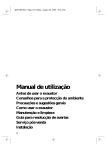
1
AZIENDA CERTIFICATA ISO 9001
"
RE USO
A
'
N D
EG ALE
S
ON NU
E
I C MA
TH
S
"
T
A
A
EG TO TE
TH DED
PR SER TEN
E
U
UR AN
N
L'I SIG.
E S IS H
K
E
AL E MA AL" ER
D DL
S NU US
A
A
E
A
ID
PLE E M THE
BIL ARIO
A
S
O
"U ER T
AM SU
A AL U
V
L
"
O
AN RLE USO
G
A
TENREG L DE R O
T
A
EN NU REGA O"
A
NT E US
"M
E
D
R
VO AL TE
FA NU TEN
A U
"M SR.
AO
CALDAIA MURALE A GAS TERMO - ALTO RENDIMENTO - MODULANTE
WALL-HUNG GAS BOILER FOR HEATING - HIGH EFFICIENCY - MODULATING
CALDERA MURAL A GAS PARA CALEFACCIÓN - ALTO RENDIMIENTO - MODULANTE
CALDEIRA DE PAREDE A GÁS PARA CALEFACÇÃO - ALTO RENDIMENTO - MODULANTE
20 N MS W TOP U/IT
MANUALE DI
INSTALLAZIONE E
MANUTENZIONE
INSTALLATION
AND MAINTENANCE
MANUAL
MANUAL PARA
LA INSTALACIÓN Y
EL MANTENIMIENTO
MANUAL DE
INSTALAÇÃO E
MANUTENÇÃO
ENGLISH
GB
Read carefully all warning and instructions contained in this manual at they give important
safety instructions regarding installation and maintenance. Keep this manual for future
reference.
Installation must be carried out by qualified personnel who will be responsible for respecting
existing safety regulations.
26
INDEX
PAGE
GENERAL INSTRUCTIONS ______________________________________________27
DESCRIPTION _________________________________________________________28
MAIN COMPONENTS _________________________________________________29
DIMENSIONS_________________________________________________________30
TECHNICAL FEATURES _________________________________________________30
GAS - NOZZLE CALIBRATION ___________________________________________31
ELECTRICAL CONNECTIONS - WIRING DIAGRAMS ________________________32
MALFUNCTIONS AND ADJUSTMENTS ___________________________________36
WATER CONNECTION _________________________________________________37
WATER CIRCUIT _______________________________________________________38
INSTALLATION ________________________________________________________39
START-UP ____________________________________________________________39
FLUE EXHAUST CONNECTION __________________________________________40
FLUE EXHAUST INSTALLATION __________________________________________41
ADJUSTMENTS _______________________________________________________42
SWITCHING OFF ______________________________________________________43
MAINTENANCE_______________________________________________________43
OPERATION WITH DIFFERENT TYPES OF GAS _____________________________45
FAULT-FINDING CHART ________________________________________________46
Congratulations...
......on an excellent choice. We thank you for the preference accorded to our products.
LAMBORGHINI CALORECLIMA has been actively present in Italy and throughout the world since
1959 with a widespread network of agents and concessionary agents to constantly guarantee the
presence of our product on the market.
Alongside this is the support of a technical service, “LAMBORGHINI SERVICE”, which is entrusted
with the qualified servicing of the product.
For the installation and positioning of the boiler:
CAREFULLY OBSERVE THE LOCAL REGULATIONS IN FORCE
27
GENERAL INSTRUCTIONS
● This booklet constitutes an integral and essential part of the product.
Read carefully the instructions contained in this booklet as they provide important directions regarding the
safety of installation, use and maintenance. Preserve this booklet with care for any further consultation.
The installation of the boiler must be carried out in compliance with current regulations, according to the
instructions of the manufacturer and by qualified personnel. An incorrect installation can cause injury or
damage to persons, animals and objects, for which the manufacturer cannot be held responsible.
● After removing the packaging materials, check the content integrity. In case of doubt, do not use the unit
and contact the supplier. The packaging material (wooden crates, nails, clips, plastic bags, foam, etc.)
must not be left within reach of children as they are potential sources of danger.
● This boiler is designed to heat water to a temperature below boiling (atmospheric pressure). It must be
connected to a heating system compatible with its performances and output.
● This appliance should be destined only for the use for which it has been expressly envisaged. Any other
use is to be considered improper and therefore dangerous. The manufacturer cannot be considered
responsible for any damages caused from improper, erroneous or unreasonable use.
ALL INSTALLATION, MAINTENANCE AND GAS CONVERSION OPERATIONS MUST BE CARRIED OUT BY
AUTHORISED SKILLED TECHNICIANS.
TO ENSURE THAT BOILER IS INSTALLED CORRECTLY AND THAT IT FUNCTIONS PROPERLY, WE RECOMMEND
THAT ONLY LAMBORGHINI ACCESSORIES AND SPARE PARTS BE USED.
ON NOTICING THE SMELL OF GAS DO NOT TOUCH ANY ELECTRIC SWITCH. OPEN DOORS AND WINDOWS. SHUT OFF THE GAS COCKS.
INSTALL THE BOILER ON WALLS WHICH ARE AS WIDE AS OR WIDER THAN THE BOILER ITSELF.
28
DESCRIPTION
These boilers are fully automatic and gas control is effected by an electronic control unit having the following
characteristics:
-
continuous modulation mode on both circuits;
possibility to adjust the heating output;
possibility to adjust the slow ignition;
XILO T models are equipped with:
-
no-water pressure switch;
total safety thermostat;
high efficiency bi-thermal flue gas exchanger;
Hot water plate exchanger.
XILO T 20 N MS W TOP
Equipped with electronic control unit for automatic ignition and ionization electrode flame control.
To ensure safe operation, the electric fan is controlled by a pressure switch.
Flue gas exhaust can be made by means of the following:
-
a flue pipe concentric with the air intake pipe;
a double pipe, one for flue gas exhaust and the other for combustion air intake.
29
MAIN COMPONENTS
XILO T 20 N MS W TOP
Fume analysis points
1 24
2
5
8
4
7
6
16
9
15
10
3
11
14 13
21
22
23
12
17
20 19 18
LEGEND
1
2
3
4
5
6
7
8
9
10
Fumes pressure switch
Fan
Heating sensor
Total safety thermostat
Exchanger
Burner
Ignition electrodes
Control electrode
Automatic air bleed valve
Safety valve
11
12
13
14
15
16
17
18
19
Circulator
Filling cock
Gas valve
Modulating coil
Gas pressure reading point
Expansion tank
Thermohydrometer
Malfunction warning light
ON/OFF warning light
20
21
22
23
24
Lock-out warning light
Fixed knob
Function selector
Heating adjustment
potentiometer
Taken combustion test
30
DIMENSIONS mm
XILO T 20 N MS W TOP
100
Max. 3000
100
220
Max. 3000
770
105
160
440
330
TECHNICAL FEATURES
Thermal capacity
MODEL
Output
Input
Input
Output
kW kcal/h kW kcal/h kW kcal/h kW kcal/h
XILO T 20 MS
W TOP
26
22.360
24
Connections
Min. thermal capacity
20640 12,1 10406 10,7
9202
Boiler version:
type B22-C12-C32-C42-C52-C62-C82
Category:
Cl NOx :
II 2H3+
2
Main system
Supply Return Gas
Ø
Ø
Ø
3/4”
3/4”
3/4”
Cold water
inlet
Operating
pressure
max.
Ø
Bar
lt
kg
1/2”
3
8
35
Max. water temperature 90°C
Rated gas pressure:
G20 20 mbar
G30 28-30 mbar/G31 37 mbar
CIRCULATING PUMP FEATURES
System delivery/pressure
Residual
pressure
Prevalenza residua
mbar
mbar
Expan- Weight
sion
tank
600
500
400
300
200
100
300 400 500 600 700 800 900 1000 1100 1200 1300 1400 1500
Portata (l/h)
Delivery
(l/h)
31
GAS - NOZZLE CALIBRATION
The boilers leave the factory calibrated and ready to operate with G20 (Natural gas) and G30/G31 (LPG).
For proper calibration, see the table below:
Gas type
G20 20 mbar
(Natural gas)
G30 28-30 mbar
(LPG)
G31 37 mbar
(LPG)
Jets pressure mbar
min.
max.
m3/h
Burner
jets
Ø mm.
1,9
11,4
2,7
1,25
8.550
4,6
24,4
0,8
0,77
29.330
6,9
32,4
1
0,77
22.360
XILO T 20 N MS
BURNER PRESSURE CURVES - OUTPUT
XILO T 20 N MS
Burner pressure intake
Slow ignition adjustment
3 mbar G20 (Natural Gas)
7,5 mbar G30/G31 (LPG)
Delivery
L.C.V.
kcal/h
32
ELECTRICAL CONNECTIONS - WIRING DIAGRAMS
The boiler must be connected to an earthed, single-phase 230V-50 Hz mains supply by means of a three-wire
cable, ensuring that connections to the PHASE and NEUTRAL terminals are made correctly.
A bipolar switch must be used with contacts opening to at least 3 mm.
The power lead must only be replaced by another with the following characteristics: “HAR H05 VV-F” 3 X 1.00
mm2. (You are strongly advised to use original LAMBORGHINI accessories and spare parts only).
Installation must be made in compliance with safety REGULATIONS IN FORCE.
Grounde connections are compulsory. Connect the boiler to an efficient grounding system.
Voltage
Absorbed power
kW
MS
0,150
Frequency
V
Hz
230
50
Protection
index
Noise level
dB (A)
MS
46
IP
X 4D
To gain access to the electrical panel which houses the power supply terminal block and any connection to a
room thermostat, proceed as follows:
● Disconnect the boiler power
supply
● Undo the two grating screws
(fig. 1)
● Undo the two jacket fixing
screws (fig. 2)
● Raise the jacket and then pull it
towards you (fig. 3)
● To access electrical and electronic
parts loosen screws A and pull
the entire panel outwards (fig.
4). Tilt downwards and undo the
screws B on the cover C
fig.3
fig.1
fig.2
fig.4
fig.5
c
A
B
A
33
ASSEMBLY DIAGRAM XILO T 20 N MS W TOP - card code 4.56035.0
EA
VG
VN
CiR
Resist.
1 kohm
TST
VG1
EC
J3
J4
J12
L
N
J1
F
MODULATOR
PS
TA
J14
L1
J8
PA
J9
J15
TL (BASSA TEMP.)
BM
J6
SR
JP3
JP1
JP4
RLA
MP
JUMPER TO BE CUT
IF LIMIT THERMOSTAT
IS REQUIRED
JP5
JP2
+
S
J10
R max.
J13
PANEL
CONNECTION
3
Lock-out warning light
2
1
ON/OFF warning light
Malfunction warning light
LEGEND
BM
CiR
EA
EC
F
JP1
JP3
JP4
JP5
JP6
Modulating coil
Heating circulator
Ignition electrode
Control electrode
Fuse 2(A)
Methane/LPG selector
Post-circulation selector
Ignition limiting selector
Jumper to be cut for low temperature
Mono-thermal/bi-thermal switch
L
N
PA
PS
RLA
Rmax.
SR
TA
TL
TST
Phase 230 V 50 Hz
Neutral
Air pressure switch
No-water pressure switch
Slow ignition power adjustment
Heating max. power adjustment
Heating sensor
Room thermostat (if any)
Limit thermostat (if any)
Safety thermostat
Warning: One of the two gas valves only, VG or VG1, is fitted on the boiler.
VG
VG1
VN
1
2
3
Gas valve SIT 837
Gas valve Honeywell
VK 4105M
Fan
Heating potentiometer
Selector:
Off
Winter
Reset
Test
Fixed knob
34
ASSEMBLY DIAGRAM XILO T 20 N MS W TOP - card code 4.55828.0
EA
TST
CiR
Resist.
1 kohm
VN
VG
J4
J3
EC
J12
L
N
J1
F
MODULATOR
PS
J14
L1
J8
J9
FC
TA
J15
TL
BM
J6
SR
JUMPER TO BE CUT
IF LIMIT THERMOSTAT
IS REQUIRED
JP3
JP1
JP4
RLA
MP
+
S
JP5 (BASSA TEMP.)
J10
Rmax.
J13
PANEL
CONNECTION
3
Lock-out warning light
2
1
ON/OFF warning light
Malfunction warning light
LEGEND
BM
CiR
EA
EC
F
JP1
JP3
JP4
JP5
Modulating coil
Heating circulator
Ignition electrode
Control electrode
Fuse 2(A)
Methane/LPG selector
Post-circulation selector
Ignition limiting selector
Jumper to be cut for low temperature
L
N
PA
PS
RLA
Rmax.
SR
TA
TL
Phase 230 V 50 Hz
Neutral
Air pressure switch
No-water pressure switch
Slow ignition power adjustment
Heating max. power adjustment
Heating sensor
Room thermostat (if any)
Limit thermostat (if any)
TST
VG
VN
1
2
3
Safety thermostat
Gas valve
Fan
Heating potentiometer
Selector:
Off
Winter
Reset
Test
Fixed knob
35
ASSEMBLY DIAGRAM XILO T 20 N MS W TOP - card code 4.56040.0
VG
EA
CiR
VG1
EC
J12
J4
J3
Resist.
1kohm
TST
VN
L
N
J1
F
MODULATOR
PS
J14
L1
J8
J9
FC
TA
JP6 JP7
J15
TL
BM
J6
SR
JUMPER TO BE CUT
IF LIMIT THERMOSTAT
IS REQUIRED
JP3
JP1
JP4
RLA
MP
+
S
JP5 (BASSA TEMP.)
J10
Rmax.
J13
PANEL
CONNECTION
3
Lock-out warning light
2
1
ON/OFF warning light Malfunction warning light
LEGEND
BM
CiR
EA
EC
F
JP1
JP3
JP4
JP5
JP6
JP7
Modulating coil
Heating circulator
Ignition electrode
Control electrode
Fuse 2(A)
Methane/LPG selector
Post-circulation selector
Ignition limiting selector
Jumper to be cut for low temperature
Mono-thermal/bi-thermal switch
Gas valve switch
L
N
PA
PS
RLA
Rmax.
SR
TA
TL
TST
VG
Phase 230 V 50 Hz
Neutral
Air pressure switch
No-water pressure switch
Slow ignition power adjustment
Heating max. power adjustment
Heating sensor
Room thermostat (if any)
Limit thermostat (if any)
Safety thermostat
Gas valve SIT 837
Warning: One of the two gas valves only, VG or VG1, is fitted on the boiler.
VG1
VN
1
2
3
Gas valve Honeywell
VK 4105M
Fan
Heating potentiometer
Selector:
Off
Winter
Reset
Test
Fixed knob
36
MULFUNCTIONS AND ADJUSTMENTS
A
B
Constant light:
Ignition shutdown
Fast flashing light:
TST shutdown
Constant light: No water
Fast flashing light: Sensor fault
Slowly flashing light:
Air pressure switch (MS)
Should the boiler shut down it must be reset by rotating functions selector switch to position A.
B: see TEST functions at “Gas pressure adjustments with Honeywell VK 4105 valve”
Legend:
On
Off
JP1
G30/G30
LPG
G20
Natural Gas
JP3
(post.circ. off)
heating
post.circ.
on 2,5 min.
JP4
Heating timer off
heating timer on 2,5 min.
JP5
Resistor jumper cut, floor heating temp. set to 30/40°C.
Resistor jumper uncut, temperature 35/80°C
JP6
cards only:
4.56035.0
4.56040.0
RLA
Increase
Present: bi-thermal function
Absent (cut): mono-thermal function
Slow ignition adjustment
R max. Max. heating power adjustment
Increase
37
WATER CONNECTION
Fit the supporting hooks and attach the assembly template, moving it up to the wall; fit all the pipes, starting
with the end pipe fittings already mounted on the template: system supply, system return, cold water, hot water,
any gas pipes and electric mains leads with room thermostat.
Once the pipes have been fitted, the end pipe fittings can be removed and ordinary caps fitted, ready for
hydraulic tests to be carried out. The template can be removed or, if left in place, will be embedded in the wall
once finishing operations have been completed (plaster and tiles); only the two supporting hooks will protrude
from the wall, as well as an opening for the connections. Attach the boiler to the hooks through the holes at the
back of the frame, pushing it up against the finished wall. Make the necessary hydraulic connections.
ADVICE AND SUGGESTIONS ON PREVENTING SYSTEM VIBRATION AND NOISE.
-
Do not use pipes of reduced diameter.
Do not use low-radius elbows or fittings that significantly reduce cross-section.
Hot-flushing of the system is recommended in order to eliminate any impurities from the piping and radiators (especially oil and grease) which might damage the circulator.
440
384
28
13,5
28
GS
F
AE
M
R
GS
M AE
G
F
R
NOTE: Provide female water connections.
98
130,5
220
278
98
342
440
770
Gas Ø 1/2” - Ø 3/4”
(see cock supplied with the boiler)
Boiler water supply Ø 1/2” (cold)
Electrical supply
System delivery Ø 3/4”
System return Ø 3/4”
Holding hooks Ø10 mm.
12
G
744,5
LEGEND
38
WATER CIRCUIT
XILO T 20 N MS W TOP
Fume analysis points
11
12
1
10
3
1009DIS1360
9
14
13
8
7
15
4
2
A
6
B
C
5
D
LEGEND
A
B
C
D
1
2
3
4
5
6
System delivery
Gas
Cold water inlet
System return
Exchanger
Modulator coil
Heating sensor
Gas valve
Filling cock
Safety valve
7
8
9
10
11
12
13
14
15
No-water pressure switch
Circulator
Burner
Expansion tank
Fumes pressure switch
Fan
Automatic air bleed valve
Total safety thermostat
By-Pass (if any)
39
INSTALLATION
To be carried out by qualified personnel.
The installation must be in compliance with the stipulations of the law regarding the evacuation of combustion
materials according to the REGULATIONS IN FORCE.
The gas fume evacuation must be effected with a pipe of a diameter not less than that required by the boiler
and it must be connected to a flue pipe suitable for the capacity of the installation.
For connection of appliances to smoke conduits:
a) they must be easy to dismantle;
b) they must be sealed and of a material able to resist the products of
combustion and their possible condensation;
c) they must not have regulation devices (gate valves). If such devices are
already in operation they must be eliminated;
d) the connection itself must not protrude inside the flue pipe but stop before the internal
face of the same.
GAS CONNECTION
Carry out the gas connection in accordance with the regulations in force.
The boiler must be connected to the installation with a rigid metal pipe or a flexible stainless steel pipe with
continuous wall of the approved type. The flexible corrugated metal pipes must be installed in such a way that
their length, in a state of maximum extension, is not greater than 2000 mm. The boilers are calibrated and
tested to function with G20 (Natural Gas) and G30/G31 (LPG), category II 2H3+, with rated pressures of 20
mbar, 28/30 mbar and 37 mbar respectively.
PUTTING THE BOILER INTO SERVICE
● Proceed with the clearing out of air.
● Check that there are no gas leaks (use a soapy solution or equivalent product).
START-UP
SYSTEM FILLING
Open the feeding tap slowly until the system reaches a working pressure (indicated on the hydrometer) of 1.5
bar, then close it. Check that the automatic air bleed valve, on the circulator, has its cap loosened; run the
circulator repeatedly to eliminate any air in the circuit.
IGNITION
Open the gas tap and turn the selector switch to the desired position. The burner will ignite automatically.
Should the unit fail to ignite see if the lock-out indicator is on. If it is, turn the selector switch to RESET so that
the boiler repeats the ignition sequence. Then adjust heating and hot water temperature as desired via the
appropriate controls.
40
FLUE EXHAUST CONNECTION
CONNECTION TO THE CHIMNEY - VERSION XILO T 20 N MS W TOP
The boiler is for combustion in a sealed chamber and does not require any special ventilation, it can also be
located in small rooms, lumber-rooms, laboratories. In addition, there are various possibilities for combustion fume
evacuation and external air intake; basically the boiler is designed for two types of fume evacuation/air intake:
● fume evacuation/air intake concentric pipes system,
● fume evacuation/air intake double pipes system.
In this way it is possible, by using suitable kits, to connect the boiler to concentric flues, ventilating flues,
separate flues, etc. Some possible solutions are indicated below.
FUME EVACUATION/AIR INTAKE
1
2
3
4
5
6
7
8
Concentric flue pipe, from the roof C32
Concentric flue pipe, from the terrace C32
Double flue pipe from separate flues C42
Concentric flue pipe, connected to concentric flues C42
Concentric flue pipe, from an external wall C12
Double flue pipe from the terrace C52
Double flue pipe from single flue C82
Double flue pipe C62
1
66
8
7
2
3
4
3
4
55
For positioning and for distances of draught terminals from windows, doors, etc. see regulations in force.
41
FLUE EXHAUST INSTALLATION
CONCENTRIC FLUE PIPE
Fit the concentric elbow pipe positioning it on the desired direction and insert on it the sealing gasket. Then
fit the appropriate diaphragm (see table below).
Fit the air intake and flue exhaust pipes, observing the distances indicated on the installation scheme. The flue
pipe should slope slightly outward.
Max. 3000
100
220
Ø100
100
Max. 3000
160
105
FLUE
EXHAUST PIPE
SCARICO
770
Diaframma
Air diaphragm
aria
440
DOUBLE FLUE PIPE
330
CONCENTRIC FLUE PIPE
Max. length
Over 1 m
0,5 ÷ 1 m
max. 3 m
Diaphr.
Diaphr.
Ø 78 mm
Ø 87 mm
DOUBLE FLUE PIPE
length m
0,5 ÷ 10 10 ÷ 20
Diaphr.
Diaphr.
Ø 47 mm Ø 50 mm
20 ÷ 30
NO
Maximum length of CONCENTRIC FLUE PIPE 3 m
Maximum length of DOUBLE FLUE PIPE
(Intake + Exhaust) 20 m
1009DIS1349
Installing an elbow to connect the boiler to the chimney will cause a
drop in pressure.
The values set out in the table below indicate the necessary modifications to the length of the linear pipes.
250
97
CONCENTRIC FLUE PIPE
ELBOW FITTED
AT 90°
1m
ELBOW FITTED
AT 45°
0,5 m
SEPARATE INTAKE/EXHAUST
0,6 m
0,3 m
TYPE OF INSTALLATION
** Air intake Ø 80
ATTENTION: Use only air intake/ fume evacuation kits produced by Lamborghini Caloreclima.
42
GAS PRESSURE ADJUSTMENTS WITH HONEYWELL VK 4105 VALVE
All boilers are tested and calibrated in the factory. At first ignition it is necessary to check and set up the boiler
to adapt it to the system characteristics. The gas pressure at the burner must be checked through the pressure
plug placed on the pipe coming out from the gas valve and by using a water column pressure gauge or a
micro-manometer. The values must be those indicated in the specific table. When all calibrations have been
completed, close and seal the pressure plug used. Calibration of the slow ignition is electronically done and
is adjustable (for optimising and for gas type conversion) by the trimmer RLA on the electronic board. The
necessary thermal output for the heating system can be regulated by acting on the trimmer R.MAX.
By removing the JP4 bridge, the waiting time for boiler restarting can be varied, after its stop when reaching
the temperature selected on the heating potentiometer. (bridge off: 2,5 minutes)
MODULATION MAXIMUM PRESSURE ADJUSTMENT
● remove the protecting cover G
● place the “function selector” on TEST position
● tighten (to increase) or untighten (to decrease) the adjustment bolt H
MINIMUM PRESSURE ADJUSTMENT
After the maximum pressure adjustment has been completed proceed with the following operations:
● disconnect the power wire (12 V) from the modulation coil
● tighten (to increase) or untighten (to decrease) the adjustment bolt I
● connect again the modulation coil power wire (12 V) (“function selector” must always be on TEST position)
● replace the protecting cover G
Once adjustments have been effected, replace “function selector” on Summer or Winter.
G
I
H
Burner pressure
intake
JP1
JP3
JP5
JP4
RLA
R max.
Adjustment trimmer RLA
Adjustment trimmer R. MAX
Note: “Function selector” places on “TEST” only for combustion test. This function stops gas pressure on
maximum output for 15 minutes.
For this calibration it is necessary to use a water column pressure gauge connected to the pressure
plug.
43
SWITCHING OFF
PROLONGED SWITCHING OFF
If the boiler should remain inactive at length close the gas cock and cut electrical power supply to the appliance.
TEMPORARY SWITCHING ON/OFF
Proceed in one of the following ways:
● use the room thermostat;
● use the adjustment potentiometers (on the instrument panel);
NOTE: with a new boiler or after a long period of inactivity,
one can check for the locking of the circulating
pump. In this case it is necessary to unscrew the
front stopper and make the motor shaft rotate with
a screwdriver.
MAINTENANCE
To ensure long-lasting product functionality and efficiency within the limits prescribed by the laws and standards
in force, the unit must undergo regular maintenance.
Frequency of inspection depends on the specific conditions of installation and use but it is advisable to have
the unit checked once a year by authorised Lamborghini Service personnel. Only properly qualified personnel
with specific knowledge in the field of safety, efficiency, environmental hygiene and combustion may carry out
work on the unit. To ensure proper maintenance it is also required that such personnel be fully updated on the
constructive and functional characteristics of the boiler.
Should work or maintenance be carried out on any structures situated near fume ducts and/or fume discharge
devices and their accessories always switch off the boiler and, when work is over, have its efficiency checked
by qualified personnel
IMPORTANT: before doing any cleaning or maintenance work on the unit switch off the electrical power supply
via the switch on the boiler itself. Shut off the gas supply by closing the tap on the boiler. The above stated,
work generally involves the following:
44
-
removal of any oxidation from burners
removal of any encrustation from heat exchangers
checking and general cleaning of fan (mod. MS)
checking connections between the various air/fume pipes
general pipe cleaning
checking general external appearance of boiler
checking for proper ignition, shutdown and operation of both hot water and heating functions
checking for proper seal on gas/water fittings and pipes.
checking gas consumption at minimum and maximum power
checking position of ignition electrode
checking position of detection electrode
checking combustion and efficiency parameters
checking the no-gas safety device
water system pressure
expansion tank efficiency
checking for proper operation of safety and adjustment thermostats
checking for proper circulation pump operation
checking that no gas whatsoever leaks from the unit and no combustion gas leaks from the down-draught
diverter or the boiler-flue connection.
checking gas flow rate.
Do not clean the unit and/or its component parts with easily inflammable substances (e.g. petrol, alcohol etc.)
Do not clean panelling, painted and plastic parts with paint diluents.
Clean the panelling with soapy water only.
If a room thermostat is installed we recommend our chronothermostat CLASS PIU’ which, in addition to guaranteeing the comfort of a precise regulation of temperature, offers a notable range of heating programmes;
alternatively use a programming digital timer.
ATTENTION. The room thermostat with 230 V mains supply must be connected to the earth terminal, or use
a class II room thermostat.
Chronothermostat CLASS PIU’ (accessory)
45
OPERATION WITH DIFFERENT TYPES OF GAS
CONVERSION FROM NATURAL GAS TO LIQUID GAS
The boiler is factory-set for G20 (Natural Gas) or G30/G31(LPG) operation, as mentioned on the Technical
Nameplate and on the apparatus packaging. In the event the heater shall be operated using a different gas
from that conceived by factory setting, a special kit has to be installed, which is to be ordered separately.
To perform conversion, act as follows:
- Remove the cover and open the tight chamber (for model MS)
- Unscrew the fastening screws (1) and remove the burner (2) (fig. 1)
- Replace the burner nozzles (3) with those supplied with the transformation kit, making sure that the
relevant diameter corresponds to that reported in the table shown below. Insert the sealing rings
- Reassemble the burner
- Close the tight chamber checking proper positioning of seal gaskets (for model MS)
Then act as follows:
For transformation from G20 (Natural Gas) to G30/G31 (LPG):
- Insert the gas diaphram (fig. 2 )
- Move jumper JP1 to ON position (fig. 3)
- Disconnect the pressure regulator by screwing tight the nut (H) (page 42) and adjust minimum pressure to
the value reported in the table shown below by acting on the screw (I) (page 42)
- If necessary, adjust trimmers RLA and R.MAX according to the system features
- Seal the regulator by applying the cover ( G )
For transformation from G30/G31(LPG) to
G20 (Natural Gas):
- Remove the gas diaphram
fig. 1
Gasket
- Move jumper JP1 to OFF position (fig. 3)
Ø
Gas Diaphragm
- Regulate the pressure (maximum and minimum values) of the burner according to the
Gas Valve
values reported in the table shown below,
by acting on the nut (H) and on the screw
(I) respectively, as described in paragraph
‘ADJUSTMENTS’ (page 42)
- If necessary, adjust trimmers RLA and R.MAX
Legend:
according to the system features
- To confirm transformation, apply the adheOn
Off
sive plate supplied with the transformation
G20
JP1 G30/G31
KIT on the Technical Nameplate reporting the
LPG
Natural Gas
information featuring the gas, and according
fig. 3
fig. 2
to the factory-setting.
Gas type
G20-20mbar
(Natural Gas)
G30-28/30mbar
(LPG)
G31-37mbar
(LPG)
Jets pressure mbar
Classe Gas Diaphragm (H)
MS
NOx
MS
Ø
min.
max.
Gas delivery
m3/h
1,9
11,4
2,7
1,25
8.550
2
-
4,6
24,4
0,8
0,77
29.330
2
4,5
6,9
32,4
1
0,77
22.360
2
4,5
XILO T 20 N MS
Burner
jets
Ø mm.
kcal/h
L.C.V.
46
FAULT-FINDING CHART
FAULT
CAUSE
REMEDY
1 NO IGNITION
A. Gas cock closed
B. Boiler locked out
C. No flame detection
D. No ignition spark
E. Air inside pipes
F. Safety thermostat intervention
G. Water not circulating
H. Boiler water temperature higher than
figure set on the adjustment thermostat
A.
B.
C.
D.
E.
F.
G.
2 CRACKLING
IGNITION
A. Irregular flame
B. Insufficient or wrongly adjusted
gas delivery
A. Call technical service
B. Call technical service
3 SMELL OF GAS
A. Leak in pipes circuit (inside and
outside boiler)
A. Check the external pipes
Check the internal pipes
Call technical service
Open gas cock
Reset by pressing
Neutral and phase inverted
Call technical service
Repeat ignition
Press reset push-button
Adjust boiler pressure and check
circulator
H. Adjust thermostat setting on desired
temperature.
A. Flue cross-section or height with
4 MELL OF
joint not suitable for the boiler
UNBURNT GAS
AND BAD BUR- B. Excessive gas consumption NER COMBUcombustion is imperfect
C. Flames tend to detach
STION
D. Flames have yellow tips
A. Replace unsuitable components
B. Adjust gas delivery
C. Check/adjust gas valve
pressure stabilizer
D. Check that air volutes and Venturi
cones of the burner are clean
If items A-B-C-D have been checked
with negative result call technical
service
5 CONDENSATION A. Flue cross-section or height not
suitable (excessive size)
IN THE BOILER
B. Boiler operating at low temperature
A. Replace unsuitable components.
B. Adjust boiler thermostat at a higher
temperature and check if air intake
pipe/flue exhaust connection is
correct.
6 COLD RADIATORS IN
WINTER
A. Function selector on summer position
B. Room thermostat set too low or faulty
C. System or radiators closed
D. Circulator blocked
A. Place it in winter position
B. Adjust thermostat at a higher
temperature or replace it.
C. Check if system gate valves and
radiator cocks are opened.
If item C has been checked with
negative result call technical service
D. Unblock with a screwdriver and
check electrical supply
BRUCIATORI
CALDAIE MURALI E TERRA A GAS
GRUPPI TERMICI IN GHISA E IN ACCIAIO
GENERATORI DI ARIA CALDA
TRATTAMENTO ACQUA
CONDIZIONAMENTO
92
Le illustrazioni e i dati riportati sono indicativi e non impegnano. La LAMBORGHINI si riserva il diritto di apportare senza
obbligo di preavviso tutte le modifiche che ritiene più opportuno per l'evoluzione del prodotto.
The illustrations and data given are indicative and are not binding on the manufacturer. LAMBORGHINI reserves the right to
make those changes, considered necessary, for the improvement of the product without forwaming the customer.
Las ilustraciones y los datos son indicativos y no comprometen. LAMBORGHINI se reserva el derecho de realizar sin preaviso
todas las modificaciones que estime oportuno para la evolución del producto.
As ilustrações e os dados existentes são indicativos e não compromissivos. A LAMBORGHINI reserva-se o direito de efectuar,
sem a obrigação de pré-aviso, todas as modificações que considerar necessárias para a melhoria do produto.
LAMBORGHINI CALOR S.p.A.
VIA STATALE, 342
44040 DOSSO (FERRARA)
ITALIA
TEL. ITALIA 0532/359811 - EXPORT 0532/359913
FAX ITALIA 0532/359952 - EXPORT 0532/359947
Cod. 97.50783.0 05/2006
1
AZIENDA CERTIFICATA ISO 9001
IT
CALDAIA MURALE A GAS TERMO
ALTO RENDIMENTO - MODULANTE
MANUALE PER L‘UTENTE
GB
WALL-HUNG GAS BOILER FOR HEATING
FOR HIGH EFFICIENCY - MODULATING
USER MANUAL
ES
CALDERA MURAL A GAS PARA CALEFACCIÓN
ALTO RENDIMIENTO - MODULANTE
MANUAL PARA EL USUARIO
PT
CALDEIRA DE PAREDE A GÁS PARA CALEFACÇÃO
ALTO RENDIMIENTO - MODULANTE
MANUAL DO UTENTE
2
Alla cortese attenzione del sig. INSTALLATORE:
Consegnare il presente manuale d’uso all’UTENTE
9
For the attention of the INSTALLATION TECHNICIAN:
make sure that this manual is handed over to the USER
16
A la atención del sr. INSTALADOR:
Entregar el presente manual para el uso al USUARIO
23
Àtenção do Sr. INSTALADOR:
Entregue este manual de uso ao UTENTE
20 N MS W TOP U/IT
9
INDEX
PAGE
GENERAL INSTRUCTIONS ______________________________________________10
INSTRUCTION FOR THE USE ____________________________________________11
CHECKINGS AND MAINTENANCE ______________________________________12
DIMENSIONS mm _____________________________________________________13
IGNITION - OPERATION - SHUTDOWN INSTRUCTIONS ____________________14
FAULT-FINDING CHART ________________________________________________15
Dear User…
… you now own a product, result of a thorough project and of advanced construction systems,
granting you the utmost reliability, operation safety and great saving for its use.
Carefully read this manual to know all information about the appliance operation.
“LAMBORGHINI AFTER-SALE SERVICE”, is at your disposal to grant
you a QUALIFIED MAINTENANCE and a VERY PROMPT AFTER-SALE SERVICE
LAMBORGHINI CALORECLIMA
For boiler installation and location:
STRICTLY FOLLOW LOCAL SPECIFICATIONS IN FORCE.
10
GENERAL INSTRUCTIONS
●
This booklet constitutes an integral and essential part of the product and should be preserved for any
further consultation.
Read carefully the instructions contained in this booklet as they provide important directions regarding
the operation of the appliance, allowing a great saving in its use and maintenance.
●
If the appliance is sold or transferred to other people or if you move house and leave your apartment,
ensure that the manual remains with the appliance so that it can be used by the new owner.
●
This appliance should be destined only for the use for which it has been expressly envisaged.
Any other use is to be considered improper and therefore dangerous.
The manufacturer cannot be considered responsible for any damages caused from improper, erroneous
or unreasonable use.
●
Do not touch the parts of the boiler which during the operation become overheated.
These parts can be dangerous for children or inexperienced persons.
●
Do not obstruct the inlet or dissipation screens.
●
Do not make the boiler wet with splashes of water or other liquids.
●
Do not rest any object upon the boiler.
●
Use of the boiler is prohibited for children or the inexperienced.
●
Do not carry out any cleaning of the boiler with inflammable substances.
●
Do not deposit containers of inflammable substances in the location where the boiler is situated.
●
In the presence of the risk of freezing suitable provisions must be taken which are not however the concern
of the boiler manufacturer
ALL INSTALLATION, MAINTENANCE AND GAS CONVERSION OPERATIONS MUST BE CARRIED OUT BY
AUTHORISED SKILLED TECHNICIANS.
TO ENSURE THAT BOILER IS INSTALLED CORRECTLY AND THAT IT FUNCTIONS PROPERLY, WE RECOMMEND
THAT ONLY LAMBORGHINI ACCESSORIES AND SPARE PARTS BE USED.
ON NOTICING THE SMELL OF GAS DO NOT TOUCH ANY ELECTRIC SWITCH. OPEN DOORS AND WINDOWS. SHUT OFF THE GAS COCKS.
11
INSTRUCTION FOR THE USE
● In case of breakdown and/or malfunctioning of the appliance, disconnect it avoiding any attempt of repair
or direct intervention.
Call exclusively professionally qualified personnel.
Any repair must be carried out by an after-sale service centre “LAMBORGHINI SERVICE” authorised by
the manufacturing firm, and using original replacements exclusively.
Non-observance of the above could compromise the guarantee and the safety of the appliance.
In order to guarantee the efficiency of the appliance and its proper operation it is indispensible to keep
to the manufacturerís directions, by ensuring the periodical servicing of the appliance is carried out by
professionally qualified personnel.
● Check the hydraulic pressure of the installation on the hydrometer and that the indication, when the system
is cold, is within the limits set by the manufacturer: if one should find a drop in pressure request for an
inspection by qualified personnel.
● After each reopening of the gas cock wait a few minutes before restarting the boiler
● Do not leave the boiler switched on if it is not used for long time: in this case switch gas main supply,
electricity and water supply off by their own cocks and switches.
● As soon as one decides not to use the appliance further, one should take care to render innocuous those
parts liable to be potential sources of danger.
● As soon as one decides to disconnect the boiler definitively, one should ask qualified personnel to effect
the related works, then ensure that the main supplies have been disconnected.
● For the power supply to the boiler the use of adaptors, multiple sockets or extensions is not permitted.The
use of a switch as indicated by the safety regulations in force must be provided.
● The use of appliances which utilise electrical energy involve the observation of fundamental rules which are:
a)
not to touch the appliance with parts of the body which are wet or when in bare feet;
b)
not to pull electrical wires;
c)
not to expose the appliance to the atmospheric agents;
d)
not to allow use of the appliance to children or the inexperienced.
● In the case of structural work positioned near the flue pipe, turn off the boiler and at the end of the work
ensure that the efficiency of the flue exhaust is verified by qualified personnel.
● On noticing the smell of gas do not touch any electric switch.Open all doors and windows. Shut off the
gas cocks and call qualified personnel.
12
CHECKS AND MAINTENANCE
● Prima di avviare la caldaia far verificare da Personale Qualificato “LAMBORGHINI SERVICE”:
a) that the data on the information plate corresponds to that required by the gas, electrical and water
supply networks;
b) that the pipes which branch off from the boiler are lined with suitable thermally-insulated sheathing;
c) the proper functioning of the flue pipe;
d) that the comburent air flow and the fumes evacuation take place properly in accordance with the
regulations in force.
e) that correct aeration and maintenance are possible in case of installation in the furniture.
●
The transformation from a gas (methane or liquid gas) to a gas of another group, which can also be
made with the boiler installed, must be made exclusively by qualified personnel.
●
Ensure that the installer has connected the boiler safety discharge to a waste. In the case of the contrary
the intervention of the safety valves could flood the premises and the manufacturer would not be held
responsible for this.
●
Ensure that the piping of the installation is not used as an earth outlet for other installations; beyond not
being ideal for such a use it could in short bring serious damage to the other appliances connected to it.
●
Ask qualified personnel “LAMBORGHINI SERVICE” to check:
a) the internal and external tightness of the gas system;
b) that the gas delivery is that required by the boiler output;
c) that the type of gas is suitable for the boiler;
d) that the pressure of gas supply is within the values stated on the boiler plate;
e) that the gas installation is the correct size and equipped with all the safety and checking devices
prescribed by the current regulations.
●
Ask periodically to check the proper functioning and the good state of the flue exhaust.
●
Ensure that the electrical system has been confirmed by qualified personnel to be adequate for the power
required by the appliance itself.
●
The electricity supply cable must not be replaced by the user, but by qualified personnel only.
●
The electrical safety of the appliance is attained only if the same has been connected to an effective system
earthed in accordance with the current regulations. The verification of this fundamental prerequisite should
be made by qualified persons as the manufacturer will not be responsible for damage caused by the lack
of adequate earthing of the installation.
13
DIMENSIONS mm
XILO T 20 N MS W TOP
100
Max. 3000
100
220
Max. 3000
770
105
160
440
330
CONTROL PANEL AND ADJUSTMENTS
1
5
A
6
4
2
3
7
Constant light: No water
Constant light: Ignition shutdown
Fast flashing light: Sensor fault
Fast flashing light: TST shutdown
Slowly flashing light: Air pressure
switch (MS)
Should the boiler shut down it must be reset by rotating functions selector switch 6 to position A.
1
2
3
4
Lock-out warning light
ON/OFF warning light
Malfunction warning light
Heating adjustment potentiometer
5
6
7
Hot water adjustment potentiometer
Function selecto
Thermohydrometer
14
IGNITION - OPERATION - SHUTDOWN INSTRUCTIONS
IGNITION
Open the gas tap and tun the selector switch (6) to the desired position. The burner will ignite automatically.
Should ignition fail to take place check the lock-out warning light (1) and fault warning light (3) to see if they
have come on. Turn the selector (6) to the reset position A. Then rotate the selector (6) again to the desired
position. Then adjust heating temperature (4) and hot water temperature (5) as desired via the appropriate
controls.
TEMPORARY IGNITION/SHUTDOWN
Proceed as follows:
● adjust the room thermostat;
● adjust the potentiometers on the front panel (4) (5).
PROLONGED SHUTDOWN
Should the boiler remain idle for a long period close the gas tap, position the selector switch (6) at position
(0) and disconnect the electrical power supply.
SUMMER MODE
Turn the selector switch (6) to SUMMER.
Regulate the hot water potentiometer (5) to a position corresponding to desired water temperature.
WINTER MODE
Turn the selector switch (6) to WINTER.
Regulate the heating potentiometer (4) to a position that corresponds to desired heating temperature.
If a room thermostat is installed then the thermostat will keep room temperature at the set level.
Adjust the hot water potentiometer (5) to a position corresponding to desired water temperature.
WARNING: When Summer
or Winter
that the boiler is electrically powered.
mode is selected the ON indicator light comes on indicating
WARNING: Use only 2A/250VC - 5x20 rapid fuses.
15
FAULT-FINDING CHART
FAULT
CAUSE
REMEDY
1 NO IGNITION
A. Gas cock closed
B. “Lock-out” button locked
C. No flame detection
D. No ignition spark
E. Air inside pipes
F. Safety thermostat intervention
A. Open gas cock
B. Reset by pressing
C. Call technical service
D. Call technical service
E. Repeat ignition
F Wait for the temperature to drop
2 CRACKLING
IGNITION
A. Irregular flame
B. Insufficient or wrongly adjusted
gas delivery
A. Call technical service
B. Call technical service
3 SMELL OF GAS
A. Leak in pipes circuit (inside and
outside boiler)
A. Call technical service
4 MELL OF
A. Flue section or height with joint not A. Call technical service
UNBURNT GAS
B. Call technical service
suitable for the boiler
AND BAD BUR- B. E x c e s s i v e g a s c o n s u m p t i o n - C. Call technical service
NER COMBUcombustion
STION
state is imperfect
C. Flames tend to move away or have
yellow tips
5 CONDENSATION A. Flue cross-section or height not
IN THE BOILER
suitable (excessive size)
B. Boiler operating at low temperature
6 COLD RADIATORS
IN WINTER
A. Function selector on summer position
B. Room thermostat set too low or faulty
C. System or radiators closed
D. Circulator blocked
A Call technical service
B Adjust boiler thermostat at a higher
temperature.
A. Place it in winter position
B. Adjust thermostat at a higher
temperature or replace it.
C. Check if system gate valves and
radiator cocks are opened.
If item C has been checked with
negative result call technical service
D. Call technical service
BRUCIATORI
CALDAIE MURALI E TERRA A GAS
GRUPPI TERMICI IN GHISA E IN ACCIAIO
GENERATORI DI ARIA CALDA
TRATTAMENTO ACQUA
CONDIZIONAMENTO
32
Le illustrazioni e i dati riportati sono indicativi e non impegnano. La LAMBORGHINI si riserva il diritto di apportare senza
obbligo di preavviso tutte le modifiche che ritiene più opportuno per l'evoluzione del prodotto.
The illustrations and data given are indicative and are not binding on the manufacturer. LAMBORGHINI reserves the right to
make those changes, considered necessary, for the improvement of the product without forwaming the customer.
Las ilustraciones y los datos son indicativos y no comprometen. LAMBORGHINI se reserva el derecho de realizar sin preaviso
todas las modificaciones que estime oportuno para la evolución del producto.
As ilustrações e os dados existentes são indicativos e não compromissivos. A LAMBORGHINI reserva-se o direito de efectuar,
sem a obrigação de pré-aviso, todas as modificações que considerar necessárias para a melhoria do produto.
LAMBORGHINI CALOR S.p.A.
VIA STATALE, 342
44040 DOSSO (FERRARA)
ITALIA
TEL. ITALIA 0532/359811 - EXPORT 0532/359913
FAX ITALIA 0532/359952 - EXPORT 0532/359947
Cod. 97.50783.0 05/2006