1
Chapter 7 Service Configuration
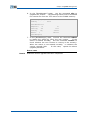
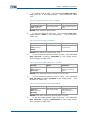
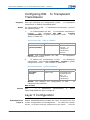
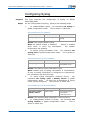
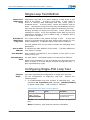
12.
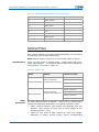
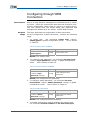
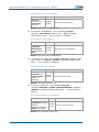
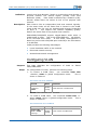
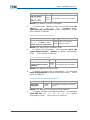
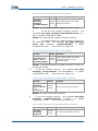
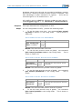
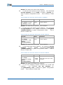
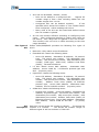
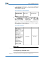
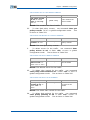
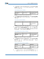
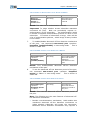
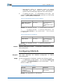
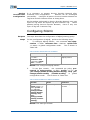
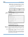
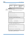
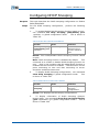
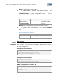
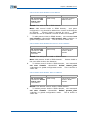
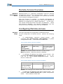
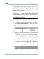
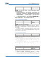
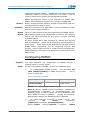
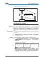
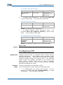
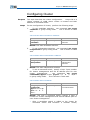
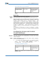
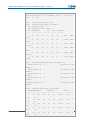
To set stp hmd5 key, use command set stp hmd5-key
{CISCO|HUAWEI}<0, 0x00. . 0-0xff. . f> in global
configuration mode. This is shown in Table 158.
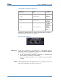
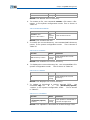
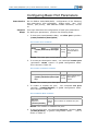
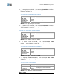
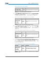
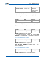
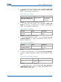
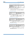
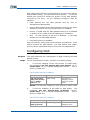
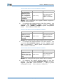
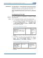
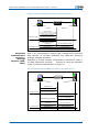
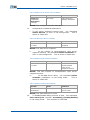
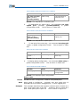
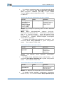
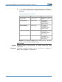
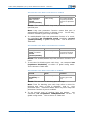
TABLE 158 SET STP HMD5 KEY PORT COMM AND
Format
Mode
Function
set stp hmd5-key
{CISCO|HUAWEI}<0,
0x00. . 0-0xff. . f>
Global
config
This sets stp hmd5 key
Result: This sets stp hmd5 key.
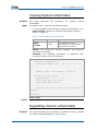
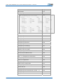
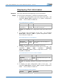
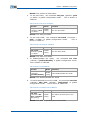
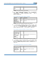
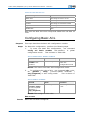
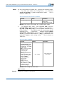
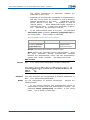
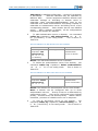
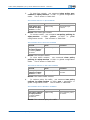
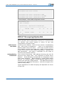
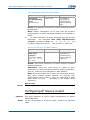
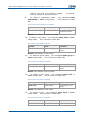
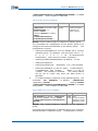
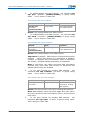
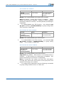
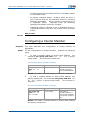
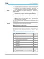
13.
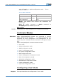
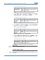
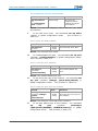
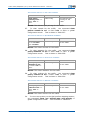
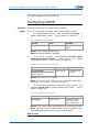
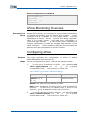
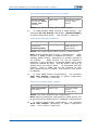
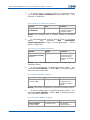
To set the maximum number of hop between any two
terminals of MST, use command set stp hopmax <1-40>
in global configuration mode. This is shown in Table 159.
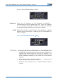
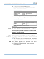
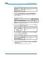
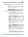
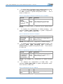
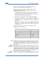
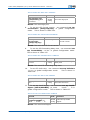
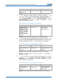
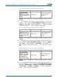
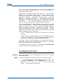
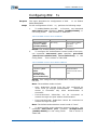
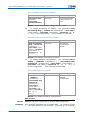
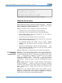
TABLE 159 SET STP HOPMAX COMM AND
Format
set stp hopmax <140>
Mode
Global
config
Function
This sets the maximum
number of hop between
any two terminal of MST
Result: This sets the maximum number of hop between any
two terminals of MST.
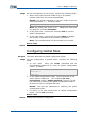
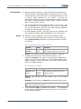
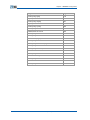
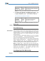
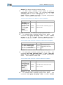
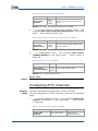
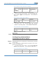
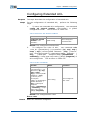
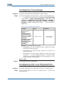
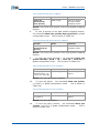
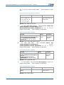
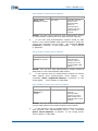
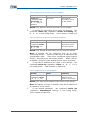
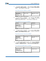
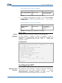
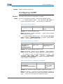
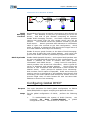
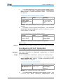
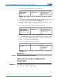
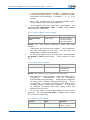
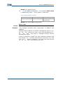
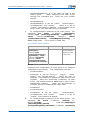
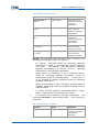
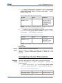
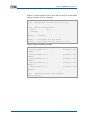
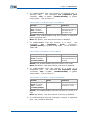
18.
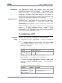
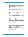
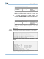
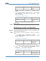
To set the bridge priority,
use command set stp
instance
<0-15>
priority
<0-61440>
in
global
configuration mode. This is shown in Table 160.
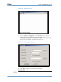
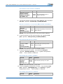
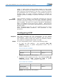
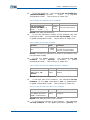
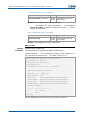
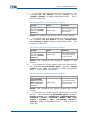
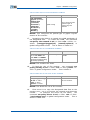
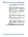
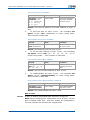
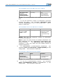
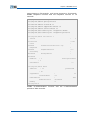
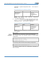
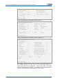
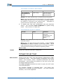
TABLE 160 SET STP INSTANCE BRIDGE PRIORITY COMMAND
Format
Mode
Function
set stp instance <015> priority <061440>
Global
config
This sets the bridge
priority
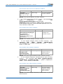
Result: This sets the bridge priority.
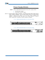
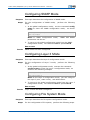
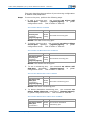
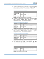
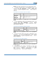
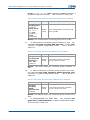
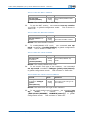
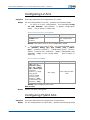
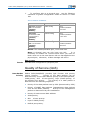
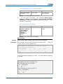
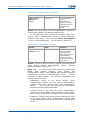
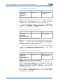
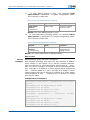
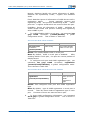
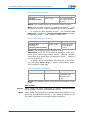
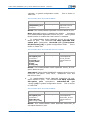
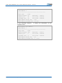
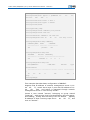
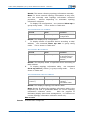
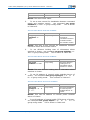
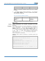
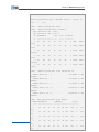
15.
To set port cost of the instance, use command set stp
instance <0-15> port <portname> cost <1-200000000>
in global configuration mode. This is shown in Table 161.
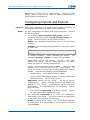
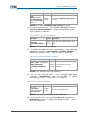
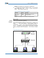
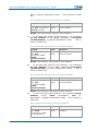
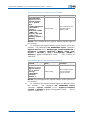
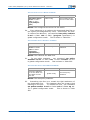
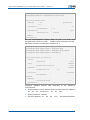
TABLE 161 SET STP INSTANCE PORT COST COMM AND
Format
Mode
Function
set stp instance <015> port <portname>
cost <1-200000000>
Global
config
This sets port cost of the
instance
Result: This sets port cost of the instance.
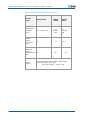
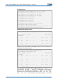
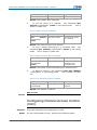
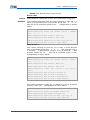
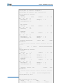
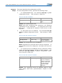
16.
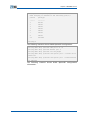
To set the port priority of the instance, use command
set stp instance <0-15> port <portname> priority <0-
Confidential and Proprietary Information of ZTE CORPORATION
115