1
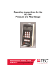
Operating Instructions for the DG-500 Pressure Gauge Operating Instructions for the DG-500 Pressure Gauge The Energy Conservatory 2801 21st Ave. S., Suite 160 Minneapolis, MN 55407 Ph.: (612) 827-1117 Fax: (612) 827-1051 www.energyconservatory.com Manual Edition January 2005 2005 The Energy Conservatory. All rights reserved. ENERGY CONSERVATORY WARRANTY EXPRESS LIMITED WARRANTY: Seller warrants that this product, under normal use and service as described in the operator’s manual, shall be free from defects in workmanship and material for a period of 24 months, or such shorter length of time as may be specified in the operator’s manual, from the date of shipment to the Customer. LIMITATION OF WARRANTY AND LIABILITY: This limited warranty set forth above is subject to the following exclusions: a) b) c) d) With respect to any repair services rendered, Seller warrants that the parts repaired or replaced will be free from defects in workmanship and material, under normal use, for a period of 90 days from the date of shipment to the Purchaser. Seller does not provide any warranty on finished goods manufactured by others. Only the original manufacturer’s warranty applies. Unless specifically authorized in a separate writing, Seller makes no warranty with respect to, and shall have no liability in connection with, any goods which are incorporated into other products or equipment by the Purchaser. All products returned under warranty shall be at the Purchaser’s risk of loss. The Purchaser is responsible for all shipping charges to return the product to The Energy Conservatory. The Energy Conservatory will be responsible for return standard ground shipping charges. The Customer may request and pay for the added cost of expedited return shipping. The foregoing warranty is in lieu of all other warranties and is subject to the conditions and limitations stated herein. NO OTHER EXPRESS OR IMPLIED WARRANTY IS PROVIDED, AND THE SELLER DISCLAIMS ANY IMPLIED WARRANTY OF FITNESS FOR PARTICULAR PURPOSE OR MERCHANTABILITY. THE EXCLUSIVE REMEDY OF THE PURCHASER FOR ANY BREACH OF WARRANTY shall be the return of the product to the factory or designated location for repair or replacement, or, at the option of The Energy Conservatory, refund of the purchase price. The Energy Conservatory’s maximum liability for any and all losses, injuries or damages (regardless of whether such claims are based on contract, negligence, strict liability or other tort) shall be the purchase price paid for the products. IN NO EVENT SHALL THE SELLER BE LIABLE FOR ANY SPECIAL, INCIDENTAL OR CONSEQUENTIAL DAMAGES. The Energy Conservatory shall not be responsible for installation, dismantling, reassembly or reinstallation costs or charges. No action, regardless of form, may be brought against the Seller more than one year after the cause of action has accrued. The Customer is deemed to have accepted the terms of this Limitation of Warranty and Liability, which contains the complete and exclusive limited warranty of the Seller. This Limitation of Warranty and Liability may not be amended or modified, nor may any of its terms be waived except by a writing signed by an authorized representative of the Seller. TO ARRANGE A REPAIR: Please call The Energy Conservatory at 612-827-1117 before sending any product back for repair or to inquire about warranty coverage. All products returned for repair should include a return shipping address, name and phone number of a contact person concerning this repair, and the purchase date of the equipment. Table of Contents CHAPTER 1 FEATURE SUMMARY 1.1 Feature List 1 1 1.1.a Pressure Measurements: 1 1.1.b Auto Zeroing: 1 1.1.c Time Averaging: 1 1.1.d Air Velocity Measurements: 1 1.1.e Display “HOLD”: 1 1.1.f Data Logging Pressure Measurements: 1 1.2 Overview of Gauge Operating Modes 2 1.3 Gauge Face 2 1.4 Gauge Buttons 3 1.5 Input/Output Ports on the DG-500 3 1.5.a Serial Communication Port: 3 1.5.b AC Power Input Jack: 3 1.6 Overview of the Time Averaging Feature 4 1.6.a Description of Time Averaging Periods: 4 1.6.b Illustration of Time-Averaging Operation (First 10 seconds of operation): 4 1.6.c Resetting the Time Averaging Measurement Buffer: 5 CHAPTER 2 PRESSURE/PRESSURE MODE 6 2.1 Mode Summary 6 2.2 Overview of Pressure/Pressure Mode 6 2.3 Changing the Pressure Units 6 2.4 Changing the Time Averaging Period 7 CHAPTER 3 PRESSURE/VELOCITY MODE 8 3.1 Mode Summary 8 3.2 Overview of Pressure/Velocity Mode 8 3.3 Changing the Air Velocity Units 8 3.4 Changing the Time Averaging Period 8 3.5 Air Velocity Calculations Used in the DG-500 8 CHAPTER 4 SERVICING AND MAINTENANCE 4.1 Gauge Calibration and Servicing 9 9 4.1.a Calibration: 9 4.1.b Servicing/Repairs: 9 4.2 Low Battery Indicator/Battery Replacement 9 4.2.a Low Battery Indicators: 9 4.2.b Battery Replacement: 9 4.3 Troubleshooting/Resetting the DG-500 10 APPENDIX A DATA LOGGING USING THE DG-500 11 Chapter 1 Chapter 1 Feature Summary Feature Summary The DG-500 Pressure Gauge is a high resolution differential pressure gauge with simultaneous display of two independent measurement channels. Pressure measurements can be displayed in units of Pascals or Inches w.c.. The DG-500 can display air velocity measurements in units of feet per minute or meters per second when connected to a standard pitot tube. Pressure measurements from the DG-500 can also be stored and graphically displayed using a computer and specialized data logging software (TECLOG for Windows) available from The Energy Conservatory. 1.1 Feature List 1.1.a Pressure Measurements: - Simultaneous display of 2 independent differential pressure channels (A and B). Each pressure channel has a range of –1,250 Pascals to +1,250 Pascals. Accuracy of pressure channels is +/- 1% of reading, or 0.15 Pa, whichever is greater. Auto ranging with 0.1 Pascal resolution. Choice of pressure units (Pascals or Inches w.c.). 1.1.b Auto Zeroing: - Auto-zeroing feature for both pressure channels automatically adjusts for sensitivity to position and operating temperature during operation (automatically activated every 10 seconds). 1.1.c Time Averaging: - Choice of 4 time-averaging periods (1 second, 5 second, 10 second and Long-Term average). The timeaveraging feature stabilizes readings when measuring fluctuating signals (e.g. windy conditions). 1.1.d Air Velocity Measurements: - The DG-500 will calculate and display air velocity readings on Channel B from a standard pitot tube (choice of units includes feet per minute (FPM), meters per second (m/s)). 1.1.e Display “HOLD”: - When the “HOLD” button is pushed, the DG-500 display is temporarily frozen with the most recent readings and settings. The Hold feature is turned off by pushing the “HOLD” button a second time. 1.1.f Data Logging Pressure Measurements: - The DG-500 can be used along with a computer and specialized TEC software to store and graphically display pressure measurements from both pressure channels. Data logging requires TECLOG for Windows (free software) and a serial (RS-232) cable. 1 Operating Instructions for the DG-500 Chapter 1 Feature Summary 1.2 Overview of Gauge Operating Modes Mode Application Channel A Display Channel B Display Pressure/Pressure (PR/ PR) Multi-purpose pressure measurements. Pressure in units chosen (Pa, In w.c.). Pressure in units chosen (Pa, In w.c.). Pressure/Velocity (PR/ V) Multi-purpose pressure and air velocity measurements. Pressure in Pascals. Air velocity in units chosen (FPM, m/s). 1.3 Gauge Face Channel A Reading Channel B Reading Selected Operating Mode Selected Time Averaging (for both Channels) Display Hold Indicator Low Battery Indicator Channel A Input Tap Channel B Input Tap Channel A Reference Tap Channel B Reference Tap 2 Operating Instructions for the DG-500 Chapter 1 Feature Summary 1.4 Gauge Buttons Button Purpose MODE Selects the current operating mode. UNITS Selects the units for Channels A and B. TIME AVG RESET Button ON/OFF LIGHT Used to select the current time averaging period. HOLD Purpose Turns gauge On and Off. Turns display backlight On and Off. Turns display Hold feature On and Off. Resets time averaging buffer and manually initiates auto-zero procedure. 1.5 Input/Output Ports on the DG-500 1.5.a Serial Communication Port: The DB-9 serial communication port on the DG-500 is used to create a 2-way (RS-232) communication link between the gauge and a computer. This communication link is used during gauge calibration, and can also be used along with specialized Energy Conservatory software to store and graphically display pressure measurements from both pressure channels. - Data logging of pressure measurements requires TECLOG for Windows software (available free from www.energyconservatory.com) , and a serial cable to connect the DG-500 to a user supplied laptop computer. Note: If your computer does not have a serial port but does have a USB port, you will also need a USB to serial adapter - contact us for adapter recommendations. 1.5.b AC Power Input Jack: The AC power input jack can be used with an optional AC power supply to provide a long term power source for the gauge (to be used when data logging). The gauge is normally powered by 6 AA batteries located in the rear battery compartment. When the AC power supply is plugged in, the power supply bypasses the batteries in the battery compartment. Note: Always turn off the gauge before plugging in the AC power supply. Serial Communication Port AC Power Input Jack 3 Operating Instructions for the DG-500 Chapter 1 Feature Summary 1.6 Overview of the Time Averaging Feature The DG-500 has a choice of 4 time averaging periods which are applied to both measurement channels. When the gauge is turned on, the default time averaging period is 1 second average. To change the selected time averaging period, press the TIME AVG button. The currently selected time averaging period is shown in the TIME AVG portion of the gauge display. 1.6.a Description of Time Averaging Periods: - 1 Second Average (1) – Both measurement channels are updated once per second with the average of the readings from the previous 1 second. The 1 Second Average is the default time averaging period when turning on the gauge, and is the period most commonly used. - 5 Second Average (5) – Both measurement channels are updated once every 5 seconds with the average of the readings from the previous 5 second period. When first activated, the display shows "---" until the first 5 second measurement buffer has been recorded. The 5 Second Average should be used when the 1 Second Average reading is fluctuating more than desired. - 10 Second Average (10) – Both measurement channels are updated once every 10 seconds with the average of the readings from the previous 10 second period. When first activated, the display will show "---" until the first 10 second measurement buffer has been recorded. The 10 Second Average mode should be used when the 5 Second Average reading is fluctuating more than desired. - Long Term Average (L) – Both measurement channels are updated once per second with the running average of all readings taken after the Long Term Average period is activated. When using Long Term Average, the gauge continuously adds the current measurements to the measurement buffer and displays the average value of all recorded measurements. The gauge will operate for approximately 2 hours when using Long Term Average before the measurement buffer is overloaded. When the buffer is overloaded, both channel readings will re-start a new long-term average period. 1.6.b Illustration of Time-Averaging Operation (First 10 seconds of operation): 1 Second Average: Seconds: 1 2 3 5 Second Average: 4 5 6 7 8 9 10 Seconds: 1 2 3 4 Pressure 12 5 10 2 Signal: 6 15 8 12 2 6 Pressure 12 5 10 2 Signal: Display: 12 5 10 2 6 15 8 12 2 6 Display: -- -- 5 7 9 10 8 12 2 6 -- -- 8 10 Second Average: Seconds: 1 2 3 -- -- -- 6 6 15 -- 7 7 8 8 12 9 10 2 6 7 7 7 7 9 6 7 8 9 10 Long Term Average: 4 Pressure 12 5 10 2 Signal: Display: -- 5 6 6 15 -- -- -- 8 -- Seconds: 1 2 3 4 5 Pressure 12 5 10 2 Signal: 6 15 8 12 2 6 Display: 12 9 7 8 8 8 9 7 8 9 4 Operating Instructions for the DG-500 Chapter 1 Feature Summary 1.6.c Resetting the Time Averaging Measurement Buffer: When using the 5 second, 10 second or Long Term averages, it is sometimes desirable to reset and RESE restart the time averaging measurement buffer when an unwanted signal has been recorded during a time T averaging period (e.g. someone steps on the tubing during a Long Term Average measurement). To reset and restart the time averaging measurement buffer for both channels, press the RESET button. 5 Operating Instructions for the DG-500 Chapter 2 Chapter 2 Pressure/Pressure Mode Pressure/Pressure Mode 2.1 Mode Summary Mode Application Channel A Display Channel B Display Pressure/Pressure (PR/PR) Multi-purpose pressure measurements. Pressure in units chosen (Pa, In w.c.). Pressure in units chosen (Pa, In w.c.). 2.2 Overview of Pressure/Pressure Mode The DG-500 gauge is turned on by pressing the ON/OFF button once. When first turned on, the gauge is automatically placed in the Pressure/Pressure (PR/PR) operating mode and immediately begins monitoring and displaying pressure readings for both Channels A and B. The default pressure units for both channels is Pascals, and the default time averaging period is 1 second average. Each channel on the DG-500 measures the pressure difference between either of the top Input pressure taps and its corresponding bottom Reference pressure tap. The gauge can monitor and display both positive and negative pressure readings (i.e. bi-directional). In order to display the correct "sign" of the pressure reading (i.e. positive or negative), it is important that the pressure taps are used consistently and logically. The top Input taps should always be connected to the pressure signal(s) you are trying to measure. The bottom Reference taps should always be connected to the reference pressure(s) you are measuring the pressure signal with reference to. For example, let's set up the gauge to measure the pressure in a house with reference to outside using Channel A. If you are standing in the house, connect tubing to the Channel A Reference tap and run it outside, while leaving the Channel A Input tap open to the house. The gauge will now display the pressure difference between the house and outside, along with the correct sign of the reading. If the house is at a lower pressure than outside (e.g. from an exhaust fan running), then the pressure reading displayed on the gauge will have a minus sign "-" in front of the reading. On the other hand, if you are standing outside and wish to make the same reading, connect a piece of tubing to the Channel A Input tap and run it into the house, while leaving the Channel A Reference tap open to the outside. The gauge will now display the same house to outside pressure difference as above, along with the correct sign. Note: In either case, if you had connected the tubing to the wrong tap on Channel A, the display would show the correct differential pressure reading, however, the reading would have the wrong sign. 2.3 Changing the Pressure Units When in the PR/PR operating mode, the DG-500 can display pressure readings in units of Pascals or Inches w.c.. The default pressure units for the gauge is Pascals for both Channels A and B. To change the pressure units for both channels, press the UNITS button. The selected pressure units are shown on the gauge display directly below each of the channel readings. Note: The DG-500 uses the following conversion to change from units of Pascals to Inches w.c.: 248.36 Pascals = 1 Inch w.c.. 6 Operating Instructions for the DG-500 Chapter 2 Pressure/Pressure Mode 2.4 Changing the Time Averaging Period The DG-500 has a choice of 4 time averaging periods which are applied to both pressure measurement channels. The default time averaging period is 1 second average. To change the selected time averaging period, press the TIME AVG button. The selected time averaging period is shown in the TIME AVG portion of the gauge display. (See Section 1.6 for an overview of the time averaging feature). 7 Operating Instructions for the DG-500 Chapter 3 Chapter 3 Pressure/Velocity Mode Pressure/Velocity Mode 3.1 Mode Summary Mode Application Channel A Display Channel B Display Pressure/Velocity (PR/ V) Multi-purpose pressure and air velocity measurements. Pressure in Pascals. Air velocity in units chosen (FPM, m/s). 3.2 Overview of Pressure/Velocity Mode The Pressure/Velocity mode is a multi-purpose mode used to measure a pressure signal on Channel A and/or measure an air velocity reading from a pitot tube connected to Channel B. To select the Pressure/Velocity mode, press the MODE button until the selected operating mode shown on the gauge display is PR/ V. When first entering this mode, the default air velocity unit on Channel B is feet per minute (FPM). Channel A always displays pressure readings in Pascals when in the PR/ V mode. 3.3 Changing the Air Velocity Units When in the PR/ V operating mode, the DG-500 can display air velocity readings on Channel B in units of feet per minute or meters per second. To change the air velocity units for Channel B, press the UNITS button. The selected units are shown on the Channel B display directly below the channel reading. 3.4 Changing the Time Averaging Period To change the selected time averaging period for both Channel A and B, press the TIME AVG button. The selected time averaging period is shown in the TIME AVG portion of the gauge display. (See Section 1.6 above for a complete description of the time averaging periods.) 3.5 Air Velocity Calculations Used in the DG-500 The following equations are used to calculate air velocity from a pitot tube connected to Channel B. Note: The pitot tube should be set up to measure velocity pressure in order for the DG-500 to correctly display air velocity readings. Air Velocity (feet/minute) = 1096.2 Velocity Pressure (In. wc) 0.50 Air Velocity (meters/second) 0.075 (lb/ft3) = 1.4142 Velocity Pressure (Pa) 0.50 1.204 (Kg/m3) 8 Operating Instructions for the DG-500 Chapter 4 Chapter 4 Servicing and Maintenance Servicing and Maintenance 4.1 Gauge Calibration and Servicing 4.1.a Calibration: The DG-500 is calibrated at our factory prior to being shipped. A sticker on the back of the gauge case will indicate the date of calibration, as well as the next recommended recalibration date. Under normal operation, we recommend that the gauge be recalibrated once every two years. Gauge recalibration is a service provided by The Energy Conservatory for a small fee ($80 as of 7/1/13). Gauges needing recalibration should be sent to: The Energy Conservatory 2801 21st Ave. S., Suite 160 Minneapolis, MN 55407 Attn: Digital Gauge Recalibration Please include shipping instructions for returning the recalibrated gauge. 4.1.b Servicing/Repairs: All factory authorized repairs for the DG-500 gauge are conducted at the above address. To have your gauge repaired, send the gauge to the above address (Attn: Digital Gauge Repair) along with a detailed description of the problem encountered, and shipping instructions. 4.2 Low Battery Indicator/Battery Replacement The DG-500 is powered by 6 AA batteries located in the battery compartment on the back of the gauge. We recommend that Alkaline or rechargeable batteries (e.g. nickel-metal hydride or NiCd) be used with this gauge. Whenever the gauge is turned on, the battery voltage is measured and temporarily displayed in the Channel B display area. 4.2.a Low Battery Indicators: A low battery icon “BAT” begins to blink on the gauge display when it is time to replace (or recharge) the batteries. The BAT icon is set to appear when the measured battery voltage drops below 6.0 volts. The gauge will continue to provide reliable operation for a short time following appearance of the BAT icon. Once the batteries have discharged to a level which prohibits reliable operation, the words “LO BAT” appear in the Channel A and B display areas, and the gauge will no longer function. Fully charged batteries will typically provide 4-5 days of continuous operation before the BAT icon appears on the gauge display. 4.2.b Battery Replacement: To remove the existing batteries from the battery compartment, first turn off the gauge, and then remove the battery compartment cover plate by sliding it away from the gauge. Carefully remove each battery from the battery compartment. Carefully replace the 6 AA batteries. Be sure to insert the batteries with the proper polarity (+/-) as illustrated on the inside of the battery compartment. Replace the battery compartment cover. 9 Operating Instructions for the DG-500 Chapter 4 Servicing and Maintenance 4.3 Troubleshooting/Resetting the DG-500 If the DG-500 gauge locks up or otherwise appears to be display inconsistent readings, try the following steps to reset the gauge. Simply turn the gauge off for 5 seconds and then turn it back on (using the ON/OFF button). If turning the gauge off and on does not take care of the problem (or you were unable to turn the gauge off), first remove the batteries from the battery compartment. Once the batteries have been removed, hold down the ON/OFF button for 5 seconds to fully discharge the gauge’s internal electronic components. Carefully replace the 6 AA batteries. Be sure to insert the batteries with the proper polarity (+/-) as illustrated on the inside of the battery compartment. Turn the gauge back on. If neither of the steps above takes care of the problem, you will need to send the gauge back to The Energy Conservatory for servicing (see Section 4.1.b above). . 10 Operating Instructions for the DG-500 Appendix A Appendix A Data Logging Using the DG-500 Data Logging Using the DG-500 In order to record and graphically display pressure measurements on a laptop computer, you will need the following components: 1. A 9-pin serial (RS-232) cable to connect the DG-500 to an open serial port on your laptop computer. Note: If your computer does not have a serial port, but does have a USB port, you will also need to purchase an after-market USB to Serial Port adapter (contact TEC for adapter recommendations). 2. TECLOG for Windows data logging software (available at no charge from the TEC website (www.energyconservatory.com.) Connection Instructions. 1. Install the TECLOG for Windows software onto your computer. Once the software is installed, run the TECLOG program and access the TECLOG Help Menu for information on how to operate the TECLOG software. 2. Connect the DG-500 to your computer using the 9-pin serial cable. The male end of the cable should be plugged into the serial communication port on the top of the gauge, and the female end of the cable should be plugged into an open serial communication port on your computer. Serial Communication Port 3. Turn on the DG-500, edit the TECLOG configuration settings as needed (using the Configuration menu), and begin data logging using the Recording menu. Refer to the Help menu in TECLOG for more information. 11 Operating Instructions for the DG-500