1
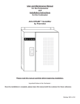
INSTRUCTION & OPERATIONS MANUAL AQ COMFORT PORTABLE MULTIFUNCTIONAL INDOOR AIR QUALITY MONITOR E Instruments International LLC 402 Middletown Blvd, Suite 216 Langhorne, PA, USA 19047 Phone (215) 750-1212 Fax (215) 750-1399 [email protected] www.E-Inst.com AQ COMFORT Instruction & Operations Manual Version 1.01 TABLE OF CONTENTS CHAPTER 1 .................................................................................................................... 3 TECHNICAL SPECIFICATIONS & SAFETY GUIDELINES ........................................... 3 CHAPTER 2 .................................................................................................................... 7 INTRODUCTION ............................................................................................................. 7 CHAPTER 3 .................................................................................................................... 9 BASIC INSTRUMENT OPERATION .............................................................................. 9 CHAPTER 4 .................................................................................................................. 12 POWER REQUIREMENTS ........................................................................................... 12 CHAPTER 5 .................................................................................................................. 13 SENSORS -TECHNICAL .............................................................................................. 13 CHAPTER 6 .................................................................................................................. 16 AQ COMFORT SETUP ................................................................................................. 16 CHAPTER 7 .................................................................................................................. 19 INTERNAL DATA STORAGE ...................................................................................... 19 CHAPTER 8 .................................................................................................................. 21 WIRELESS REMOTE PRINTER................................................................................... 21 CHAPTER 9 .................................................................................................................. 23 ZERO & SPAN CALIBRATION .................................................................................... 23 CHAPTER 10 ................................................................................................................ 30 AQ GAS SOFTWARETM ............................................................................................... 30 CHAPTER 11 ................................................................................................................ 36 MAINTENANCE ............................................................................................................ 36 CHAPTER 12 ................................................................................................................ 38 AQ COMFORT OPTIONS ............................................................................................. 38 CHAPTER 13 ................................................................................................................ 41 BASIC TROUBLESHOOTING ...................................................................................... 41 CHAPTER 14 ................................................................................................................ 43 REPLACEMENT PARTS .............................................................................................. 43 Page 2 of 44 AQ COMFORT Instruction & Operations Manual Version 1.01 CHAPTER 1 TECHNICAL SPECIFICATIONS & SAFETY GUIDELINES AQ COMFORT - AIR QUALITY MONITOR 1. PHYSICAL: Material: Blue ABS plastic case Dimensions (monitor): 8.6 x 3.9 x 2 inches: 220 x 100 x 52 mm (H x W x D) Weight: (monitor): 1.6 lbs. / 0.725 kg Shipping Dimensions & Weight (monitor & all accessories): 8 lbs. / 3.6 kg 20” x 19” x 9” / 50.8 cm x 48.2 cm x 22.8 cm 2. POWER: 12 Volt, 8 AH rechargeable Li-Ion battery pack Operating time: 8 – 12 hours 110/240 VAC input, 12 V/2.5A fast charger Charging time: 3 hours maximum 3. DISPLAY: 2.6” x 1.4” 128 x 64 graphic, chip on glass (white backlit) LCD display. Rotating display depending on monitor case orientation Small and large fonts, plus inverted background color for help messages Battery condition & charger operation indicator 4. WIRELESS REMOTE PRINTER (Optional) 2” high resolution, high speed, graphic thermal printer, with charger, prints: A. current set of data B. stored data C. periodic data printouts D. calibration history and external messages 5. INTERNAL INSTRUMENT PUMP Continuous Air sample pump: high quality diaphragm pump with long life motor 6. MEMORY STORAGE 1000 Internal memory storage tags, each tag stores one complete set of data 7. COMMUNICATIONS Bluetooth wireless: Class 1 (100m) USB Cable 8. SOFTWARE AQ GAS™ Windows PC Software Page 3 of 44 AQ COMFORT Instruction & Operations Manual Version 1.01 SENSORS 1. AIR QUALITY SENSORS – ELECTROCHEMICAL SENSOR CARBON MONOXIDE (CO) Std Range RANGE RESOLUTION ACCURACY 0 - 200 ppm 0.1 ppm +/- 1 ppm of rdg, +/- 0.2 ppm *Note: All Accuracies indicated above are under Laboratory Conditions 2. AIR QUALITY SENSORS – NON-DISPERSIVE INFRARED (NDIR) SENSORS SENSOR CARBON DIOXIDE (CO2) Std Range RANGE RESOLUTION ACCURACY 0 – 5000 ppm 1 ppm 2% of Rdg. + 10 ppm 4. OTHER SENSORS SENSOR RANGE RESOLUTION ACCURACY Temperature Type K (T1) 0 – 2000 ºF (0 – 1100ºC) 0.1 ºF (0.1 ºC) +/- 0.5 ºC 0-100ºC +/- 5% >100ºC Ambient Temperature -40 – 257 ºF (-40 – 125 ºC) 0.1 ºF (0.1 ºC) +/- 0.4 ºC (0-60 C) Relative Humidity 0 -100 % 0.1% +/- 2% RH Pressure +/- 80 mbar 0.1 mbar +/- 2 mbar Air Velocity 0 – 300 ft/sec 1 ft/sec Page 4 of 44 AQ COMFORT Instruction & Operations Manual Version 1.01 MODEL AQ COMFORT – SAFETY GUIDELINES This section provides general rules which must be followed for product safety, avoiding personal injury, damage to equipment and preserving the manufacturer’s warranty. Please take care to carefully observe the following instructions. A. PRODUCT SAFETY INSTRUCTIONS: NOTE: Please take special care when performing Span Calibration of the monitor. You cannot revert back to the factory setting after any adjustments! NOTE: CO2 should ALWAYS be Calibrated or Zeroed with a Cylinder of ZERO AIR. Do Not Use Ambient Air for CO2 sensor calibration. Do not operate the instrument outside of the parameters specified in the technical specifications Do not use or store the instrument together with any solvents Do not block the two (2) exhaust ports in the back of the instrument Do not expose the monitor to extreme hot or cold temperatures outside of the stated range in this manual Do not abuse the charger cord. Do not use power cord for carrying, pulling. Keep cord away from heat, oil, sharp edges, or moving parts. Damaged or entangled cords can increase risk of electric shock Only use the supplied, appropriate AC Charger If the monitor enclosure is ever unscrewed and taken apart, avoid overtightening the screws that hold the two main enclosure pieces together. Do not store or operate in dusty, dirty areas Always use the monitor with care and use the instrument properly Do not use force when disconnecting and reconnecting the Black external Temp, RH and Pressure Sensor (see photo below) Do not use instrument in the rain or high moisture areas to prevent water droplets on the black external Temp, RH, and Pressure Sensor. Remember to have the monitor checked and calibrated at least once a year to ensure sensor accuracy and compliance with existing standards DO NOT LIFT OR HANDLE THE INSTRUMENT BY THE BLACK EXTERNAL TEMP, RH, PRESSURE SENSOR HOUSING! See photo below Page 5 of 44 AQ COMFORT Instruction & Operations Manual Version 1.01 B. ELECTROMAGNETIC COMPATIBLITY Complies with EN61326-1, Portable Equipment The E Instruments AQ COMFORT Indoor Air Quality Monitor is a battery operated Portable device designed to be used by a qualified engineer/technician to make measurements in buildings and residential facilities. For long-term testing, you may operate the unit connected to the supplied charger by carefully following the product safety instructions in Section A above. C. ESD Protection In extreme cases or abnormal applications, Electrostatic Discharge can potentially cause serious and immediate damage to the electronic circuits of the instrument. D. BATTERY DISPOSAL & RECYCLING Recycle all applicable material properly. Take faulty/depleted batteries to proper collection/recycling centers Dispose of batteries and the monitor according to statutory regulations. Do not dispose of with regular household items. After the monitor’s useful life, please return to your local authorized E Instruments’ distributor or send back to E Instruments directly. We will ensure that it is disposed of in an environmentally friendly manner Page 6 of 44 AQ COMFORT Instruction & Operations Manual Version 1.01 CHAPTER 2 INTRODUCTION A. UNPACKING THE INSTRUMENT & PARTS IDENTIFICATION E INSTRUMENTS AQ COMFORT kits (excluding AQ Comfort-1) include as standard equipment: • • • • • • IAQ Monitor Model AQ COMFORT with CO2, Temp, %RH, Dew point Temp, WBT, Differential Pressure and Differential Temperature Internal Continuous Sampling Pump Battery charger / AC adaptor for the monitor USB Thumb Drive includes: • Instruction Manual Internal Wireless Bluetooth Calibration Certificate C. PROPER SAFE USE 1. Follow all the instructions in the AQ Comfort manual. 2. Do not block the two (2) exhaust ports in the back of the instrument housing. 3. Do not expose the monitor to extreme temperatures outside the stated range 4. Do not store or operate in dusty, dirty areas 5. Do not use instruments in the rain or high moisture areas to prevent water droplets on the external Temperature and RH Sensor. Page 7 of 44 AQ COMFORT Instruction & Operations Manual Version 1.01 LIST OF ABBREVIATIONS PARAMETERS CO2 CO Ta RH DPt WBT VEL ∆P T1 BAT NA Carbon Dioxide – NDIR measurement Carbon Monoxide Ambient (room) Air Temperature Percentage of Relative Humidity Dew Point Temperature Wet Bulb Temperature Air / Gas Velocity (measurement with optional pitot tube) Differential Pressure (with Velocity Probe turned OFF) Thermocouple Type K Temperature (T1 Input) Battery Life / Voltage Parameter Not Available UNITS PPM °F °C "WC mmHg "Hg PSI mmWC kPa mbar FPS MPS CMM CFM V Parts (of pollutant) per million Temperature Measurement in Fahrenheit Temperature Measurement in Celsius Inches of water (pressure measurement) Millimeters of Mercury (pressure measurement) Inches of Mercury (pressure measurement) Pounds per Square Inch (pressure measurement) Millimeters of water (pressure measurement) KiloPascals (pressure measurement) Millibars (pressure measurement) Feet per second (gas / air velocity measurement) Meters per second (gas / air velocity measurement) Cubic meters per minute (gas / air velocity measurement) Cubic feet per minute (gas / air velocity measurement) Voltage (battery) Page 8 of 44 AQ COMFORT Instruction & Operations Manual Version 1.01 CHAPTER 3 BASIC INSTRUMENT OPERATION The AQ COMFORT is operated by the 9 button keyboard located on the front of the monitor. The POWER key turns the instrument on and off. The MEASURE key shows the currently measured parameters. Displays the monitor’s currently measured data in either of two (2) fonts: A. Small fonts (all data displayed simultaneously plus range indicated, battery condition and time) B. Large fonts (four data parameters displayed simultaneously) Note: The AQ Comfort allows the user to ZOOM in and out of the screen by changing from Small to Large Fonts using the MEASURE again to zoom back out. key. Press Measure key Four (4) keys will bring up separate Menus: SETUP, CALIB, STORE, & PRINT. SETUP Controls all customization parameters, such as measurement units, for the monitor CALIB Controls calibration settings and zeroing of the monitor’s sensors. STORE Controls operation of the monitor’s internal data storage PRINT Executes print commands for the monitor’s optional remote Bluetooth printer The menus are navigated with the UP, DOWN, LEFT, RIGHT, & OK keys. Page 9 of 44 AQ COMFORT Instruction & Operations Manual Version 1.01 INSTRUMENT OPERATION OVERVIEW AQ COMFORT STARTING INSTRUCTIONS 1. Turn the AQ Comfort on by pressing the POWER key. The instrument’s internal pump will immediately turn on and the E INSTRUMENTS logo will appear. The instrument will begin to draw in air from the center SAMPLE IN inlet “A” at the bottom of the unit. 2. If applicable, attach the optional probe and sampling line to the monitor. 3. Press the MEASURE key to view the Main Measuring Screen including ambient temperature, barometric pressure, relative humidity and dew point. The toxic gas readings you selected in your kit are also displayed: CO2 & CO (CO will appear only if sensor was installed). 4. At initial startup, allow the CO2 sensor up to 1 minute to warm up and stabilize. CO2: 920PPM CO: 0PPM Ta: 79.1°F RH: 46.9% DPt:57.0°F ∆P: The MEASURE key allows the user to toggle/zoom between a small font and a large font screen. 0.0mb _____________________ Sampling 12:45:00 NOTE: Depending on the options enabled for your AQ COMFORT some of the entries in one or more of the displays shown above will be blank if that option is not available. The battery icon is displayed in the middle of the bottom line of the display. Its condition is marked by the shaded fraction of the icon. If the unit is powered by the battery charger a small “plug” icon will replace the battery icon. NOTE: When connecting the battery charger to the monitor make sure that the “plug” icon appears on the MEASURE screen. This ensures a proper power connection and charging of the batteries. Battery Full Battery Empty Battery Charger Connected 5. If you are using the monitor for the first time, press the SETUP key to set the appropriate parameters (i.e.: measurement units) for your application. See Chapter 5 for an explanation of each parameter. APR 1 ‘14 12:45:00 Temperature Units: F Measure Units: PPM Pressure Units: inWC Pumps: AUTO 750cc/m Velocity Probe: OFF Velocity Units: FPS Duct Size: 0 in2 Display Contrast: 24 Baudrate: 115 kbps Version: 1.02Li Page 10 of 44 AQ COMFORT Instruction & Operations Manual Version 1.01 6. All sensor readings shown on the screen indicate ambient measurements. To ZERO the gas sensors, please see Calibration Chapter 9 of this manual. 7. To obtain a printout of the data displayed, press the PRINT key. The cursor (reverse color) will point to: Print Test Record Press the OK key to execute a printout on the AQ Comfort’s optional Bluetooth remote printer. 8. Measured data can be stored in the monitor’s internal memory. Please refer to Chapter 7 for more details about data storage. Page 11 of 44 AQ COMFORT Instruction & Operations Manual Version 1.01 CHAPTER 4 POWER REQUIREMENTS The E Instruments AQ COMFORT Indoor Air Quality Monitor is a battery operated Portable device designed to be operated by a qualified engineer/technician to make measurements in buildings and residential facilities. For long-term testing please carefully follow the product safety instructions in Chapter 1. Power is supplied by a Li-Ion rechargeable battery pack. The battery pack will supply power to the monitor for about at least 8 hours of continuous operation. A 110 – 240 Volt AC charger having a 12 Volt DC / 2.5A output is supplied with the instrument. The battery charger will fully charge the battery pack in three hours. You can check the condition of the batteries at any time: 1. By pressing the MEASURE key, (small font screen) and observing the battery icon, located at the bottom of the display. Battery Full Battery Empty Battery Charger Connected 2. By pressing the MEASURE key, (large font screen), the user can scroll all the way to the end using the DOWN arrow key to observe the battery life shown in Voltage. When the unit is operating on its internal batteries, the voltage displayed will vary from an initial 8.0 to 8.4 volts (fully charged) dropping slowly to approximately 7 volts (batteries nearly empty). When the battery voltage drops to 7.1 volts a “low battery” warning will appear on the display. Within a few minutes later the instrument will automatically turn off, to preserve the remaining battery power for the sensor bias voltages. Page 12 of 44 AQ COMFORT Instruction & Operations Manual Version 1.01 CHAPTER 5 SENSORS -TECHNICAL The AQ Comfort Air Quality monitor’s sensors are grouped into three categories based on their principle of operation: 1. Up to one (1) CO (Carbon Monoxide) electrochemical gas sensor 2. One (1) NDIR (infrared gas sensors) – CO2 3. Non-gas sensors (Temperature, Humidity, Pressure, and Velocity) sensors The main section of the monitor houses all the electrochemical and NDIR gas sensors, battery pack, and PC board. On the bottom of the unit, there is a black external sampling system for Ambient Temperature and Relative Humidity. The figure below shows the internal manifold of the gas sensors inside the unit: SENSOR LIST: CO2 CO Page 13 of 44 AQ COMFORT Instruction & Operations Manual Version 1.01 1. ELECTROCHEMICAL SENSORS All electrochemical sensors are mounted on fitted socket fittings for easy installation and removal. The electrochemical sensor is described here: Carbon Monoxide sensor (CO) This is also a three electrode sensor that responds to carbon monoxide. It is equipped with an inboard filter to remove any interference from other acidic gases. 2. NDIR (INFRARED) SENSOR (CO2) A non-dispersive infrared (or NDIR) sensor is a simple spectroscopic device most commonly used to measure CO2 in indoor air quality applications. The main components are an infrared source (lamp), a sample chamber or light tube, a wavelength sample chamber, and the CO2 gas concentration is measured electrooptically by its absorption of a specific wavelength in the infrared (IR). The AQ Comfort Air Quality Monitor is equipped with one standard NDIR infrared sensor capable of CO2 measurement (standard range: 0 – 5000 ppm). Page 14 of 44 AQ COMFORT Instruction & Operations Manual Version 1.01 The NDIR sensor have the following specifications: GAS RANGE ACCURACY CARBON DIOXIDE (CO2) 0 – 5000 ppm 2% of reading + 10 ppm 3. NON-GAS SENSORS A. Ambient Temperature sensor This is a solid state sensor located on the front panel of the monitor. The ambient temperature is displayed on the MEASURE screen in either °F or °C. The dew point is calculated from the ambient temperature and relative humidity. The dew point is displayed on the Small and Large Font MEASURE screens as DPt. B. Humidity sensor This is a solid state sensor located on the front panel of the monitor. The relative humidity is displayed on the MEASURE screen in %RH (% Relative Humidity). The Wet Bulb is calculated from the ambient temperature, relative humidity, and barometric pressure. The wet bulb is displayed on the Large Font MEASURE screen only as WBT. C. External temperature sensor (T1) The thermocouple is located at the bottom right side of the monitor. It can be used with any optional or separate Type K thermocouple probe and/or wire. The T1 temperature measurements are displayed on the Large Font MEASURE screen only as T1. D. Differential Pressure / Air Velocity sensor. If the monitor comes with the Differential Pressure option and/or the air velocity option (optional separate L-type Pitot tube and pressure tubing), the internal pressure sensor is a very low range pressure sensor. The Velocity measurements are displayed on the MEASURE screen only as VEL. Differential Pressure is displayed on the MEASURE screen only as ∆P. E. Connecting Differential Pressure Hoses: Connect Metal Hose Connections to either P+ or P- Connection as shown. P+ only will give you Positive pressure; P- only will give you Negative Page 15 of 44 AQ COMFORT Instruction & Operations Manual Version 1.01 pressure. Plug in both as shown below for Differential Pressure. All single & differential readings are shown on main MEASURE screen as ∆P. SINGLE PRESSURE DIFFERENTIAL PRESSURE CHAPTER 6 AQ COMFORT SETUP The SETUP MENU allows the operator to change the instrument’s parameters. Page 16 of 44 AQ COMFORT Instruction & Operations Manual Version 1.01 APR 1 ‘14 12:45:00 Temperature Units: F Measure Units: PPM Pressure Units: mbar Pumps: AUTO 750cc/m Velocity Probe: OFF Velocity Units: FPS 2 Duct Size: 0 in Display Contrast: 24 Baudrate: 115 kbps Version: 1.02Li Every parameter listed on the SETUP MENU screen can be changed as follows: a. Use the UP / DOWN you wish to change. keys to move the highlighted line to the parameter b. Press OK to edit the value. The parameter you have chosen will become highlighted on the right side of the screen. This indicates that you are in edit mode. c. Use the UP / DOWN keys until the desired value of the selected parameter appears on the display. d. Press the OK key to execute the change. A more detailed explanation of each parameter follows: 1) DATE & TIME: The monitor’s internal clock is displayed in the format month-dayyear, hour-minute-second. Hours are always displayed using a 24-hour clock format. 2) TEMPERATURE UNITS: The UP / DOWN keys toggle between °F (Fahrenheit) and °C (Celsius). The T1 temperature reading and ambient temperature will be displayed, printed, and saved in the selected units. 3) PRESSURE UNITS: Pressure measurements can be shown in millibar (mbar), inches of water (inWC), millimeters of water (mmWC), millimeters of mercury (mmHG), inches of mercury (inHG), pounds per square inch (psi) or kilopascal (kPa). 1 mbar = 0.10 kPa = 0.40 inWC = 10.2 mmWC = 12.95 inHg = 0.75 mmHg = 1.45 PSI Page 17 of 44 AQ COMFORT Instruction & Operations Manual Version 1.01 4) VELOCITY UNITS: (Velocity Option) Select between feet per second (FPS), meters per second (MPS), cubic feet per minute (CFM), or cubic meter per minute (CMM). AIR VELOCITY AND DIFFERENTIAL PRESSURE CAN NOT BE MEASURED SIMULTANEOUSLY. USER MUST CHOOSE ONE OR THE OTHER. To change the selection, hit the SETUP key. Using the DOWN arrow key, scroll Down to VELOCITY PROBE and hit OK. The OFF/ON selection will be highlighted. Use the Up & Down arrow keys to change the selection from OFF to ON or vice versa. With the Velocity Probe Selection OFF, the AQ Comfort will measure Differential Pressure (∆P) automatically. With the Velocity Probe Selection ON, the AQ Comfort will measure Air Velocity (VEL) automatically. When you have your selection chosen, hit the OK button and the entire Velocity Probe will be highlighted again. Hit the MEASURE Button to get back to the Main Measurement screen once you are complete. 5) DUCT SIZE: (Velocity Option). Estimate the cross-section area of your Ducts in square inches (in2) and set this value to obtain automatic & accurate Air Flow measurements in CFM or CMM. NOTE: When using the Velocity Feature on the AQ Comfort it is recommended to ZERO the readings BEFORE using the Pitot tube to ensure proper Velocity measurements. See Chapter 9 for instructions on Zeroing the AQ Comfort. (Zero Gas Sensors) Connecting Pitot Tube: In air conditioning, heating and ventilating work, it is helpful to understand the techniques used to determine air velocity. In this field, air velocity (distance traveled per unit of time) is usually expressed in feet per minute (FPM). By multiplying air velocity by the cross section area of a duct, you can determine the air volume flowing past a point in the duct per unit of time. Volume flow is usually measured in cubic feet per minute (CFM). To make Air Velocity measurements using the AQ Comfort, you will need to use the Optional 12” Pitot tube. Follow Steps #5 & #6 above to (1) turn the Velocity Probe option ON (VEL will appear on the unit’s main screen) and (2) set up your Duct Size. Connect the supplied hoses from the Pitot tube to the (-) and/or (+) PRESSURE connections on the bottom of the AQ Comfort. 6) PUMP: Pump status is displayed: a) AUTO - Automatic sample mode is selected b) OFF – The internal Pump is turned off. 7) DISPLAY CONTRAST: Select the best value for viewing the LCD screen. 8) BAUDRATE: The communication speed for both the USB port and the Bluetooth connection is set here. The default setting is 115 kbps. Page 18 of 44 AQ COMFORT Instruction & Operations Manual Version 1.01 CHAPTER 7 INTERNAL DATA STORAGE The STORE MENU allows the operator to store data and manage the internal storage tags. Store Current Buffer Select Buffer Start Average Test Start Periodic Store Select Interval: 1m Review Buffer Name Buffers Erase Buffers 00: TAG#00 The AQ Comfort has 1000 internal storage tags/memory spots. Each tag stores one complete set of air quality data. There are two ways to store air quality data to the monitor’s buffer. You can either store data by selecting the option STORE CURRENT DATA after pressing the STORE key, or alternatively you can make use of the monitor’s capability of storing data automatically on a periodic basis. You can set the time period between data storage. The STORAGE MENU shows the relevant display lines for the storage options. 1. STORE CURRENT BUFFER: The monitor will store one set of data into the tag currently selected. The index number and the name of this tag appear at the bottom of the screen. 2. SELECT BUFFER: Selecting this item will display an index of the monitor’s 1000 internal storage tags. Tags that are used have an icon next to their index number. The selected storage tag is indicated by the reverse color line. When data is stored, this pointer will automatically advance to the next available tag. If you want to store data in a different location, use the UP, DOWN, & OK keys to select a new tag. As you scroll up and down, tags containing data show their date and time at the bottom of the display. Empty tags show the word empty. 3. START AVERAGE TEST: This will begin a period of data averaging, with the average values stored periodically in successive memory tags. The interval between each storage cycle is displayed below and can be set by the user. Once enabled, this line will read: STOP AVERAGE TEST. Page 19 of 44 AQ COMFORT Instruction & Operations Manual Version 1.01 4. START PERIODIC: This will turn on the periodic store function. In this mode, the unit will continuously store data at an interval displayed on the next line. Once enabled, this line will read: STOP PERIODIC. 5. SELECT INTERVAL: The time between each store is set here. This can range from 10 seconds to 60 minutes. 6. REVIEW BUFFER: This choice allows you to view previously saved data. Press OK. The display will switch to the data screen, with the data in the first tag displayed. The time and date when the data was saved will appear at the bottom of the display. Use the UP / DOWN keys to scroll through the tags. 7. NAME BUFFERS: This choice will take you to *** NAME BUFFERS *** another screen where you can rename one or Starting Tag: 00 more tags. This is useful if you use several tags Ending Tag: 00 together to form a test series. Select the starting Name:xxxxxxxxxxxxxxxx test index with the UP / DOWN / LEFT / RIGHT 1 2 3 4 5 6 7 8 9 0 ◄ keys and press OK. Next, select the ending test A B C D E F G H sym ► index. The cursor will move to the first character I J K L M N O P shift of the first tag’s name, and the alphanumeric Q R S T U V W X Y Z keyboard will appear. Use the UP / DOWN / LEFT / RIGHT keys to navigate around the keyboard, and press OK to select the letter or number. For lower-case letters, highlight shift and press OK, for symbols, highlight sym and press OK. The arrows in the corner will move the cursor forward or backward through the tag’s name. 8. ERASE BUFFER: This option is used to erase stored data. Data that has been stored in the monitor’s memory will be retained even after the instrument has been shut off and its batteries removed. To erase the contents of a specific tag, use the UP / DOWN keys to move the arrow to the desired tag. As you scroll up and down, tags containing data show their date and time at the bottom of the display. Empty tags show the word empty. If you wish to erase all 1000 of the monitor’s stored data, move the arrow to the entry ALL TAGS and press OK. Page 20 of 44 AQ COMFORT Instruction & Operations Manual Version 1.01 CHAPTER 8 WIRELESS REMOTE PRINTER The AQ Comfort uses an optional wireless Bluetooth remote printer. The printer is powered by a rechargeable battery. An AC charger is supplied with the printer. First you must turn the printer on. Then press PRINT to scan and connect with your wireless printer to establish communications between the monitor and the printer. * WIRELESS PRINTERS * Scan for printers Press OK to search * WIRELESS PRINTERS * Device Found Press OK to Connect Device 1:001122334455 * WIRELESS PRINTERS * Device Connected Press OK to Continue Device 1:001122334455 When you have connected successfully the printer’s green status light will turn on. Pressing the PRINT key will now display the PRINT MENU. The PRINT MENU allows the user to print test records. Print Test Record Start Test Log Log Interval: 60s Print Buffer Configure Record Edit Customer Name Calibration Record Paper Feed On/Off Mobile Printer... PRINT TEST RECORD: This option will print a test record of the current air quality parameters. Serial #: 000000 Company Name TEST RECORD AUG 1 ‘14 12:45:00 CO2: CO: T ambient: RH: DPt: WBT: BP: VOC: XX.X XXXX XXX XX.X XXX XXXX XXXX XXX % PPM ºF % ºF ºF psi PPM PRINT TEST LOG: This option begins a log of the following air quality parameters: CO2, Temperature, %RH, Wet Bulb, Dew Point, and Carbon Monoxide. Page 21 of 44 AQ COMFORT Instruction & Operations Manual Version 1.01 LOG INTERVAL: This selects the interval between each log entry. The interval can be set between 1 and 60 seconds. PRINT BUFFER: This option is used to print data stored in the monitor’s memory. Each line corresponds to one storage tag. Tags containing data show an icon next to the index number. When you scroll up and down, the date (mm/dd) and time (hh/mm) when the data was stored appear at the bottom; empty tags show the word “empty”. To print the contents of a specific tag, use the UP / DOWN keys to move the arrow to the desired tag and press OK. If you wish to print the entire monitor’s stored data in sequence, move the arrow to the entry ALL TAGS and press OK. CONFIGURE RECORD: This option allows the user to add, delete, or change the order of the parameters that appear on the paper print out. EDIT CUSTOMER NAME: This will display a screen where you can change the information printed at the top of each printout. Usually the customer’s name or the operator’s name appears here. To edit this information, use the UP / DOWN / LEFT / RIGHT keys to navigate around the keyboard, and press OK to select the letter or number. For lower-case letters, highlight shift and press OK, for symbols, highlight sym and press OK. The arrows in the corner will move the cursor forward or backward through the name. ** EDIT HEADER INFO * EINSTRUMENT AQ COMFORT 1 A I Q 2 B J R 3 C K S 4 D L T 5 E M U 6 F N V 7 G O W 8 H P X 9 0 ◄ sym ► shift Y Z CALIBRATION RECORD: This option will print a record of each sensor’s last calibration, including the date of calibration and span gas value used. PAPER FEED: This toggles the printer’s motor on and off, advancing the paper out the top of the printer as needed. The motor will not turn on if there is no paper present. MOBILE PRINTER: The WIRELESS PRINTERS screen will appear. You can disconnect your current Bluetooth connection and connect to another printer in range. Page 22 of 44 AQ COMFORT Instruction & Operations Manual Version 1.01 CHAPTER 9 ZERO & SPAN CALIBRATION NOTE: CO2 should ALWAYS be Span Calibrated or Zeroed with a Cylinder of ZERO AIR. Do Not Use Ambient Air for CO2 sensor calibration. Every instrument must occasionally be tested against some known value or standard in order to make sure that its accuracy has not deteriorated. If the instrument is reading outside of the stated accuracies in this manual, the unit should be calibrated by following the procedures described in this chapter. This chapter will contain all of the information on calibrating and adjusting the AQ Comfort IAQ Monitor. The term Span Calibration means comparing the AQ Comfort’s readings to a standard concentration (i.e.: calibrated gas bottles) and adjusting/changing the AQ Comfort’s individual sensor’s readings to match the standard concentration for the most accurate measurements. The term ZERO calibration refers to the user’s ability to calibrate each sensor with zero concentration of the targeted gas. See Chapter 11, Maintenance, for recommended frequencies of each procedure. If the unit is returned to E Instruments for Span Calibration, the unit will be shipped back after Calibration with a new Calibration Certificate valid for one (1) year. If the unit is Span Calibrated in the field, the original calibration certificate is no longer valid. NOTE: Please take special care when performing Calibration of the monitor. You cannot revert back to the factory setting after any adjustments! **** CALIBRATION **** Zero Gas Sensors Zero CO2 Sensor Zero Thermocouples Zero Errors Zero Time: 60sec Span Time: 120sec ** Span Lockout ** Sensor History Span CO: xxxx PPM Span CO2: xxxx PPM Span Velocity: xx " Span ∆P: xx " Span AmbT: xx.x C Span RH: xx.x % Cal Thermcple :xxxF The CALIBRATION MENU lets you set span calibration values for each sensor and performs all sensor calibrations. The CALIBRATION MENU is shown below. A brief explanation of the parameters shown follows below: ZERO GAS SENSORS: This will set the zero point of CO, Pressure & Velocity values. ZERO CO2 SENSOR: This will set the zero point of CO2. ZERO THERMOCOUPLE: This calibrates the external thermocouple input (T1) to ambient temperature. ZERO ERRORS: This will display a list of sensors that were out of the monitor’s acceptable range during the last zero countdown. Page 23 of 44 AQ COMFORT Instruction & Operations Manual Version 1.01 ZERO TIME: This is the countdown time for the zero procedure. The zero cycle time should set at 20-60 seconds. SPAN TIME: When carrying out a span calibration, you must introduce the span gas for an appropriate amount of time before the monitor executes the span calibration. This setting, which is the same for all sensors, controls this time interval. The span time is indicated in seconds. SPAN LOCKOUT: This controls access to the remaining span calibration menu options. Span lockout prevents accidental or mistaken calibrations. Span lockout is enabled and disabled by entering a 4-digit code. See section D below for the code. SENSOR HISTORY: The date that each sensor was installed is displayed, along with the date the sensor was last calibrated and the span gas concentration used. SPAN XXXX: The remaining lines of the CALIBRATION MENU are used for carrying out span calibrations of the CO and CO2 sensors. For detailed use of these settings, please refer below. A. ZEROING THE AQ COMFORT Select CALIB key to go into Calibration Mode There are two (2) methods to Field-Calibrate the GAS & CO2 Sensors on the AQ Comfort. 1. ZERO Gas Sensors using the ZERO AIR Cylinder (to zero all gas sensors) 2. Using Outside fresh Air to Calibrate the gas sensors (except the CO2 sensor) 1. ZEROing ALL GAS Sensors using a certified Cylinder of ZERO AIR If you have a gas cylinder/bottle of ZERO AIR you can use this for Zeroing ALL of the gas sensors in the AQ Comfort. If you do not have this cylinder, please contact E Instruments to purchase our optional Calibration Kit consisting of ZERO AIR & regulator for proper calibration of the AQ Comfort (part #: AQCAL). ZERO GAS SENSORS: This will set the zero point of the CO value. Connect Cylinder to the “A” inlet connection on the bottom of the AQ Comfort using the optional accessories included in the CALIBATION KIT (Part #: AQCAL). See CALIBRATION APPARATUS section below for how to connect. Have the cursor (reverse color) point to the line: Zero Gas Sensors Page 24 of 44 AQ COMFORT Instruction & Operations Manual Version 1.01 Press the OK key to execute a zero cycle of all the gas sensors. This procedure should last 60 seconds. At the end of the zero period, the AQ Comfort reads the output of all gas sensors and sets them all to zero. If no error messages appear at the end of the countdown, proceed with your measurements. ZERO CO2: This will set the zero point of CO2. You must use cylinder of ZERO AIR for CO2 ZERO CALIBRATION. Connect Cylinder to the “A” inlet connection on the bottom of the AQ Comfort using the optional accessories included in the CALIBATION KIT (Part #: AQCAL). See CALIBRATION APPARATUS section below for how to connect. Scroll down using down arrow key and have the cursor (reverse color) point to the line Zero CO2 Sensors Press the OK key to execute a zero cycle of the CO2 Sensor. This procedure should last 60 seconds. If no error messages appear at the end of the countdown, proceed with your measurements. 2. ZEROing Sensors using OUTDOOR FRESH AIR (with the exception of CO2) If you are not using bottled ZERO AIR, it is important to select a location where the ambient environment of the monitor is clean from traces of carbon monoxide or other toxic gases. The user should be at least 20-30 feet (6-10 meters) away from any buildings, parking lots, highways, and any other possible exhaust sources. If in doubt of the ambient air, please use the ZERO AIR cylinder. When you turn the instrument on in clean ambient air, wait at least one (1) minute to allow the monitor to warm up before carrying out the zero calibration. ZERO GAS SENSORS: This will set the zero point of CO, Pressure and Velocity values based on the clean ambient conditions. Have the cursor (reverse color) point to the line: Zero Gas Sensors Press the OK key to execute a zero cycle of all the gas sensors. This procedure should last 60 seconds. Page 25 of 44 AQ COMFORT Instruction & Operations Manual Version 1.01 At the end of the zero period, the AQ Comfort reads the output of all gas sensors and sets them all to zero. If no error messages appear at the end of the countdown, proceed with your measurements. ZERO THERMOCOUPLE: This calibrates the one external thermocouple input (T1) to ambient temperature. Be sure the Thermocouples being testing are at room temperature before Calibrating To start the zero procedure, press the CALIB key and select ZERO Thermocouples. B. SPAN CALIBRATION E Instruments recommends performing a span calibration of the instrument once every 6 months for maximum accuracy, or at a minimum of once per year. The parameters that require a span calibration are carbon monoxide and carbon dioxide. You can carry out all span calibrations in sequence. NOTE: You must always span calibrate the instrument when a sensor is replaced. Span calibration using your own gas If you wish to use your own span gas to perform span calibrations you must take certain precautions and follow the instructions below carefully in order to calibrate the sensors properly. Notice that you will need a number of certified gas cylinders. Make sure that you use a bypass flow meter as shown below in the CALIBRATION APPARATUS section, in order to supply an adequate flow of span gas without developing excessive or insufficient pressure on the sensors. Make sure the concentration of the calibration gas is within the range of each sensor. Do not use gas that will over-range the sensor. The CO span gas can be in the range of 30 - 200 PPM, 2% accuracy with balanced nitrogen, preferably. . The CO2 span gas can be in the range of 2500 PPM, 2% accuracy, with balance air Make sure the concentration of the calibration gas is within the range of each sensor. Do not use gas that could over-range the sensor. Page 26 of 44 AQ COMFORT Instruction & Operations Manual Version 1.01 For greatest accuracy, it is recommended that you use a span gas value close to the gas concentration you expect to measure. C. CALIBRATION APPARATUS During calibration an adequate flow of span gas must be supplied without developing excessive pressure on the sensors. A compressed cylinder of span gas must be equipped with a primary pressure regulator. Connect the regulator of the bottled gas to the AQ Comfort “A” inlet in the center port on the bottom of the unit. A simple way to feed the span gas to your monitor is by an open T-connection that will ensure that gas is fed at ambient pressure. The regulator valve is used to control the flow of gas to the monitor. To ensure that the span gas is fed properly and as efficiently as possible, connect a bypass flow-meter at the outlet. Adjust the regulator to maintain approximately 750 cc/min of flow at the outlet. You must not feed gas to the AQ COMFORT under pressure and you must not starve the AQ COMFORT's pump for gas. When feeding the gas, you must maintain a reasonably constant pressure, near ambient pressure. Page 27 of 44 AQ COMFORT Instruction & Operations Manual Version 1.01 ZERO AIR Gas Bottle Calibration: T – for proper air/press ure flow Gas Hose from Cylinder connects to Center “A” Inlet on Bottom of AQ Comfort for Span Calibration D. CALIBRATION PROCEDURE The following page illustrates the sequence of key strokes to carry out a span calibration of the AQ Comfort. It is assumed that the instrument has been zeroed and there have been no error messages. Electrochemical Gas Sensors 1. Turn the AQ Comfort on and press Measure. Allow the instrument to warm up for 15 minutes before beginning the calibration procedure. 2. Connect the outlet from the tee fitting of the gas calibration fixture to the “A” inlet connector on the bottom of the monitor using the set up shown in the above calibration apparatus photo: NOTE: Please take special care when performing Calibration of the monitor. You cannot revert back to the factory setting after making any adjustments! 3. Turn on the gas flow and observe the gas readings on the instrument. If the gas reading for the sensor being calibrated does not increase after a few seconds, turn off the gas flow until the problem is found. Otherwise, press OK. 4. Press the key labeled “CALIB” to enter the calibration menu. 5. Scroll down to SPAN TIME and set the value to 20 seconds. Page 28 of 44 AQ COMFORT Instruction & Operations Manual Version 1.01 6. Scroll down to the sensor to be calibrated first. If the calibration lock is on, enter the password 1315. 7. Use the arrow keys to enter the span value printed on the calibration cylinder being used. Press OK. 8. When the countdown reaches 3 seconds, there will be a series of beeps indicating that the calibration has been preformed. 9. Verify that the reading for the sensor being calibrated matches the value entered in the calibration menu, and that the reading for all of the other sensors is zero. 10. Turn off the gas flow. 11. Repeat this procedure for each electrochemical sensor to be calibrated. Temperature and Humidity Please contact E Instruments for proper Calibration Procedure Pressure and Air Velocity Calibration Procedure 1. 2. 3. 4. 5. 6. 7. Connect a pressure calibration standard to the pressure (+) connector on the bottom of the instrument. In the SETUP menu, make sure the velocity sensor is off. Press the “CALIB” key to enter the calibration menu. Scroll down to SPAN ∆P and press OK. Using the calibration standard, generate a pressure value near the maximum stated value for the scale being used, for instance 80 mbar if using the mbar range. Enter the value generated as the span value using the arrow keys, and press the enter key. Verify that the reading on the instrument matches the reading on the calibration standard. Page 29 of 44 AQ COMFORT Instruction & Operations Manual Version 1.01 CHAPTER 10 AQ GAS SOFTWARETM 1. COMMUNICATIONS The AQ Comfort Monitor communicates with a PC either using the USB cable or wirelessly using its internal Bluetooth (BT) module. If your computer does not have internal BT capabilities, use the external BT module that is supplied with the AQ Comfort The communication protocol is as follows: BAUD RATE: 115000 baud FORMAT: 8 bits, 1 stop bit, no parity HANDSHAKE: None USB CONNECTION For USB connections, use the A-to-B type USB cable supplied with the instrument. To establish a USB connection, the FTDI USB driver must first be installed on your computer. The USB drivers for Windows computers are located on the E INSTRUMENTS USB Thumb Drive: When you plug the USB cable from the computer to the monitor, you should hear a small “da-ding” sound indicating that the USB connection has been made. If you have the FTDI USB driver already installed in your computer the computer will know and will NOT initialize the “New Hardware Wizard”. If the New Hardware Wizard appears you need to install the FTDI USB driver. To install this driver: 1. Locate the FTDI USB driver on the CD or download it from the E INSTRUMENTS website and save it to your desktop. 2. The downloaded file is zipped. Double-click the zipped folder and choose Extract All Files. Extract the files to a folder on the Desktop. The driver files are in the FTDI_USB folder. 3. Follow the instructions in the New Hardware Wizard 4. You will have to go through the wizard twice, once to install the ftdiport.inf file and once for the ftdibus.inf file. BLUETOOTH CONNECTION For Bluetooth connections, the connection process varies with different Bluetooth devices. Follow your manufacturer’s instructions for adding a device. The E INSTRUMENTS’ Bluetooth modem is a Class 1 device, with a maximum range of 100m. Obstacles such as walls and equipment will reduce the effective range. Page 30 of 44 AQ COMFORT Instruction & Operations Manual Version 1.01 The AQ Comfort is supplied with a Bluetooth Dongle to make connections to PC’s without internal Bluetooth capabilities. 1. 2. 3. 4. 5. 6. Insert Bluetooth Dongle on an open USB drive on your PC. Next, insert Dongle’s CD ROM. If it does not open automatically, go to “My Computer” and open the software program from the CD ROM. Follow the on-screen instructions to install software. After restarting your PC wait for the Add New Connection Wizard to appear. If it does not appear, then double click on the Bluetooth symbol at the bottom of the screen. Power on your AQ COMFORT. Select “Express Mode” and click next. Your instrument will appear as “AQ COMFORT-xxxxx”. (The “xxxxx” will be the serial number of the AQ Comfort.) You may have to click on “refresh”. Select your AQ COMFORT, and then click next. Page 31 of 44 AQ COMFORT Instruction & Operations Manual 7. 8. Version 1.01 You will automatically be connected to your AQ COMFORT. If a passkey is required it is “0000” (four zeroes). The next prompt will give you the COM Port number, please make note of this as you will need it to communicate with the AQ GAS software. Then click “Next”. 9. The Bluetooth Settings window will now appear with your AQ COMFORT listed with serial number shown. Double click on the icon to connect. Once successfully connected, your icon should change from the one below on the left to the one below on the right. 10. Run the AQ GAS software and add the Bluetooth COM Port number to begin communicating with your AQ COMFORT. Page 32 of 44 AQ COMFORT Instruction & Operations Manual Version 1.01 ALL CONNECTIONS When you connect your AQ COMFORT to your computer for the first time, the connection will be assigned a unique comport number. Remember the comport number as it will be needed to open an AQ GAS session. You can find the comport associated with your E INSTRUMENTS in the Windows Device Manager. To open the Device Manager: Go to the Windows “START” menu, click “RUN” and type devmgmt.msc (Or go to the Control Panel, choose the System icon, then the Hardware tab, and click the Device Manager Key). A window will open that will list “PORTS” among other items. Click on “PORTS”. The comport will be listed as: o USB Serial Port (USB) o Standard Serial over Bluetooth link (Bluetooth) 2. USING AQ GAS SOFTWARE You can enhance the performance and versatility of the E INSTRUMENTS AQ COMFORT by using the AQ GAS software program. AQ GAS is available for most Windows operating systems. The AQ GAS software is a robust package that allows you to: 1. Monitor all Air Quality parameters. 2. Record maximum, minimum, average for all Air Quality parameters. 3. Select a variety of saving and printing options. 4. Retrieve stored data. Page 33 of 44 AQ COMFORT Instruction & Operations Manual Version 1.01 5. Set alarms for every air quality parameter including recording the time duration that alarms have been exceeded. 6. Plot bar graphs and time plots of all air quality parameters. The AQ GAS software can be downloaded from the included USB Thumb Drive. Windows 8 users may have to load drivers from the following link: http://www.makeuseof.com/tag/how-can-i-install-hardware-with-unsigneddrivers-in-windows-8/ Consult the AQ GAS manual for details on installing and operating the program. The manual can be accessed by clicking on “Help” and then “How Do I…” in the AQ GAS software program. STARTING AQ GAS 1 2 3 Before starting AQ GAS, have your AQ COMFORT turned on and connected via USB or Bluetooth. Start the AQ GAS Software program. If you have connected before, the monitor icon will automatically appear. If this is the first time you are connecting, you will need to add a new port. On the AQ GAS window click on “Connections”, then click on “Add Port”. Page 34 of 44 AQ COMFORT Instruction & Operations Manual 4 5 6 Version 1.01 Enter the COM port number which appeared in the Device Manager, and click “OK”. The COM port with its number should appear on the left side of the AQ GAS window. AQ GAS will look for a monitor on this port. After a moment the E INSTRUMENTS monitor icon should appear. You are now connected to your monitor. Click on the E INSTRUMENTS icon. A menu will appear. Choose “Monitor” from the menu. (Follow the AQ GAS manual for further instructions). Page 35 of 44 AQ COMFORT Instruction & Operations Manual Version 1.01 CHAPTER 11 MAINTENANCE The AQ Comfort Indoor Air Quality Monitor is a sophisticated analytical instrument designed to perform accurate air quality measurements. However, because the monitor is a portable, field/lab used instrument that can be used in many environments, care must be taken to prevent physical and environmental abuse to help maintain troublefree operation. There are some components that will require periodic inspection and/or replacement. INTERVAL ITEM PROCEDURE Weekly ZERO Check of ALL Gas Sensors Perform using ZERO AIR Weekly ZERO Check of the CO2 Sensor Perform using ZERO AIR Annually SPAN Calibration of ALL Gas Sensors Perform Span or Send to Factory *Note: These stated intervals are dependent on the unit’s usage and applications A. Sensor Replacement This should be an infrequent operation, since the sensors have a typical life of a few years. If you receive an error message for one of the sensors during instrument operation you may have to replace the sensor. Please contact E Instruments for replacement sensors. The user can send the unit back to the factory for sensor installation and recalibration of the instrument or the sensors can be replaced in the field. The replacement sensors will be supplied with installation instructions. NOTE: You must always span calibrate the instrument every time you replace a sensor. NOTE: CO2 should ALWAYS be Calibrated or Zeroed with a Cylinder of ZERO AIR. Do Not Use Ambient Air for CO2 sensor calibration. Page 36 of 44 AQ COMFORT Instruction & Operations Manual Version 1.01 B. Printer Paper Replacement The external printer uses a high quality 2" thermal paper. Keep any spare paper rolls in a cool dark place to prevent paper discoloration. 1) Press the open key on the printer to open the paper cover 2) Insert the paper as shown in the image. Remove any remaining core of a used paper roll. 3) Make sure to align the paper roll properly. 4) Pull the paper out as shown in the image, and close the cover. 5) Tear off any excess paper in the direction of the side of the printer. Page 37 of 44 AQ COMFORT Instruction & Operations Manual Version 1.01 CHAPTER 12 AQ COMFORT OPTIONS The E INSTRUMENTS’ AQ COMFORT is an extremely versatile Indoor Air Quality (IAQ) measurement system that meets many Air Quality measurement requirements. It has been designed as a modular system, permitting the installation of most of the various available options. This manual describes the complete instrument equipped with all the options. The AQ Comfort’s standard capabilities include (1) NDIR CO2 sensor (0-5,000 ppm), Ambient Temperature, Relative Humidity, Wet Bulb, Dew Point, one (1) separate Type K (TcK) thermocouple temperature measurement input, Air Velocity measurements, differential pressure measurements, 1000 internal storage tags, Bluetooth wireless PC communications, REAL-TIME Data Logging capabilities using the Optional AQ GAS WindowsTM software, USB Cable, and extensive user-friendly help screens. The available additional gas sensor options and accessories are: 1. AIR QUALITY MONITOR SENSORS* Carbon Monoxide (CO) – electrochemical sensor (0-200 ppm) 2. OPTIONAL VINYL CARRYING CASE Vinyl Carrying Case which protects the AQ Comfort and any accessories from damage during transportation. Extra inserts for other instruments and accessories. 3. OPTIONAL MAGNETIC RUBBER BOOT The Rubber Protective Boot protects the AQ Comfort while allows for Hands Free Operation using the built-in magnets. Page 38 of 44 AQ COMFORT Instruction & Operations Manual 4. Version 1.01 OPTIONAL EXTERNAL MEASURING PROBE Certain applications might have the need for the optional probe (12” long stainless steel probe with 10’ ft long hose) for hard to reach places, separate areas, etc. The probe consists of the stainless steel extraction probe, the sampling line and a Type K thermocouple for external temperature measurements with the probe. This standard probe (Part # AACSF22) is suitable for temperatures up to 800ºC/1470ºF. The end of the probe’s sampling line connects to the “A” inlet connector on the bottom of the AQ Comfort and the thermocouple connector connects to the TcK TEMPERATURE 1 input on the bottom of the AQ Comfort. 5. OPTIONAL L-SHAPED PITOT TUBE Pitot tube – This optional L-shaped pitot tube consists of stainless steel tubing with the tips open and bent at a certain angle to properly measure air and/or gas velocities. The Pitot tube must always be oriented with the open tips parallel to the direction of the air flow. The end of the Pitot tube assembly is connected by means of two flexible hoses to a very accurate pressure transducer located inside the monitor. 6. OPTIONAL DIFFERENTRIAL PRESSURE HOSES (part #: AACKP01) This optional PRESSURE HOSES consist of two (2) clear hoses for either (1) single positive pressure connection, one (1) single negative pressure connection, or (2) hoses for differential pressure using both connections simultaneously. The hoses connect to the (-) and/or (+) PRESSURE connections on the Bottom of the AQ Comfort. Page 39 of 44 AQ COMFORT Instruction & Operations Manual 7. Version 1.01 OPTIONAL WIRELESS REMOTE PRINTER (Part #: E852110) The AQ Comfort uses a wireless Bluetooth remote printer. The printer is powered by a rechargeable battery. An AC charger is supplied with the printer. The printer is optional with the AQ Comfort. See Chapter 7 for more information 8. OPTIONAL CALIBRATION KIT (ZERO AIR) (Part #: AQ CAL) The AQ Comfort uses a bottled Cylinder of ZERO AIR for ZERO Calibration. Part #: AQCAL comes with (1) 17L ZERO AIR Cylinder & (1) Regulator Part #: AQAIR is replacement (1) 17L ZERO AIR Cylinder only Page 40 of 44 AQ COMFORT Instruction & Operations Manual Version 1.01 CHAPTER 13 BASIC TROUBLESHOOTING ZERO ERRORS Channel Possible Causes Resolution (Electrochemical sensors) CO Sensor has been recently exposed to gas and has not yet returned to zero. Purge for 10 minutes with fresh air, monitor sensor voltage, and re-zero. Insufficient Warm Up Allow the sensors to warm up after 10 minutes Incorrect ZERO calibration Repeat ZERO cal in fresh air or with ZERO AIR cylinder Pump Failed Check pump flow, if pump failed replace Battery was dead, sensor has destabilized. Charge battery, wait up to 24 hours for sensors to stabilize, and re-zero. Sensor cell life has expired. Call E INSTRUMENTS replacement. Temperature Thermocouple Thermocouple is not connected Check electrical connections running to the probe Infrared CO2 No response from infrared Zero period must be at least system 45 seconds. Zero the instrument again with a cylinder ZERO AIR. Infrared system is reporting error code Infrared system may need maintenance. Velocity Velocity probe/Pitot Tube is not connected Check probe and connections. Bluetooth connection failure Connection Failed Redo connection process Page 41 of 44 AQ COMFORT Instruction & Operations Manual Version 1.01 TROUBLESHOOTING Symptoms Monitor will not turn on. (Screen is off) Monitor turns on but screen is blue or faded. Possible Causes Resolution Battery is discharged. Plug in the charger. Monitor should turn on. Battery is not charging. Check the charger and jack. Check the case for excessive heat. Internal initialization problem. Reset the monitor. Internal initialization problem. Reset the monitor. Monitor is overheating. Unplug charger. Turn on & off to reinitialize. Page 42 of 44 AQ COMFORT Instruction & Operations Manual Version 1.01 CHAPTER 14 REPLACEMENT PARTS PART NUMBER DESCRIPTION AQ CO2-5000 NDIR CO2 Sensor (0-5000 ppm) AQ CO-200 CO Sensor (0-200 ppm) YAACSM03A Protective Magnetic Rubber Boot AQ Gas AQ Gas PC Software Kit with USB E852130 Bluetooth Dongle AQ CO2-5000 NDIR CO2 Sensor (0-5000 ppm) E852010 Rechargeable Battery Pack E85-9078 Printer Paper Roll E852020 AC Charger, 100-240VAC/50-60Hz with 12V Output E852130 Bluetooth Adapter/Dongle AQCAL Calibration KIT – ZERO AIR Cylinder w/ Regulator AQAIR Replacement ZERO AIR Cylinder ONLY PRO8140 Vinyl Carrying Case with Shoulder Strap E852110 Remote Bluetooth Wireless Printer w/ AC Charger AACSF22 12” Probe and 10’ hose AACKP01 Differential Pressure Hoses Page 43 of 44 AQ COMFORT Instruction & Operations Manual Version 1.01 E Instruments International LLC 402 Middletown Blvd, Suite 216 Langhorne, PA, USA 19047 Phone (215) 750-1212 Fax (215) 750-1399 [email protected] www.E-Inst.com Page 44 of 44