1
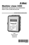
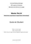
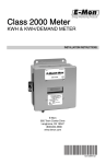
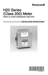
Class 500 Meter
ADVANCED KWH/DEMAND METER
INSTALLATION INSTRUCTIONS
62-0399-02
CLASS 500 METER
TABLE OF CONTENTS
Section 1.0
Introduction
3
Section 2.0
Internal Electronic Assemblies
4
Section 2.1
Main Power Board
5
Section 2.2
Display Board
6
Section 2.3
Input Board
7
Section 3.0
Meter Technical Specifications
8
Section 4.0
Safety Label Definitions and Information
11
Section 5.0
Precautionary/Safety Information
12
Section 6.0
Meter Installation
13
Section 6.1
Mounting the Class 500 Meter
13
Section 6.2
Main Power Board Connections
14
Section 6.3
Phasing of Line Voltage
16
Section 6.4
Current Sensor Installation & Wiring
17
Section 6.5
Main Power & Current Sensor Wiring Diagram
20
Section 6.6
Line Voltage/Current Sensor Diagnostics
21
Section 6.7
RS-485 Wiring
23
Section 6.8
RS-232 Communications
25
Section 6.9
Modem Wiring
27
Section 6.10
Modbus RTU Wiring
31
Section 6.11
BACnet Wiring
31
Section 6.12
Connecting Class 500 Meters to USB Key using RS485
32
Section 6.13
Ethernet Communications
33
Section 7.0
Multiple-Load Monitoring
34
Section 8.0
Preventative/Scheduled Maintenance
35
Section 9.0
Lithium Battery Replacement
36
Section 10.0
Class 500 Meter Operating Modes
38
Section 10.1
Start Up Screens
38
Section 10.2
Normal Mode Display Screens
39
Section 10.3
How to Program the Display Screens
43
Section 11.0
Frequently Asked Questions
46
Section 12.0
Protocol Descriptions
48
Section 13.0
High Voltage Metering
58
Section 14.0
Meter Limited Warranty
61
62-0399-02
2
CLASS 500 METER
1.0 INTRODUCTION
The Honeywell Class 500 meter is a 3-phase meter with communications. The device
is used to monitor electric power usage of individual loads after the utility meter and
store kW and kVAR data for automatic meter reading. The Class 500 meter is dual
protocol capable and provides both RS485 and Ethernet communications. Installation
must only be performed by qualified personnel and in accordance with these
instructions and all applicable local and national electrical codes. Honeywell and its
representatives assume no responsibility for damages or injury resulting from the
improper installation of this meter.
Verify the input voltage rating and configuration on the unit panel label to ensure that it
is suitable for the intended electrical service. For example, Class 500 meters labeled
for 120/208V service MUST NOT be installed on service feeds of 277/480 volts or 347/
600 and vice versa.
Meter Labeled:
Works On:
120V
120V, Single Phase
120/240V
120/240V, Single Phase
277V
277V, Single Phase
208V
208V, Three Phase
240V
240V, Three Phase
400V (380, 415)
400V, Three Phase
480V
480V, Three Phase
600V
600V, Three Phase
Verify that the Class 500 meter’s current sensors are sized suitably for the load to be
monitored. Compare the color of the arrows on the current sensors to the chart below
to confirm the correct current sensor is being used.
Sensor Arrow Color Code
Sensor Rating
Brown
100 A
Red
200 A
Yellow
400 A
Black
800 A
Blue
1600 A
White/Black
3200 A
3
62-0399-02
CLASS 500 METER
CAUTION
Internal circuit card components are extremely sensitive to electrostatic
discharge. Prior to handling or touching internal circuitry, discharge any static
buildup on your person. To discharge yourself, touch a grounded metal object
such as conduit or an earth grounded metal enclosure.
WARNING
Use of this instrument, Class 500, in a manner inconsistent with this manual or
not specified by the manufacturer in writing, can cause permanent damage to
the unit and/or serious injury to the operator. The protection and safety
features provided by this equipment may become impaired or otherwise
compromised.
NOTE: If any trouble arises during installation or functional verification operations, do
not immediately remove unit. Before removing the unit, contact Honeywell’s
technical support department. Honeywell’s technical department will assist
you in detailed troubleshooting of the Class 500 installation.
2.0 INTERNAL ELECTRONIC ASSEMBLIES
The unit is comprised of two major subassembly boards, the main power board and
the display board. Both circuit boards are mounted inside a NEMA 4X rain tight
enclosure.
MAIN POWER
BOARD
DISPLAY
BOARD
M33270
Fig. 1. Internal Electronic Assemblies.
62-0399-02
4
CLASS 500 METER
2.1 Main Power Board
Connections to this board include the MAIN Power Input and current sensors. The
MAIN Power Input terminals are positions one through four on the four position screw
terminal block, TB1. These terminals are covered with a protective shield for safety
purposes. The current sensor assemblies interface to the TB2, TB3 and TB4. Each
terminal block corresponds to an input voltage phase; care must be exercised to
ensure that each current sensor is connected to the correct terminal block. One three
terminal screw connector(TB42) is provided for RS-485 communications. One RJ-45
jack (J8) is provided for 10/100-base T Ethernet.
The contact is a solid-state switch for the phase-loss alarm function. Switching is
limited to 100 ma (0.1 amp) and voltage should not exceed 60 Volts AC or DC.
The (N.O.) contact closes within the meter due to the loss any one of the three lines of
voltage inputs to the meter. The contact closure may be used to activate an audible
alarm, light, control coil, or other indicator device. This alerts appropriate personnel to
the loss of voltage. An emergency phone dialer may also be programmed to send
notification automatically by phone, text, or pager. Alarming devices to be supplied by
others and are not included by with the Honeywell Class 500 meter.
One two terminal screw connector provides phase loss alarming.
Optional card header J4 is a 10 positions for use with modem and LonWorks TP/FT-10.
J3
J4
TB1
POSITIONS 1-4
MAIN POWER INPUT
ETHERNET
CONNECTION
TB1 POSITIONS 6-10
CURRENT SENSOR
INPUTS
RS-485
CONNECTION
PHASE OUTPUT
M33271
Fig. 2. Main Power Board.
5
62-0399-02
CLASS 500 METER
2.2 Display Board
The display board connects to the main power board via a flex ribbon cable and the
board mounts on the inside of the housing door.
No additional connections to the display board are required. The display board’s LCD
readout indicates the metered values as well as errors associated with the Class 500
meter, such as phase loss or sensor error conditions.
DOWN
UP
SELECT
Fig. 3. Display Board.
62-0399-02
6
MENU
M33279
CLASS 500 METER
2.3 Input Board
The Class 500 meter is supplied with an input board which allows it to accept pulses
(dry contact) from third party meters, such as gas, water, BTU, etc.
+
INP1
+
INP2
+
OUT1
+
OUT2
INPUT TERMINALS
CL5000 METER INPUT BOARD
M33272
Fig. 4. Input Board.
7
62-0399-02
CLASS 500 METER
Amperage
Enclosure
Communication
Protocol
Current
Sensor/Option
50-
208
100-
J
03
KIT
Current
Sensor/Option
Voltage
H
Current
Sensor/Option
Class
Example
Brand
3.0 METER TECHNICAL SPECIFICATIONS
H50-208100-J03KIT
Brand
Honeywell
Class
500
Voltage
120, 208, 400 (380-415), 480, 600
Amperage
2HV, 100, 200, 400, 800, 1600, 3200
Enclosure
J (JIC Steel), I (Interior only), R (Rain tight)
Communication
Protocol
01 (EZ-7, EZ-7 ETHERNET),
02 (MODBUS RTU, EZ-7 ETHERNET),
03 (BACNET MSTP, EZ-7 ETHERNET),
04 (EZ-7, MODBUS TCP/IP),
05 (EZ-7, BACNET IP),
06 (MODBUS RTU, MODBUS TCP/IP),
07 (LONWORKS TP,EZ-7 ETHERNET),
08 (LONWORKS TP, MODBUS TCP/IP),
09 (EX-7, EZ-7 ETHERNET WITH MODEM),
10 (EZ-7, MODBUS TCP/IP WITH MODEM),
11 (EZ-7, BACNET IP WITH MODEM)
Current Sensors/
Options
KIT (Split Core), SCS (Solid-Core), -SP (Single or Two Phase
- 2 element)
Ordering Information: Define brand, class, input voltage, current sensor rating,
enclosure, protocols/options, and sensor type in the format A-BB-CCC-DDDD-E-FF-GHHH, where:
A = Brand: H for Honeywell
BB = designates Class: 320 (32) or 500 (50) meter
CCC = input voltage: (208, 480, 600, 120 volt for high voltage applications only)
DDDD = current sensor rating: (100, 200, 400, 800, 1600, 3200, 25HV)
E = enclosure: J = metal (type 1), R = non-metallic (type 4X)
FF= protocol option:
G = no package = “blank”
“-S= Single or Two Phase (Optional)
HHH= Sensor Type: kit=split-core, scs= solid-core, non-supplied blank”
62-0399-02
8
CLASS 500 METER
3.0 METER TECHNICAL SPECIFICATIONS (CONTINUED)
Input Voltage
Configuration
Single Phase 3-wire (Delta) or 4-wire (Wye)
Mains Voltage Input
Up To 480 VAC RMS Available
Input Power
6 VA Maximum Rating
Current Sensor
Rating
Up To 3200 Amps RMS AC Available
Power Factor
0.5 Leading or Lagging
Line Frequency
50-60 Hz
Metering Accuracy
ANSI C12.20
Voltage Operating
Range
+/-10% of Rated Load
Temperature Range
-20 C To +50 C (Standard indoor enclosure):
Temperature Range
-20 C To +70 CNEMA 4X (NEMA 4X outdoor enclosure)
Relative Humidity
Range
0-95% Non-condensing
Altitude
2000 Meters Maximum
Voltage Overload
+25% Continuously: +100% For 20 Cycles
Current Sensor
Overload
100% For 1 Minute Without Damaging Meter
Pollution Degree
Degree 2 In Accordance With IEC 664
Installation
(Overvoltage)
Category
Category 111
Measurement
Category
Category 111
Enclosure Material
Indoor Housing Rating JIC Steel (Standard): NEMA 12
Outdoor Housing Rating Rain Tight
Display Readout
4- Line LCD
Standards
EN 61326-1:2006 IEC 61010-1:2001, 2nd Edition
Standard Ranges
2-Wire Delta 120 VAC: 100, 200, 400, 800,1600, 3200 Amp
4-Wire Wye 120/208 VAC: 100, 200, 400, 800,1600, 3200 Amp
3-Wire Delta 120/240VAC:100, 200, 400, 800,1600, 3200 Amp
4-Wire Wye 277/480 VAC: 100, 200, 400, 800,1600, 3200 Amp
2-Wire Wye 277 VAC: 100, 200, 400, 800,1600, 3200 Amp
4-Wire Wye 400 VAC: 100, 200, 400, 800,1600, 3200 Amp
3-Wire Delta 480 VAC: 100, 200, 400, 800,1600, 3200 Amp
4-Wire Wye 600 VAC: 100, 200, 400, 800,1600, 3200 Amp
9
62-0399-02
CLASS 500 METER
Modem Interface
IDR Interface Port
Cable:
UL-listed Telephone Cord,
6-cond. 300 VAC, Stranded
Cond. 22-26 AWG.
Cable Connector:
RJ-45 male IDC
Input/Output Voltage:
+5 VDC/18 VAC
Ckt Input Isolation
5.3K VAC for 1 Minute
Baud Rate:
9600
Cable:
UL-listed/rated Telephone
Cord. 4-cond.
Input/output Voltage:
Ground-isolated +/-5.4VDC
Cable Connector:
RF-45 Male IDC Or Screw
Terminal Termination
Circuit Input Isolation:
5.3kVAC
Circuit output Isolation:
21.5kVAC
Isolated Pulse/Alarm Outputs
(TB5, TB6):
Output Voltage Potential:
Recommended
In-line Fuse
Battery Cell
62-0399-02
0 VDC to +5 VDC Logic Levels
Mating Plug Connector:
Weidmuller PN: 152876
Signal Isolation Voltage:
5.3K VAC for 1 Minute
Manufacturer:
Littlefuse
Mfg. Part No:
KLDR.100
Rating:
100mA, Time-delay, 600VAC
Cartridge Fuse
Description:
Non-rechargeable Cell Used
For Memory Retention
Manufacturer:
Panasonic
Mfg Part No:
CR2032
Working Voltage:
3 VDC
Current Capacity
225 mAHr
Electrolyte:
Manganese Dioxide Lithium
10
CLASS 500 METER
4.0 SAFETY LABEL DEFINITIONS AND
INFORMATION
The 500 meter may contain one or more of the following labels. Operator(s) should
familiarize themselves with the meaning of each label to minimize risk.
FCC Notice
This equipment has been tested and found to comply with the limits for a Class B
digital device, pursuant to part 15 of the FCC Rules. These limits are designed to
provide reasonable protection against harmful interference in a residential installation.
This equipment generates, uses and can radiate radio frequency energy and, if not
installed there is no guarantee that interference will not occur in a particular
installation. If this equipment does cause harmful interference to radio or television
reception, which can be determined by turning the equipment off and on, the user is
encouraged to try to correct the interference by one or more of the following measures:
- Reorient or relocate the receiving antenna.
- Increase the separation between the equipment and receiver
- Connect the equipment into an outlet on a circuit different from that to which the
receiver is connected.
- Consult the dealer or an experienced radio/TV technician for help.
Standards Compliance:
BACnet MS/TP and IP protocol is BTL listed.
LonWorks TP/FT-10 protocol is LonMark® certified.
The presence of this label is a cautionary indicator identifying a
danger risk. The manual should be consulted prior to proceeding.
The presence of this label indicates an electrical shock hazard exists in
the location or area where the label is placed. Prior to proceeding, the
MAINS power must be disconnected and the manual consulted for
safety information.
11
62-0399-02
CLASS 500 METER
5.0 PRECAUTIONARY AND SAFETY
INFORMATION
CAUTION
Internal circuit card components are extremely sensitive to electrostatic
discharge. Be careful not to touch internal circuitry prior to discharging any
static buildup on your person. To discharge yourself, touch a grounded metal
object such as conduit or an earth-grounded metal enclosure.
WARNING
High voltages present on main PCB terminal block TB1 screw terminals. Risk
of serious injury and/or electrical shock exists. Prior to performing any wiring
operations, review all contents of the user manual and de-energize the MAINS
power switch. Only qualified personnel should perform installation wiring.
Installation wiring must comply with all local and national electrical codes.
WARNING
NEVER open front panel of unit while unit has MAINS power applied. Failure to
comply can increase the risk of serious injury and/or electrical shock.
62-0399-02
12
CLASS 500 METER
6.0 METER INSTALLATION
6.1 Mounting the Class 500 Meter
6-35/64 (166)
5/8 (16)
6-35/64
(166)
7-51/64
(198)
3-17/64 (83)
Ø 1-3/32 (28) THROUGH
NEAR SIDE ONLY
3-25/64
(86)
1-5/8
(41)
M34684
Fig. 5. Enclosure Dimensions
Use appropriately sized mounting hardware to fasten the meter enclosure to the
selected mounting surface.
The four housing mounting holes are centered 6.75” H x 4” W.
NOTE: Units housed in UL Type 1 JIC steel enclosures must only be installed in
indoor environments, where they will not be affected by the elements.
13
62-0399-02
CLASS 500 METER
6.2 Main Power Board Connections
1.
2.
Installing a temporary ground for ESD protection: With all circuits de-energized,
connect a temporary protective earth ground connection for ESD protection.
Prior to performing any unit wiring, be sure to discharge any static on your person.
Installing the Class 500 protective earth ground: Connect an earth ground wire
to the Class 500 protective earth ground lug with a torque of 7 N-m. * for meters
in metal enclosures.
WARNING
Failure to attach the protective earth ground wire securely to the meter creates
a potential shock hazard. Do not operate the meter without a protective earth
ground connection securely installed.
3.
Wire Entry: One 3/4” conduit opening is located on the bottom of the unit enclosure. This opening is used for bringing in MAINS power and for current sensor
wiring. Route the appropriate cabling to and through the respective enclosure
opening.
4.
After installing the conduit fitting and conduit, verify that each conduit slip nut is
securely tightened to its respective conduit fitting. Any unused openings must be
sealed with a UL rated plugging device suitable for the rating of the enclosure
(check formatting).
NOTE: Metallic enclosure has one additional 1/2” conduit opening at top of unit.
5.
Unit MAINS wiring: The first four positions of terminal block TB1, located at the
bottom left corner of the main power board, are clearly labeled Phase A, B, C, N
(neutral). Earth Ground MUST be connected to the PCB mounting screw in the
lower right corner.
a. Connect the NEUTRAL wire to the appropriate terminal block position.
Fig. 6. Terminal Block TB1.
NOTE: For 3-wire delta-type applications, do NOT connect the NEUTRAL wire.
Remove the terminal block screw for this position.
b. Earth Ground. Connect the Earth Ground to the PCB mounting screw in the
lower right corner.
62-0399-02
14
CLASS 500 METER
c. External Switch Mechanism/In-Line Fuse Installation.
To ensure a safe installation, the Class 500 meter requires an external switch
mechanism, such as a circuit breaker, be installed on the Class 500 MAINS
input wiring. The switch mechanism must be installed in close proximity to
the meter and easily reachable for the operator. This device must also be
marked as the disconnecting device for the Class 500 meter. Install 1/10
Amp Slow Activation in-line fuses with the suitable voltage rating for each
conductor phase at the MAINS input to the meter. The fuses must be labeled
to indicate voltage and current rating as well as element characteristics. The
fuse element must be slow activating type.
d. Connect the three AC main power wires (Phases A, B and C) to their respective positions as labeled on terminal block TB1 and tighten to 7 in-lb. After all
conductors are connected to each of their respective terminal block positions
and tightened down, verify that each terminal block screw is securely fastened by gently tugging on each conductor.
NOTE: On Single phase connections: Connect two AC main power wires to
phases A and B - Connect jumper from B to C - factory installed for Single
Phase option. Verify that no conductor wires are frayed or shorting to adjacent terminal block positions.
e. Turn ON the AC main power input. The meter display will light up and scroll
through 7 displays. Each display is visible for 5 seconds. Display screens are
as follows:
f.
Screen 1 - Total kilowatt-hours (kWh) consumed
Screen 2 - Peak demand (kW) with date & time stamp
Screen 3 - Actual load (kW) with preset date & time
Screen 4 - Average current (amps) per phase
Screen 5 - Average voltage (volts) per phase
Screen 6 - Average voltage (volts) phase to phase
Screen 7 - Power factor (PF) per phase
Verify the voltage readings on Screen 5 using an AC voltmeter. Typical readings shown below are measured phase to neutral for 4 wire and phase to
phase for 3 wire. Readings should be +/- 10% of nominal.
Meter Type
Nominal Voltage
Limits (+/- 10%)
120/208V, 3ø, 4 Wire
120/240V, 1ø, 3 Wire
120V, 1ø, 2 Wire
120 VAC (L-N)
108 to 132 VAC
277/480V, 3ø, 4 Wire
277V, 1ø, 2 Wire
277 VAC (L-N)
249 to 305 VAC
240V, 3ø, 3 Wire
240 VAC (L-L)
216 to 264 VAC
400V, 3ø, 4 Wire (380, 415) 230 VAC (L-N)
207 to 253 VAC
480V, 3ø, 3 Wire
480 VAC (L-L)
432 to 528 VAC
600V, 3ø, 4 Wire, (wye only)
347 VAC (L-N)
312 to 380 VAC
NOTE: Meters are powered by phases A and B. The displayed voltages will be the
measured AC voltage between phases.
15
62-0399-02
CLASS 500 METER
6.3 Phasing of Line Voltage
The 3-phase AC power input must be in proper phase sequence. Single phase option AC power input must be in proper phase sequence. If the sequence is incorrect or a
phase is missing, there will be a message on the meter’s display: “PH Sequence Error”
or “PH Missing:. (Refer to the section on Line Voltage Diagnostics if this message is
present.) When the line voltage is connected correctly, the meter’s display will be blank
(no message.)
Wait for the meter display to scroll to the voltage display. Verify that the meter reads
correct voltages on all three phases. Repeat Step 6.2.5.F.
Once the meter displays the correct line voltages and there are no error messages,
you are ready to connect the current sensors to the meter. Before continuing with the
installation, verify that the seven screens display as follows:
Screen 1 (kWh):
Should read 0.0 kWh; if not, should be reset.
Screen 2 (kW Peak Demand):
kW peak should read 0.0 kW. There will not be a
date/time stamp yet. If there is a kW peak recorded,
it should be reset later.
Screen 3 (Load/Clock Calendar): Should read 0.0 kW load.
Screen 4 (Amps per Phase):
There should be 0.0 on all three phases. Or
in the Single Phase option - 0.0 in A and B
phases.
Screen 5 (Volts RMS Phase to Neutral): See the section 6.2.5.F.
Screen 6 (Volts RMS Phase to Phase): See the section 6.2.5.F.
Screen 7 (Power Factor Per Phase):
There should be 0.0 PF on all three phases.
Or in the Single Phase option - 0.0 in A and B
phases.
NOTE: The meter will be reset later via the software during “startup” procedures.
62-0399-02
16
CLASS 500 METER
6.4 Current Sensor Installation & Wiring
Once the AC voltages have been confirmed to be within acceptable limits, you are
ready to install the current sensors. TB2 is the input for Phase A, TB3 is the input for
Phase B and TB4 is the Phase C input. For the Single Phase option: use TB1 pos 5&6
are for the A Phase - TB1 pos 7&8 are for the B phase -factory installed jumper wire on
positions 9&10. Factory installed Jumper should not be removed.
The Class 500 meter can only be used with two types of 0-2V current sensors:
1.
2.
Split-core current sensor. This sensor opens so that it can be attached around
the circuit being monitored without interrupting power. Unless otherwise specified, all Class 500 meters are supplied with this sensor type.
Solid-core current sensor. This sensor does not open and requires the monitored
conductor to be removed from the circuit to install the current sensor. This type is
only supplied when specified at time of order.
6.4.1 Installing the Split-Core Current Sensor Assembly
1.
Each phase being monitored will require one two-piece current sensor assembly.
Open the two-piece current sensor assembly by releasing the nylon clamp using
a fl at head screwdriver.
Fig. 7. Split Core Current Sensor.
2.
Reassemble the current sensor assembly around the conductor(s) to be monitored. Ensure the current sensor halves marked “Load” are both facing the load
side of the conductor. The colored arrow will be on the source side of the conductor being monitored and MUST be pointed in a clockwise direction around
the conductor being monitored. Tighten the nylon clamp to complete the assembly.
17
62-0399-02
CLASS 500 METER
LOAD
SOURCE
M33213
Fig. 8. Installation of a Split Core Sensor.
IMPORTANT:
When looking from the source side of the conductor(s) being monitored, you
should see the arrow on the current sensor assembly. The arrow should be
pointing in a clockwise direction around the conductor(s) being monitored. If
the arrow is not positioned on the source side, inaccurate readings will result.
6.4.2 Current Sensor Wiring
Once the current sensors are installed onto their appropriate phase conductors, you
can begin terminating the current sensors onto the Class 500 main board. The current
sensors can be extended up to 500 feet for remote monitoring applications. To extend
the length of the wires, use #22 AWG twisted-pair wire with one white and one black
wire.
The easiest way to connect the current sensors is to use the meter’s built-in current
sensor diagnostics. To do this, there must be at least 1% of the meter’s current rating
(amps) fl owing in each of the conductors being monitored. The Class 500 meter’s
diagnostic program will provide data to ensure that the current sensor installation is
done properly.
The current sensor connection points are located at the bottom right of the main power
board. These are terminals 5 through 10 of terminal block TB1. Each sensor connects
to two terminals, one labeled “Black” and the other “White.” Current sensors should be
connected to the meter one at a time and verified using the current sensor diagnostic
program.
Connect one of the current sensors to TB1 terminals 5 and 6 (Phase A). Wait 5
seconds and look at the meter display.
62-0399-02
18
CLASS 500 METER
6.4.2 Current Sensor Wiring (continued)
If the meter displays an error message (see below), remove the wires from terminals 5
and 6 and install them on terminals 7 and 8 (Phase B). if an error message occurs with
the sensor attached to terminals 7 and 8, try again on terminals 9 and 10 (Phase C).
The “CT Error: * “message will disappear when the current sensor is connected to the
correct terminals (phase).
Error Messages: CT ERROR: A
CT ERROR: A B
CT ERROR: A C
NOTE: The 1-Phase option will only display errors for A and B.
Refer to the section on Current Sensor Diagnostics for assistance in troubleshooting
these errors.
6.4.3 Main Power
After the meter circuit wiring has been examined for correctness, power may be
applied to the circuit board. There are three LEDs located in the upper right corner of
the Meter Board labeled BEAT, STATUS and LOAD. The BEAT and STATUS LEDs will
blink once per second when the meter is operating normally, twice per second if there
is a problem. If the monitored circuit is under load the LOAD LED will actively blink. A
heavy load will cause the LED to blink faster than a light load. Very light loads will
result in an extended blink time.
19
62-0399-02
CLASS 500 METER
6.5 Main Power & Current Sensor Wiring Diagram
TERMINAL BLOCK LOCATED INSIDE E-MON D-MON® METER
LINE VOLTAGE
ØA ØB ØC
N
2
1
1
1
CURRENT SENSORS
ØA
ØB
ØC
W
B W
B
W B
3
A
3
B
3
LOAD
C
N
SOURCE
1
RECOMMENDED FUSES OR CIRCUIT BREAKER PER THE NATIONAL
ELECTRICAL CODE (METER LOAD 6VA.)
2
NEUTRAL NOT USED IN DELTA SYSTEM.
3
SPLIT-CORE CURRENT SENSORS. INSTALL ACCORDING TO
INSTRUCTIONS.
M34291
Fig. 9. 3-Phase - 3-Wire or 3-Phase - 4-Wire Installation Diagram.
TERMINAL BLOCK LOCATED INSIDE METER
LINE VOLTAGE
ØA ØB ØC N
1
1
CURRENT SENSORS
ØC
ØB
ØA
W B W B W B
3
3
2
A
2
LOAD
SOURCE
B
N
1
RECOMMENDED FUSES OR CIRCUIT BREAKER PER THE NATIONAL
ELECTRICAL CODE (METER LOAD 6VA.)
2
CURRENT SENSORS INSTALLED ACCORDING TO INSTRUCTIONS.
3
INSTALL JUMPER WIRES.
M34842
Fig. 10. Single-Phase, 3-Wire Volt Installation Diagram
62-0399-02
20
CLASS 500 METER
6.6 Line Voltage/Current Sensor Diagnostics
Following is a list of diagnostic messages that may appear on the meter display.
DIAGNOSTIC MESSAGES SHOULD NOT BE ON CONTINUOUSLY WHEN THE
METER IS INSTALLED PROPERLY AND IS IN WORKING ORDER.
6.6.1 Line Voltage Diagnostics
The diagnostics program detects line voltage faults by displaying one of two
messages:
PH Missing: B C or Phase sequence error.
PH Missing: B C: Indicates that the line voltage is missing on Phase B and/or Phase C.
This message will appear whenever the power on either Phase B or Phase C is off.
Screen 5 (Voltage per Phase) will also indicate a loss of line voltage.
Phase sequence error : Indicates that the single phase or the three phase line voltage
is not hooked up in the proper phase sequence. This message should never be seen
continuously on the display during normal operation. The meter will not display correct
electrical data in this condition. The phase sequence problem must be remedied in
order for the meter to work properly.
21
62-0399-02
CLASS 500 METER
6.6.2 Current Sensor Diagnostics
The load current must be at least 1% of the meter’s rated load in order to use the
diagnostic function. Current sensor diagnostics can detect:
1.
2.
3.
Reversed current sensors
Incorrect phase correspondence
Unusually low power factor (0.642 or lower)
CT Error: (ABC) is used to detect the swapping of current sensor phases. This
message could (in some rare cases) indicate a low (<65%) power factor condition. This
message may appear intermittently due to changes in line conditions. It should not be
on continuously.
NOTE: If you have connected the current sensor to all three terminals and the error
message is still appearing, reverse the black and white wires and repeat the
previous steps until the correct connection is found.
If the CT Error: message disappears, you have found the correct sensor connection;
however, the current sensor was not installed properly around the conductor, or the
sensor wires were extended and not spliced together correctly. Correct the sensor
installation, reconnect the black wire to the black terminal and the white wire to the
white terminal on the plug and reinstall the plug into the correct phase terminal for that
current sensor. The error message should disappear and the current sensor is now
installed properly.
If the CT Error: message does not disappear at any time while trying all 3 inputs both
ways, check the AC voltage input from the current sensor between the black and white
wires using an AC voltmeter. It will read approximately zero volts indicating that the
load current is very small (or zero) or the current sensors are not secured properly
(tight connection between core halves or lead splices not secure.)
Once the first current sensor is connected properly and the error message disappears,
repeat the previous procedure for the remaining two current sensors. When all error
messages have disappeared and all sensors are installed correctly, the meter is
operational.
62-0399-02
22
CLASS 500 METER
6.7 RS-485 Wiring
Communication will be over both RS485 and Ethernet for increased flexibility with
various BAS equipment. Class 500 dual protocol capable with choices of EZ7,
Modbus, BACnet, and LON talk. The BAS meter will be fully capable of interfacing with
a BAS and an AMR (Automated Meter Reading) system simultaneously and
independently
RS-485 communication allows a computer or modem to communicate with one or
more Class 500 meters. You can connect as many as 52 meters along a 4000-foot RS485 cable run. Class 500 Smart meters are available with your choice of RS485 communication options: Modbus, BACnet, and E-Mon Energy (EZ7).
There are four communication protocols available through the Class 500 RS-485
connection. They are EZ7, Modbus RTU, BACnet MS/TP, and Lonworks FT-10. The
protocol is chosen when ordering the Class 500 meter. A second protocol is available
through the Ethernet port. The Ethernet protocol is also chosen when the meter is
ordered. See ordering information for the available choices.
Daisy-Chain Method
This is the simplest method for connecting meters together.
M32776
Fig. 11. Daisy-Chain Configuration.
1.
2.
Connect the +(high) terminal of PORT 1 of each meter together so that the + terminals on all meters are linked, + to + to +...
Connect the -(low) terminal of PORT 1 of each meter together so that the - terminals on all meters are linked, - to -...
23
62-0399-02
CLASS 500 METER
3.
Connect the GND terminals of PORT 1 of each meter so that the GND terminals
on all meters are linked, GND to GND to GND.
RS-485
TERMINAL
M33274
Fig. 12. RS-485 Terminal
After performing these steps, all of the meters will be connected in a daisy chain
configuration. This network of meters can then be connected to the RS-485 network
and communication can be established.
Internal Modem
An optional internal modem inside one meter will communicate with the others via the
RS-485 network. Simply connect one of the two telephone jacks on the modem to the
telephone line to complete the installation.
Local Computer
A local computer installed in the building can communicate with the RS-485 network.
The computer must be connected to an RS-232 key. The RS-232 key is then
connected to an available RS-485 jack in the meter using an RJ-11 cable.
NOTE: Don’t confuse the modem’s telephone jacks with the RS-485 jacks!!!
NOTE: When using one meter with an external modem, only the telephone line is
connected. RS-485 is not needed.
62-0399-02
24
CLASS 500 METER
6.8 RS-232 Communications
6.8.1 Hardwired System using the RS-232 Communication Key
The RS-232 communications key allows you to connect Class 500 meters to a
personal computer that has the Honeywell Energy™ software installed. The computer
communicates with the meters through the RS-232 key.
The RS-232 key must be located within 15 feet of the host computer.
UP TO 4000
FEET TOTAL
PC
CHANNEL 1
~
~
UP TO 52
CLASS 5000
METERS
RS-232 SERIAL
PORT COM1
OR COM2
15 FEET MAX RS-232
KEY*
AC ADAPTER
CHANNEL 3
CHANNEL 2
UP TO 4000
FEET TOTAL
UP TO 52
CLASS 5000
METERS
~
~
M33275
Fig. 13. RS-232 Configuration.
6.8.2 Connecting the RS-232 Key to the Computer
The RS-232 key is supplied with:
a. (1) 8-conductor cable fitted with RJ-45 plugs
b. (1) DB-9 serial COM port adapter
c. (1) AC adapter that converts 120VAC to 9VDC for powering the RS-232 key
Connection Steps:
1.
2.
3.
Connect the 8-conductor cable to the left-side jack (labeled “RS232”) on the rear
panel of the RS-232 key.
Connect the appropriate COM port adapter (DB-9) to the serial port on the back
of the computer. Plug the 8-conductor cable from the RS-232 key into the COM
port adapter.
Connect the provided AC adapter into the rear panel input on the RS- 232 key.
Plug the adapter into a 120VAC outlet. On the front panel of the RS-232 key, two
LEDs (POWER ON and AC ON) will light up.
25
62-0399-02
CLASS 500 METER
NOTE: When the Honeywell Energy™ software is accessed on the computer, a third
LED (RS232 READY) will turn on. This indicator will light up as soon as the
Honeywell Energy software is booted up and the correct COM port is set up
via the settings provided in the software’s Locations menu.
6.8.3 Connecting Class 500 Meters to the RS-232 Key using RS485
On the rear panel of the RS-232 key, there are three jacks labeled as channels A, B
and C. These are RS-485 serial communications ports used to connect the meters.
Each of these channels can be connected to as many as 52 individual meters over a
total cable distance of 4,000 feet. The channels are independent and must not be
connected to each other.
Modular Plug Method
This simple method requires using 4 stranded conductors inside a cable that is fitted
with an RJ-11 type plug for 4-conductor modular systems at each end of the cable.
*Do not use any pre-made telephone cables.
1.
Plug the 4-wire RJ-11 cable/plug assembly into Channel A on the RS-232 key.
Connect the other end of this cable to the meter via the RS-485 port, (PORT 2)
at the bottom right of the Class 500 meter main power board.
NOTE: The total combined cable length must not be more than 4000 feet.
2.
Each meter has one yellow (TX) and one green (RX) LED located on the right
side of meter board just below the ribbon cable. If the system is properly wired,
these two LEDs will be OFF. These LEDs will fl ash when the computer and
meter are communicating.
62-0399-02
26
CLASS 500 METER
6.9 Modem Wiring
RS-232 SERIAL
PORT COM1
THROUGH COM3
MAXIMUM 15 FEET
CHANNEL 1
LOCAL
MODEM
~
~
PC OR WINDOWS
COMPATIBLE
TELEPHONE
LINK
UP TO 4000
FEET TOTAL
~
UP TO 52
~
CLASS 5000
METERS PER
CHANNEL
RS-232
KEY RM
CHANNEL 2
AC ADAPTER
CHANNEL 3
UP TO 4000
FEET TOTAL
~
UP TO 52
~
CLASS 5000
METERS PER
CHANNEL
M33276
Fig. 14. Modem Configuration.
6.9.1 Built-In Modem (RS-232 KEY RM)
The RS-232 key with built-in modem connects the entire RS-485 network of Class 500
meters to a telephone line.
** Refer to Section 6.7 for RS-485 network connections.
On the back panel of the RS-232 key/modem, the left jack (RS232) is not used in most
cases since there is no local host computer.
The two jacks at the top center of the rear panel on the RS-232 key/modem are for
connecting the phone line. Connect either one of these two jacks to the telephone line.
IMPORTANT:
The telephone line should be dedicated exclusively to the automatic meter
reading system. Never connect to a telephone line used by other modems or
fax machines. If there are telephones connected to this phone line, the proprietor must be aware that all phones must be on “hook” in order for the modem
to work. A dedicated phone line is suggested for system reliability.
27
62-0399-02
CLASS 500 METER
6.9.2 External Modem
1.
2.
3.
4.
5.
All meters should be connected to the RS-232 key as described in 6.8.2. 2.
DISCONNECT POWER TO THE RS-232 KEY. Remove the cover by removing
the 2 screws from the bottom of the enclosure.
On the circuit board, locate the blue jumpers J7 (MODEM) and J8 (ex-MODEM).
If these jumpers are set in the DIRECT position, you must move the jumpers so
they are set in the MODEM position. Re place the cover and secure the enclosure.
Connect the RS-232 key to the external modem using the supplied 8-conductor
fl at modular cable.
Connect the 9VDC adapter to the power input on the back of the RS-232 key
and plug it into a 120VAC outlet.
IMPORTANT:
The modem should use a phone line that is dedicated exclusively to the AMR
system. Do not use a phone line that is shared by another modem or fax
machine.
62-0399-02
28
CLASS 500 METER
6.9.3 Baud Rate Selection
The communication baud rate is selected by means of a jumper on the circuit board.
There are four (4) selections: 9600 (factory default), 19200, 38400, and 76800.
1.
2.
3.
4.
5.
6.
Select 9600 when using the Class 500 meter with a modem.
The baud rate on the meter must always match the baud rate selected in the
Honeywell Energy software; otherwise, communications will not work.
After a baud rate change, press CPU Reset to register the change.
All meters in the daisy-chain circuit must be set at the same baud rate.
The DIP switch is located above the RS-485 terminals.
Using other than 9600 BAUD will reduce the maximum cable length allowed for
communication.
NOTE: USE ONLY POSITIONS 3 AND 4 - DO NOT CHANGE ANY OTHER
POINTS.
The selections are noted below.
Fig. 15. Baud Rate Selection
3
4
ON
ON
9600 (EZ-7, modbus RTU, BACnet MS/TP)
Baud rate
OFF
ON
19200 (EZ-7, modbus RTU, BACnet MS/TP)
ON
OFF
38400 (Modbus RTU, BACnet MS/TP)
OFF
OFF
78600 (Bacnet MS-TP)
29
62-0399-02
CLASS 500 METER
6.9.4 Dip Switch Settings
COMMUNICATION
PROTOCOLS
Option
RS-485 Port
PROTOCOL
Ethernet
Port
Firmware
PN#
SW1
SW2
BAUD RATE
SW3
SW4
01
EZ7
EZ7
Modbus
ON
ON
ON
ON
02
Modbus RTU EZ7
Modbus
OFF
ON
ON
ON
03
BACnet MS/ EZ7
TP
BACnet
MS/TP
OFF
ON
ON
OFF
04
EZ7
Modbus
TCP/IP
Modbus
ON
OFF
ON
ON
05
EZ7
BACnet IP
BACnet IP ON
OFF
ON
ON
06
Modbus RTU Modbus
TCP/IP
Modbus
OFF
ON
ON
07
LonWorks
TP/FT-10
EZ7
LonWorks X
ON
ON
ON
08
LonWorks
TP/FT-10
Modbus
TCP/IP
LonWorks X
OFF
ON
ON
09
EZ7 w/
Modem
EZ7
Modbus
ON
ON
ON
ON
10
EZ7 w/
Modem
Modbus
TCP/IP
Modbus
ON
OFF
ON
ON
11
EZ7 w/
Modem
BACnet IP
BACnet IP ON
OFF
ON
ON
OFF
NOTE: *Protocol selections are done via DIP Switch (S2); pos 1 for RS-485 and pos
2 for Ethernet. When the DIP switch is in the ON position, EZ7 protocol will be
active. Changing protocol setting requires restarting the CPU. DIP Switch
indicating by X means don’t care.
NOTE: Pass Through Feature - S2 position 8 - to off - ethernet to RS485 pass
through - only valid with EZ7 protocol. -S2 position 8 - on - true dual protocol
settings.
62-0399-02
30
CLASS 500 METER
6.10 Modbus RTU Wiring
The Class 500 Modbus meter communicates with building automation equipment over
a 2-wire (3-conductor) RS-485 network using Modbus RTU protocol. The meters are
networked in a daisy-chain configuration (Section 6.7) with BELDEN 1120A cable or
equivalent. The cable rating of 600V allows the RS-485 network to be connected to
480-volt meters. Up to 52 meters can be installed on a network string. The maximum
combined length of all daisy-chained cables must not exceed 4000 feet.
The meter-to-network connection is through the 3-screw terminal which is located on
the Main Power Board of the meter.
RS-485
TERMINAL
M33274
Fig. 16. Modbus R Wiring.
The meter is shipped with a Modbus ID number of 01. This must be changed if the
network has more than one meter installed. The change must be done before the
meter is introduced into the network. The meter can be numbered from 1 to 247. There
can be no duplicate numbers on a network, so caution must be taken when assigning
a meter ID number prior to its installation on the RS-485 network.
SEE SECTION 10 FOR INSTRUCTIONS ON CHANGING ID AND IP ADDRESSES.
6.11 BACnet MS/TP Wiring
BACnet MS/TP wiring is the same as Modbus and EZ7 wiring. See Sections 10 and 11
for instructions on changing I.D. and IP addresses.
31
62-0399-02
CLASS 500 METER
6.12 Connecting Class 500 Meters to the USB Key
using RS485
The USB Key plugs into the PC’s USB port and provides a termination point for the
RS485 wiring from the meters. Up to 52 meters can be “Daisy chained” with up to 4000
feet total RS485 wiring. The USB Key is labeled for “plus (+)”, “minus (-)“, and ground
and the wiring must match the same positions on the meters. If more than 52 meters
are to be monitored, additional USB Keys can be utilized to connect them to the PC.
UP TO 52, CLASS 5000
METERS, ON RS485 CABLING
USB KEY
PC WITH USB PORT
UP TO 4000 FEET TOTAL
RS485 CABLE LENGTH
M33406
Fig. 17. Connecting Class 500 Meters to the USB Key using RS485.
62-0399-02
32
CLASS 500 METER
6.13 Ethernet Communications
Ethernet/IP communications connections are provided through an RJ-45
connector(J8) in the lower right corner of the main power board. This port can be
connected directly to a network port of a PC using a Cat. 5e crossover cable.
Two LEDs are provided directly above the connector. The LINK LED is yellow and
when lit, indicates ethernet connectivity. The ACT led is green and when lit, indicates
communication activity. The communication protocol for the Ethernet port is selected
when ordering the meter. The available choices are EZ7, Modbus TCP/IP and BACnet
IP. See the ordering information for the available choices in combination with the RS485 output.
Class 500 Ethernet/IP Addressable meters can be tied into a local Ethernet network
individually, or a single Ethernet-connected meter can communicate with multiple RS485 daisy-chained conventional class 500 meters using a single IP address. Each
device that is connected directly to the ethernet network requires a unique IP address.
SEE SECTION 10 FOR INSTRUCTIONS ON CHANGING ID AND IP ADDRESSES.
EMS OR
CONTROL UNIT
WITH MODBUS
COMMUNICATION
M32786
RS-485 DAISY CHAIN (SECTION 5.7)
ETHERNET
NETWORK
M32787
Fig. 18. Ethernet/IP Communications.
33
62-0399-02
CLASS 500 METER
7.0 MULTIPLE-LOAD MONITORING
The Honeywell Class 500 meter provides extreme flexibility by allowing additional sets
of current sensors to be used in parallel so multiple load locations can be monitored by
one meter. This feature allows a totalized display readout from two or more load
circuits.
You may use parallel sensors to monitor specific breakers from one panel, specific
breakers from more than one panel, two or more complete panels, etc. When
paralleling current sensors, the following rules must be followed for accurate readings:
1.
2.
3.
4.
Current sensors must be installed in complete sets of three, with a maximum of
three sensors installed in parallel per phase.
NOTE:-In 1-phase option - sensors must be installed in set of 2 with maximum of
three sensors per phase.
All sensors used in parallel must be of the same amperage rating (all 100-amp,
all 400-amp, etc.) The rating is determined by the current rating of the meter. For
example, a 200-amp meter must use extra sets of 200-amp current sensors.
All locations being monitored must have the same power source. A 480-volt
meter cannot monitor a 208-volt load, nor can a meter monitor two-480 volt loads
if they are from different originating power sources or from different transformers.
4. Multiply the meter display readings by the number of sets of current sensors
installed. Example: Meter readings of 5 kWh with 2 sets of current sensors - 10
kWh is the actual usage. (5 x 2=10.)
NOTE: One set of current sensors equates to three sensors, one per phase. The
multiplier only applies when extra sets of current sensors are installed on one
meter. If you are using only one set of three current sensors, the multiplier is
not required.
LINE VOLTAGE
C
1
1
CURRENT SENSORS
N
B
W
B
W
B
W
1
LINE VOLTAGE LEADS
LOAD A
A
B
C
N
LOAD
CURRENT
SENSOR
LEADS
SOURCE (LINE)
LOAD B
A
B
C
N
LOAD
CURRENT SENSOR LEADS
SOURCE (LINE)
M34643
Fig. 19. Three Phase Multiple-load Wiring Diagram.
62-0399-02
34
CLASS 500 METER
LINE VOLTAGE CURRENT SENSORS
ØAØB ØC N
B W B W B W
1
ØA
ØB
LOAD
SOURCE
LOAD A
N
ØA
ØB
LOAD
1
SOURCE
LOAD B
N
INSTALL JUMPER WIRE.
M34644
Fig. 20. Single Phase Multiple Load Diagram.
8.0 PREVENTATIVE/SCHEDULED
MAINTENANCE
The unit is shipped in a calibrated and fully functional tested condition. Since the unit is
factory-calibrated using proprietary firmware algorithms, no internal unit adjustments
are necessary.
This unit contains no internal adjustments, so no preventative or scheduled
maintenance is required.
No cleaning or decontamination procedures are required for this instrument.
35
62-0399-02
CLASS 500 METER
9.0 LITHIUM BATTERY REPLACEMENT
INSTRUCTIONS
The Class 500 kWh/Demand meter has a Lithium Battery Cell, which is used to retain
the contents of SRAM and the RTC during power outages. The battery has a life
expectancy of greater than 5 years.
Nominal Working Voltage
3 Vdc Output
Nominal Current Capacity
225 mAHr
Cell Chemical
Manganese Dioxide Lithium
Operating Temperature Range
-30 to +60 Degrees Celsius
Manufacturer
Panasonic
Manufacturer’s Part Number
CR2032
Fig. 21. Battery Specifications at 25 Degrees Celsius.
WARNING
Only replace battery with Panasonic part number CR2032 only. Use of another
battery may present a risk or explosion. See owners manual for safety
instructions. Internal circuit card components are extremely sensitive to
electrostatic discharge. Be careful not to touch internal circuitry prior to
discharging any static buildup on your person. To discharge yourself, touch a
grounded metal object such as conduit or a metal enclosure exterior.
62-0399-02
36
CLASS 500 METER
The battery cell is mounted in a coin cell on the upper right side of the main power
board. Replace the battery if the low battery warning is on display.
+
–
BATTERY
M33278
Fig. 22. Lithium Battery Cell.
Use the following procedure to replace the battery cell:
STEP 1: Disconnect power from the meter at the unit external circuit breaker.
STEP 2: Remove the battery from its holder and place on a non-conductive surface.
STEP 3: Install new battery into the battery holder.
NOTE: Care should be taken to insure that the replacement battery is installed the
same polarity as the battery that was removed. No damage to unit or battery
will occur if battery is inadvertently installed in the wrong direction.
STEP 4: Dispose of the used battery in accordance with the manufacturers’
(Panasonic) instructions.
37
62-0399-02
CLASS 500 METER
10.0 CLASS 500 METER
OPERATING MODES
The Honeywell Class 500 meter is used to monitor electric power usage of individual
loads after the utility meter and store kW and kVAR data for automatic meter reading.
10.1 Start Up Screens
When the meter starts up, the screen first
displays the meter name and firmware
image type.
After approximately 4 seconds, the screen
displays misc. information such as active
configurations, meter configurations,
phase, voltage, amperage, calibration
factors, serial number, Date/time and
firmware version.
CL500 M
Starting Up.....
110608TR
1A
MD
CF
DT
38400 EZ7x
EZ7x
3P 208V 200A*
1.057 1.056 1.057
00000000 06.21.01
*Single-Phase option will state:
MD 2P 208V 200A
62-0399-02
38
CLASS 500 METER
10.2 Normal Mode Display Screens
The Class 500 meter features seven Normal Mode Display Screens for monitoring the
meter. Each screen is displayed for 5 second intervals, before scrolling onto the next
screen.
You can “lock” the scrolling display on any one of the seven screens. This will be
explained in detail on following pages.
Explanations of the Normal Mode Display Screens are as follows:
Screen 1: Total Kilowatt-Hours (kWh)
Delivered.
Screen 2: Peak Demand (kW)
with Date & Time Stamp
Screen 3: Actual Load (kW)
with Present Time
Screen 4: Average Current (amps)
Per Phase.
Note: Single-Phase option will only state:
PH-A and PH-B.
Screen 5: Average Voltage (volts)
Per Phase.
Note: Single-Phase option will only state:
PH-A and PH-B.
Screen 6: Average Voltage (volts)
Phase to Phase.
Note: Single-Phase option will only state:
P-AB and P-BA.
Screen 7: Power Factor (pf)
Per Phase.
Note: Single-Phase option will only state:
PH-A and PH-B.
39
62-0399-02
CLASS 500 METER
DOWN
UP
SELECT
MENU
M33279
Fig. 23. Push Buttons.
10.3 How to Program the Display Screens
The display information can be programed using four push buttons switches. The push
buttons (DOWN, UP, SELECT, MENU) are located at the top of the display board on
the inside front door of the meter. The buttons are used to program the following:
• Date & Time (This field sets the month, day, year, and time).
• Device ID (This field changes the default setting, which is 1A for EZ7 and 2 for
ModBus).
• IP Settings (This field allows you to select the DHCP or static IP address, mask and
gateway information).
• Reset KW/KWH Read (This field resets the Peak kW Demand to zero).
62-0399-02
40
CLASS 500 METER
10.3.1 Date & Time Display Screen
To change the date and time, complete the following steps:
1.
2.
Press the MENU button.
The following screen will appear:
—> DATE & TIME
DEVICE ID
IP SETTINGS
RESET KW/KWH READ
3.
Press the SELECT button. The Date and Time Screen will appear, and the 2
digit month will be blinking.
DATE: 02-16-2012
TIME: 01:57:36
4.
5.
Use UP or DOWN button to make changes, press the SELECT button to
advance to the next setting. Repeat this step until all the date and time settings
have been updated.
If changes were made, you’ll be asked to save, press UP or DOWN to select Y or
N.
Save changes: Y / N
6.
Press SELECT to save new settings. This will also return you to main menu. In
main menu, select EXIT to get out of programming mode and return to normal
display mode.
41
62-0399-02
CLASS 500 METER
10.3.2 Device I.D. Display Screen
To change Device I.D., complete the following steps:
1.
2.
Press the MENU button.
The following screen will appear:
—> DATE & TIME
DEVICE ID
IP SETTINGS
RESET KW/KWH READ
3.
Use UP or DOWN button until the arrow is on the Device ID line.
DATE & TIME
—> DEVICE ID
IP SETTINGS
RESET KW/KWH READ
4.
Press the SELECT button. The Device ID Screen will appear.
EZ7 ID:
MODBUS ID:
5.
6.
7.
8.
1A
2
Locate the number to be changed in the menu, press and hold Button 4 (Down
Button) for 3 seconds, release the button, the last digit for this number blinks,;
To change the number of the digit, use Button 3 (Up Button) to cycle
through 0 to 9.
Press Button 4 to move to the next digit, and repeat Step 5.
To exit the mode of changing number by digit, press Select Button;
9.To save the new number,
press Main Menu Button and
select “Y” to save.
NOTE: The menu items that can
be changed by digit are: IP
address/Gateway/Subnet Mask,
BACnet Device ID, BACnet
MSTP MAC Address/max masters, Modbus ID, and dollar cost/CO2 lbs for Green Net meters.This will also
return you to main menu. In main menu, select EXIT to get out of programming
mode and return to normal display mode.
Save changes: Y / N
62-0399-02
42
CLASS 500 METER
10.3.3 IP Setting Display Screen
To Change the IP settings, complete the following steps:
1.
2.
Press the MENU button.
The following screen will appear:
—> DATE & TIME
DEVICE ID
IP SETTINGS
RESET KW/KWH READ
3.
Use UP or DOWN button until the arrow is on the IP Setting line.
DATE & TIME
DEVICE ID
—> IP SETTINGS
RESET KW/KWH READ
4.
Press the SELECT button. The IP Setting Screen will appear.
ENABLE DHCP?
N
IP:
192.168.
MSK: 255.255.255
GWY: 192.168. 0.
5.
6.
0.168
0
1
Use UP or DOWN button to make changes, press the SELECT button to
advance to the next setting. Repeat this step until all the settings have been
updated.
If changes were made, you’ll be asked to save, press UP or DOWN to select Y or
N.
Save changes: Y / N
7.
Press SELECT to save new settings. This will also return you to main menu. In
main menu, select EXIT to get out of programming mode and return to normal
display mode.
43
62-0399-02
CLASS 500 METER
10.3.4 Peak Demand Reset
To reset the recorded peak kW demand, complete the following steps:
1.
Press the MENU button until “Reset kW/kWh Read” is indicated by the arrow on
the display.
DATE & TIME
DEVICE ID
IP SETTINGS
—> RESET KW/KWH READ
2.
Press the SELECT button. The following screen will appear on the display.
Reset kW only? N
Reset all? N
3.
Press the UP button to change the N to a Y after “Reset kW only?”.
4.
The peak demand will be reset to zero and the meter will return to its normal
scrolling display mode.
62-0399-02
44
CLASS 500 METER
10.3.4 Display Hold Feature
You can “lock” the scrolling display so that it will stay locked on any one of the six
screens.
To stop the display from scrolling, complete the following steps:
1.
Press the UP and DOWN buttons to choose which of the six screens you would
like to display.
2.
Press the Select button. At the top of the display, you will see the message
HOLD1. This will lock the display for 1 HOUR.
NOTE: The display hold feature has different selectable time periods.
3.
Pressing Select again will show the message HOLD6. This will lock the display
for 6 HOURS.
4.
Continuing to press the Select button will provide additional timing choices:
HOLD12: Locks the display for 12 HOURS
HOLD24: Locks the display for 24 HOURS
HOLD: Locks the display indefinitely
To exit the HOLD mode:
Press the Select button as many times as needed until the HOLD message disappears from the display.
** Be sure to exit from the HOLD mode when you are done using this feature.
45
62-0399-02
CLASS 500 METER
11.0 FREQUENTLY ASKED QUESTIONS
Q. When providing line voltage to the meter, can I tap off of the same breaker I am
monitoring?
A. Yes, the voltage can be pulled from the same breaker being monitored.
Q. Can the meter’s line voltage wires be run in the same conduit as the sensor leads?
A. Yes. There will be no effect if the sensor leads and line voltage wires are run in the
same conduit.
Q. Can the meter’s communication wires and line voltage be run in the same conduit?
A. It is not recommended to run these wires together due to noise concerns and their
effects on the communications signal integrity. Communications wires can be
routed separately using a 1/2” conduit port.
Q. How do I find the cost for kWh and kW to bill my tenants?
A. Your local utility bill should list the cost per kWh and kW. If not, simply call your
utility and ask them to provide you with the cost per kWh and kW.
Q. What size wire do I use for the line voltage leads?
A. These wires are normally sized at #14 AWG, but be sure to confirm this
requirement with your local and national electrical code requirements.
Q. What size wire should I use to extend the current sensor leads?
A. These wires are normally 14-22 AWG, twisted-pair arrangement. Consult your
electrical code for proper wiring requirements.
62-0399-02
46
CLASS 500 METER
Q. The load I need to monitor has parallel feeds. How do I install the current sensors
for this application?
A. There are two ways you can monitor parallel feeds. The easiest and preferred
method is to clamp the sensors around all feed wires for each phase. The second
way to monitor parallel feeds is to clamp the sensor around one of the feed wires for
each phase. When you read the Class 500 meter, the final reading must be
multiplied by the number of feed wires for each phase.
Q. I have two subpanels I would like to monitor with one Class 500 meter. These
subpanels are fed by different transformers in the building. Can I parallel sensors
and monitor both panels with one meter?
A. No. These panels cannot be monitored with one meter because they are different
power sources. When you parallel current sensors, all loads being monitored must
be from the same voltage source.
Q. I have 5 breakers in one subpanel I would like to monitor with one class 500 meter.
Can this be done without having to parallel current sensors?
A. Yes. Simply run all the breaker wires through one set of current sensors. Make sure
all A-phase circuits are run through the A-phase sensor, and the same for B & C
phases. The meter should be sized by the highest amount of current being
monitored by one sensor.
47
62-0399-02
CLASS 500 METER
12.0 PROTOCOL DESCRIPTIONS
ModBus Customer Point Map: CL500
Address Registers Format
Description
Units
CL500
1
2
Integer Energy delivered
Wh Pulse
R/W
400031
2
Integer Energy received
Wh Pulse
R/W
400051
2
Integer Reactive energy delivered
VARh Pulse R/W
400071
2
Integer Reactive energy received
VARh Pulse R/W
410011
2
Float
Energy delivered
kWh
R/W
410031
2
Float
Energy received
kWh
R/W
410051
2
Float
Reactive energy delivered
kVARh
R/W
410071
2
Float
Reactive energy received
kVARh
R/W
41009
2
Float
Real power
kW
R
41011
2
Float
Reactive power
kVAR
R
41013
2
Float
Apparent power
kVA
R
41015
2
Float
Power factor
% PF
R
41017
2
Float
Peak demand
kW
R
41019
2
Float
Current average
Amps
R
41021
2
Float
Voltage line-neutral
Volts-N
R
41023
2
Float
Voltage line-line
Volts-L
R
41025
2
Float
Frequency
Hz
R
41027
2
Float
Phase angle
Degree
R
41029
2
Float
Real power, phase A
kW
R
41031
2
Float
Real power, phase B
kW
R
41033
2
Float
Real power, phase C
kW
R
40001
62-0399-02
48
CLASS 500 METER
ModBus Customer Point Map: CL500
Address Registers Format
Description
Units
CL500
41035
2
Float
Reactive power, phase A
kVAR
R
41037
2
Float
Reactive power, phase B
kVAR
R
41039
2
Float
Reactive power, phase C
kVAR
R
41041
2
Float
Apparent power, phase A
kVA
R
41043
2
Float
Apparent power, phase B
kVA
R
41045
2
Float
Apparent power, phase C
kVA
R
41047
2
Float
Power factor, phase A
% PF
R
41049
2
Float
Power factor, phase B
% PF
R
41051
2
Float
Power factor, phase C
% PF
R
41053
2
Float
Current, phase A
Amps
R
41055
2
Float
Current, phase B
Amps
R
41057
2
Float
Current, phase C
Amps
R
41059
2
Float
Voltage, line to neutral, phase A- Volts-N
N
R
41061
2
Float
Voltage, line to neutral, phase B- Volts-N
N
R
41063
2
Float
Voltage, line to neutral, phase C- Volts-N
N
R
41065
2
Float
Voltage, line to line, phase A-B
Volts-L
R
41067
2
Float
Voltage, line to line, phase B-C
Volts-L
R
41069
2
Float
Voltage, line to line, phase C-A
Volts-L
R
41071
2
Float
Phase angle, phase A
Degree
R
41073
2
Float
Phase angle, phase B
Degree
R
41075
2
Float
Phase angle, phase C
Degree
R
49
62-0399-02
CLASS 500 METER
ModBus Customer Point Map: CL500
Address Registers Format
Description
Units
CL500
410832
2
Float
External Input 1
Pulse
R/W
410852
2
Float
External Input 2
Pulse
R/W
440013
6
Custom Interval Day Block
440074
1 per
interval
Integer Interval Data
455015
2 per day
Custom Interval Data Headers
R
460256
8
Custom RTC Date/Time
R/W
460497
8
Custom EZ7 ID, ModBus ID, Serial
Number
R/W
46057
8
Custom Recorder Info., Demand Interval
R/W
46513
8
Custom Flags L1: Power Failure, Battery
R
46521
8
Custom Flags L2: Power Failure Date
R
R/W
Pulse
R
1. To clear single meter kWh/kVARh, set multiple points at 40001 or 41001 for 8 points
with data set to 0000 0000 0000 0000 0000 0000 0000 0000.
2. External inputs are standard on Class 500 meters and optional on Class 3400
meters (Part of Expanded Feature Package).
To clear external inputs, set multiple points at 41083 or 41085 for 2 points with data
set to 0000 0000. Jumper J6 must be closed. Remove J6 when changes have been
completed.
3. To set the interval data day block, set multiple points at 44001 for 6 points with data
set to 0C0I 0000 MMDD YYYY 0000 0000.
0C = Channel, 0I = Interval (0F = 15 minute intervals, 05 = 5 minute intervals)
4. Each register represents a 15 or 5 minute kWh pulse value based on the interval
day block. 96 registers max with 15 minute intervals. 288 registers max with 5 minute
intervals. The first interval data register 44007 represents the pulse count for the first
15 or 5 minute interval beginning at midnight.
5. The interval data headers represent days with available interval data. Each day
represents 2 registers. Format: MMDD YYYY.
6. To set the date and time, set multiple points at 46025 for 4 points with data set to
HHMM SSDW MMDD YYYY (DW=day of week)
7. To change the ModBus ID, set single point at 46050 with data set to new ModBus
ID (e.g. 1 to 247). Jumper J6 must be closed. Remove J6 when changes have been
completed.
62-0399-02
50
CLASS 500 METER
BACnet Object Descriptors: CL500
Instance
ID
BACnet
Object
Description
Units
BACnet
Property
CL
500
11
Analog
Input
Energy delivered
kWh
Present Value R
21
Analog
Input
Energy received
kWh
Present Value R
31
Analog
Input
Reactive energy delivered
kVARh
Present Value R
41
Analog
Input
Reactive energy received
kVARh
Present Value R
5
Analog
Input
Real power
kW
Present Value R
6
Analog
Input
Reactive power
kVAR
Present Value R
7
Analog
Input
Apparent power
kVA
Present Value R
8
Analog
Input
Power factor
% PF
Present Value R
9
Analog
Input
Peak demand
kW
Present Value R
10
Analog
Input
Current average
Amps
Present Value R
11
Analog
Input
Voltage line-neutral
Volts-N
Present Value R
12
Analog
Input
Voltage line-line
Volts-L
Present Value R
13
Analog
Input
Frequency
Hz
Present Value R
14
Analog
Input
Phase angle
Degree
Present Value R
15
Analog
Input
Real power phase A
kW
Present Value R
16
Analog
Input
Real power phase B
kW
Present Value R
17
Analog
Input
Real power phase C
kW
Present Value R
18
Analog
Input
Reactive power phase A
kVAR
Present Value R
19
Analog
Input
Reactive power phase B
kVAR
Present Value R
51
62-0399-02
CLASS 500 METER
BACnet Object Descriptors: CL500
Instance
ID
BACnet
Object
Description
Units
BACnet
Property
CL
500
20
Analog
Input
Reactive power phase C
kVAR
Present Value R
21
Analog
Input
Apparent power phase A
kVA
Present Value R
22
Analog
Input
Apparent power phase B
kVA
Present Value R
23
Analog
Input
Apparent power phase C
kVA
Present Value R
24
Analog
Input
Power factor phase A
% PF
Present Value R
25
Analog
Input
Power factor phase B
% PF
Present Value R
26
Analog
Input
Power factor phase C
% PF
Present Value R
27
Analog
Input
Current phase A
Amps
Present Value R
28
Analog
Input
Current phase B
Amps
Present Value R
29
Analog
Input
Current phase C
Amps
Present Value R
30
Analog
Input
Voltage line-neutral phase A- Volts-N
N
Present Value R
31
Analog
Input
Voltage line-neutral phase B- Volts-N
N
Present Value R
32
Analog
Input
Voltage line-neutral phase C- Volts-N
N
Present Value R
33
Analog
Input
Voltage line-line phase A-B
Volts-L
Present Value R
34
Analog
Input
Voltage line-line phase B-C
Volts-L
Present Value R
35
Analog
Input
Voltage line-line phase C-A
Volts-L
Present Value R
36
Analog
Input
Phase angle phase A
Degree
Present Value R
37
Analog
Input
Phase angle phase B
Degree
Present Value R
38
Analog
Input
Phase angle phase C
Degree
Present Value R
62-0399-02
52
CLASS 500 METER
BACnet Object Descriptors: CL500
Instance
ID
BACnet
Object
Description
Units
BACnet
Property
CL
500
39
Analog
Input
Reserve A
No units Present Value R
40
Analog
Input
Reserve B
No units Present Value R
41
Analog
Input
Reserve C
No units Present Value R
422
Analog
Input
External Input 1
Pulse
Present Value R
432
Analog
Input
External Input 2
Pulse
Present Value R
1. To clear single meter kWh/kVARh, select reset kW/kWh on the display menu of the
meter. This function will also reset external inputs. Jumper J6 must be closed.
Remove J6 when changes have been completed.
2. External inputs are standard on Class 500 meters and optional on Class 3400
meters (Part of Expanded Feature Package). To clear external inputs, select reset
kW/kWh on the display menu of the meter. This function will also reset kW/kVARh.
Jumper J6 must be closed. Remove J6 when changes have been completed.
53
62-0399-02
CLASS 500 METER
Instance ID
BACnet Object
BACnet Property
CL500
BACnet Device ID
Device
Object identifier
R
BACnet Device ID
Device
Object name
R
BACnet Device ID
Device
Object type
R
BACnet Device ID
Device
System status
R/W
BACnet Device ID
Device
Vendor name
R
BACnet Device ID
Device
Vendor Identifier
R
BACnet Device ID
Device
Model name
R
BACnet Device ID
Device
Firmware revision
R
BACnet Device ID
Device
Application software version
R
BACnet Device ID
Device
Location
R/W
BACnet Device ID
Device
Description
R/W
BACnet Device ID
Device
Protocol version
R
BACnet Device ID
Device
Protocol services supported
R
BACnet Device ID
Device
Protocol object types supported
R
BACnet Device ID
Device
Protocol revision
R
BACnet Device ID
Device
Object list
R
BACnet Device ID
Device
Max APDU length supported
R
BACnet Device ID
Device
Segmentation supported
R
BACnet Device ID
Device
Local time
R
BACnet Device ID
Device
Local date
R
BACnet Device ID
Device
APDU time out
R/W
BACnet Device ID
Device
Number of APDU retries
R/W
BACnet Device ID
Device
Device address binding
R
62-0399-02
54
CLASS 500 METER
Lonworks SNVT Types Point Map: CL500
Network Variable
Name
SNVT Type
Description
Units
CL500
SNVT_count_inc_f Energy
delivered
kWh
R
nvoKWh_Rec1
SNVT_count_inc_f Energy
received
kWh
R
nvoKVarh_Del1
SNVT_count_inc_f Reactive
energy
delivered
kVARh
R
nvoKVarh_Rec1
SNVT_count_inc_f Reactive
energy
received
kVARh
R
nvoReal_Pwr
SNVT_count_inc_f Real power
kW
R
nvoReact_Pwr
SNVT_count_inc_f Reactive
power
kVAR
R
nvoAppar_Pwr
SNVT_count_inc_f Apparent
power
kVA
R
nvoPwr_Fact
SNVT_pwr_fact_f
% PF
R
nvoPeak_Dem
SNVT_count_inc_f Peak demand kW
R
nvoCurrent_Avg
SNVT_amp_f
Current
average
Amps
R
nvoVolt_LN
SNVT_volt_f
Voltage lineneutral
Volts-N
R
nvoVolt_LL
SNVT_volt_f
Voltage lineline
Volts-L
R
nvoFrequency
SNVT_freq_f
Frequency
Hz
R
nvoPhase_Angle
SNVT_angle_f
Phase angle
Degree
R
nvoReal_Pwr_PhA
SNVT_count_inc_f Real power,
phase A
kW
R
nvoReal_Pwr_PhB
SNVT_count_inc_f Real power,
phase B
kW
R
nvoReal_Pwr_PhC
SNVT_count_inc_f Real power,
phase C
kW
R
nvoKWh_Del
1
Power factor
nvoReact_Pwr_PhA SNVT_count_inc_f Reactive
kVAR
power, phase
A
R
kVAR
nvoReact_Pwr_PhB SNVT_count_inc_f Reactive
power, phase
B
R
55
62-0399-02
CLASS 500 METER
Lonworks SNVT Types Point Map: CL500
kVAR
nvoReact_Pwr_PhC SNVT_count_inc_f Reactive
power, phase
C
R
nvoAppar_Pwr_PhA SNVT_count_inc_f Apparent
kVA
power, phase
A
R
nvoAppar_Pwr_PhB SNVT_count_inc_f Apparent
kVA
power, phase
B
R
kVA
nvoAppar_Pwr_PhC SNVT_count_inc_f Apparent
power, phase
C
R
nvoPwr_Fact_PhA
SNVT_pwr_fact_f
Power factor, % PF
phase A
R
nvoPwr_Fact_PhB
SNVT_pwr_fact_f
Power factor, % PF
phase B
R
nvoPwr_Fact_PhC
SNVT_pwr_fact_f
Power factor, % PF
phase C
R
nvoCurrent_PhA
SNVT_amp_f
Current,
phase A
Amps
R
nvoCurrent_PhB
SNVT_amp_f
Current,
phase B
Amps
R
nvoCurrent_PhC
SNVT_amp_f
Current,
phase C
Amps
R
nvoVolt_LN_PhA_N
SNVT_volt_f
Voltage, line
to neutral,
phase A-N
Volts-N
R
nvoVolt_LN_PhB_N
SNVT_volt_f
Voltage, line
to neutral,
phase B-N
Volts-N
R
nvoVolt_LN_PhC_N
SNVT_volt_f
Voltage, line
to neutral,
phase C-N
Volts-N
R
nvoVolt_LL_PhA_B
SNVT_volt_f
Voltage, line Volts-L
to line, phase
A-B
R
nvoVolt_LL_PhB_C
SNVT_volt_f
Voltage, line Volts-L
to line, phase
B-C
R
nvoVolt_LL_PhC_A
SNVT_volt_f
Voltage, line Volts-L
to line, phase
C-A
R
62-0399-02
56
CLASS 500 METER
Lonworks SNVT Types Point Map: CL500
nvoPhase_AngleA
SNVT_angle_f
Phase angle, Degree
phase A
R
nvoPhase_AngleB
SNVT_angle_f
Phase angle, Degree
phase B
R
nvoPhase_AngleC
SNVT_angle_f
Phase angle, Degree
phase C
R
nvoReserve_A
SNVT_count_f
Reserve A
R
nvoReserve_B
SNVT_count_f
Reserve B
No units
R
nvoReserve_C
SNVT_count_f
Reserve C
No units
R
nvoExt_Input_12
SNVT_count_f
External
Input 1
Pulse
R
nvoExt_Input_22
SNVT_count_f
External
Input 2
Pulse
R
1.
2.
No units
To clear single meter kWh/kVARh, select reset kW/kWh on the display menu of the
meter. This function will also reset external inputs. Jumper J6 must be closed.
Remove J6 after changes have been completed.
External inputs are standard on Class 500 meters and optional on Class 3400 meters
(Part of Expanded Feature Package). To clear external inputs, select reset kW/kWh
on the display menu of the meter. This function will also reset kW/kVARh. Jumper J6
must be closed. Remove J6 after changes have been completed.
57
62-0399-02
CLASS 500 METER
13.0 HIGH VOLTAGE METERING
kWh Meter Installation Instructions for Use with
Honeywell Meters in High Voltage Applications
The Honeywell model # H50-12025HV kWh meter is designed to be used for
monitoring high voltage (2400, 4160, 13200, etc) circuits, either “stand alone” or in an
AMR application.
This meter is intended to be used with the appropriate high voltage Potential
Transformers (PTs) and Current Transformers CTs) supplied by others. The meter
application is centered around a 120 VAC secondary output from the high voltage PTs
and a 5 amp secondary output from the high voltage CTs.
Items addressed by this document include the installation of the H50-12025HV meter
on high voltage circuits as well as the calculations to provide the correct meter
multiplier based on the PT and CT sizes used on the high voltage conductors.
Installation should be performed by qualified personnel and only according to all
applicable electrical codes.
High Voltage CTs (supplied by others) reduce the primary current (amps) to a directly
proportional 0~5 amp secondary output. As an example, a 0~400 amp primary
becomes a 0~5 amp proportional signal from the secondary output. In our application,
the high voltage CT secondary is installed as a continuous “loop”, with a single
conductor connected to both secondary terminals.
To convert the 0~5 amp signal to a 0~ 2 volt signal, Honeywell’s Current Sensors are
installed on the CT secondary conductor. A set of 25 amp sensors is used in this
application. These sensors have the high voltage CT secondary conductor passed
through them five (5) times (see below) by looping the secondary conductor as shown
in the drawing. The reason for this is so that the 5 amp secondary now appears to the
current sensor as a 0~25 amp signal. This creates a conversion of the CT’s primary
current to a directly proportional 0~ 2 volt signal which is utilized by the Honeywell
meter. The example from the first paragraph has now become a 400 amp to 2 volt
device, by this technique.
62-0399-02
58
CLASS 500 METER
PASS #1
PASS #2
PASS #3
PASS #4
PASS #5
M34227
Fig. 24. High Voltage CTs.
M34228
Fig. 25. Wiring Diagram For 3-wire High Voltage Circuits.
59
62-0399-02
CLASS 500 METER
This special high voltage meter installation shows the correct wiring procedure for 4wire high voltage circuits. In this application, the 3 element meter connection is used
on the secondary circuits of the user supplied high voltage PTs and CTs.
The Honeywell meter used in this application is the model H50-12025HV.
Installation of these meters requires the use of three (3) current sensors mounted on
the secondaries of the high voltage Current Transformers. See the drawing above for
proper wiring. For correct operation, the meter must be installed correctly.
This special high voltage meter installation utilizes high voltage PTs (Potential
Transformers) and CTs (Current Transformers) supplied by others. The Honeywell
meter is installed using the secondary outputs of these devices.
High voltage PTs reduce the primary voltage (4160v, 13200v, etc.) to a Secondary
output of 120v. This secondary is connected to the Honeywell meter voltage inputs as
shown in the wiring diagram. High voltage CTs reduce the primary current (amps) to a
directly proportional 0~5 amp output. As an example, a 0~400 amp primary becomes a
0~5 amp proportional signal from the secondary output. This allows much smaller
wiring to be utilized in the meter hookup. The high voltage CT secondary is installed as
a continuous “loop”, with a single lead connected to both secondary terminals.
Honeywell meters accept a 0~2 volt signal from their Current Sensors. To convert the
0~5 amp signal, the Current Sensors are installed on the CT secondary lead. A set of
25 amp sensors is used in this application. These sensors have the high voltage CT
secondary lead passed through them five (5) times by looping the wire as shown in the
drawing. This allows a direct conversion of the CTs primary current to a directly
proportional 0~2 volt signal, which is used by the meter.
Since there is a signal ratio introduced by the high voltage CTs and PTs, it will be
necessary to multiply the number on the meter’s display for a correct reading. The
meter multiplier is calculated by using the CT ratio and the PT Ratio. [PTr x CTr /
Number of Secondary Lead Passes Through Sensor]. The Honeywell 25 amp HV kWh
meter with 5 wraps of the high voltage CT secondary will have its multiplier calculated
by the formula shown below.
EXAMPLE:
CT = 400:5 = 80:1 (CTr = 80)
PT = 4200:120 = 35:1 (PTr = 35)
Wraps (Passes) = 5
METER MULTIPLIER = PTr x (CTr/Wraps)
35 x (80/5)
35 x (16) = 560
62-0399-02
60
CLASS 500 METER
14.0 METER LIMITED WARRANTY
Subject to the exclusions listed below, Honeywell will either repair or replace (at its
option) any product that it manufactures and which contains a defect in material or
workmanship.
The following exclusions apply:
1.
2.
3.
4.
5.
6.
7.
8.
This Limited Warranty is only effective for a period of (5) five years following the
date of manufacture when installed in accordance with manufacturer’s instructions by qualified personnel.
Honeywell must be notified of the defect within ninety (90) days after the defect
becomes apparent or known.
Buyer’s remedies shall be limited to repair or replacement of the product or component which failed to conform to Honeywell’s express warranty set forth above.
Buyer shall be responsible for all freight costs and shall bear all risk of loss or
damage to returned goods while in transit.
This Limited Warranty does not cover installation, removal, reinstallation, or labor
costs, and excludes normal wear and tear. Buyer shall provide labor for the
removal of the defective component or item and installation of its replacement at
no charge to Honeywell.
This Limited Warranty does not cover any product if: (i) a product is altered or
modified from its original manufactured condition, (ii) any repairs, alterations or
other work has been performed by Buyer or others on such item, other than work
performed with Honeywell’s authorization and according to its approved procedures; (iii) the alleged defect is a result of abuse, misuse, improper maintenance,
improper installation, accident or the negligence of any party; (iv) damaged as a
result of events beyond Honeywell’s control or other force majeure events or (v)
used in conjunction with equipment, components, accessories, parts or materials not supplied or approved by Honeywell.
This Limited Warranty is limited to the obligation to repair or replace the manufactured product. This is the sole and exclusive remedy for any breach of warranty. IN
NO EVENT SHALL HONEYWELL BE LIABLE FOR ANY INDIRECT, INCIDENTAL,
SPECIAL, CONSEQUENTIAL OR PUNITIVE DAMAGES (INCLUDING ANY DAMAGE FOR LOST PROFITS) ARISING OUT OF OR IN CONNECTION WITH THE
FURNISHING OF PRODUCTS, PARTS OR SERVICES, OR THE PERFORMANCE,
USE OF, OR INABILITY TO USE ANY PRODUCTS, PARTS OR SERVICES, SALE
OF OR OTHERWISE, WHETHER BASED IN CONTRACT, WARRANTY, TORT,
INCLUDING WITHOUT LIMITATION, NEGLIGENCE, OR ANY OTHER LEGAL OR
EQUITABLE THEORY.
EXCEPT AS EXPRESSLY PROVIDED HEREIN, HONEYWELL MAKES NO WARRANTY OF ANY KIND, EXPRESS OR IMPLIED WITH RESPECT TO ANY PRODUCTS, PARTS OR SERVICES PROVIDED BY HONEYWELL INCLUDING, BUT
NOT LIMITED TO, THE IMPLIED WARRANTIES OF MERCHANTABILITY AND FITNESS FOR A PARTICULAR PURPOSE. PRODUCTS OR COMPONENTS DISTRIBUTED, BUT NOT MANUFACTURED, BY HONEYWELL ARE NOT WARRANTED BY
HONEYWELL AND BUYER MUST INSTEAD RELY ON THE REPRESENTATIONS
AND WARRANTIES, IF ANY, PROVIDED DIRECTLY TO THE BUYER BY THE
MANUFACTURER OF SUCH PRODUCT OR COMPONENT.
61
62-0399-02
CLASS 500 METER
62-0399-02
62
CLASS 500 METER
63
62-0399-02
CLASS 500 METER
Automation and Control Solutions
Honeywell International Inc.
1985 Douglas Drive North
Golden Valley, MN 55422
customer.honeywell.com
® U.S. Registered Trademark
© 2013 Honeywell International Inc.
62-0399-02 JPG Rev. 07-13
Printed in United States