Transcript
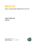
TransPort PT878
Initial Setup Decisions
Transducer
Clamp-On
Transducer
Y
Clamping
Fixture on
Pipe?
User Function
Fluid
N
Wetted
Transducer
Turn Tracking
Windows ON
Constant
Soundspeed
?
N
Y
Leave Tracking
Windows OFF
N
Perform
Special
Calc?
Y
Enter
User
Function
Corr. Factors
Special
Transducer
N
Engraved
Transducer #
?
Y
Enter
Fluid Type &
Soundspeed
Standard
Transducer
Diametric
Flow Path
?
Y
Enable
Reynolds
Correction
Y
Calibrate
Meter
?
Path
Complete
Remaining
Prompts
Pipe
Enter
Material &
Dimensions
Lining
N
Complete
Remaining
Prompts
Clamp-On
Transducer
?
Clamp-On
Transducer
?
N
Y
Complete
Remaining
Prompts
N
Energy
Velocity
Profile Bias
Linear?
N
Y
Multi-Point
Calibration
Table
N
Y
Enter
Material &
Thickness
Enable
Energy Option
Measure
Energy Usage
?
Y
Disable
Energy Option
Single-Point
Calibration
Factor
Complete
Remaining
Prompts
916-091A
N
[OVER]
DONE
June 2003
TransPort PT878
Guidelines for New Users
Follow these guidelines for the initial setup of your PT878:
Transducer Tab:
• The simplest way to determine your transducer type is to
check the pipe for a clamping fixture. If your transducers
are mounted on the outside of the pipe with a clamping
fixture, you have clamp-on transducers. If your transducers
are inserted through the pipe wall via nozzles, you have
wetted transducers.
• If your transducers have a 2- or 3-digit transducer number
engraved on the body, you have standard transducers. If
there are no engraved numbers, you have special
transducers and must use the factory data sheet to set up
the transducers.
Pipe Tab:
• Complete the prompts in this menu.
Note: If you have wetted transducers and your pipe has a
lining, be sure to account for the lining thickness when
entering the pipe wall thickness.
Lining Tab:
• Complete the prompts in this menu only if you have clampon transducers and your pipe has a lining.
Fluid Tab:
• If your process involves a single fluid with minimal
pressure and temperature fluctuations, leave tracking
windows OFF and follow the prompts for your fluid.
• If you process multiple fluids or there are large pressure or
temperature fluctuations, turn tracking windows ON and
follow the prompts for your fluid.
916-091A
Path Tab:
• Follow the prompts for your transducer type.
Energy Tab:
• If you wish to measure only the flow rate through your
pipeline, skip this menu.
• If you wish to measure the energy transferred in a closedloop heating or cooling system, be sure the PT878 has
analog inputs for supply and return temperatures available.
Then, complete the prompts in this menu.
User Function Tab:
• If you wish to add a custom calculation to the standard ones
already available in the PT878, complete this menu.
Correction Factors Tab:
• The Reynolds Correction factor corrects the raw fluid
velocity measurement for the shape of a non-linear flow
profile. It should be enabled whenever the ultrasonic beam
is directed across the diameter of the pipe. This includes all
clamp-on and most wetted installations.
• The single-point Calibration Factor is used to calibrate the
PT878 by compensating for any small site parameter
inaccuracies. The factor is determined by calibration
against a known flow reference, and it is applied linearly to
all velocity calculations performed by the meter.
• The multi-point Calibration Table is rarely needed. It is
used when the single-point correction does not adequately
correct the raw velocity measurements across the full range
of flow rates.
See your User’s Manual for a more thorough discussion.
[OVER]
June 2003